Makita HR4040C Manual

SPECIFICATIONS
Voltage(V)
No load speed Blows per minute
Bit-type
Drilling capacities
Net weight
Cord length
Tungsten-carbitde
tipped bit
Current(A) Cycle(Hz) Continuous Rating(W) Max.Output(W)
Input Output
STANDARD EQUIPMENT
OPTIONAL ACCESSORIES
FEATURES AND BENEFITS
Revolutions per minute
The standard equipment for the tools shown may differ from country to country.
Bull Point 300, 450, Cold Chisel 300, 450, Clay Spade, Rammer, Grooving chisel, Bushing tool
Scaling Chisel 50 x 300, Chemical anchor adapter, Taper shank adapter,
Core Bit adapter, Grease Vessel(Hammer grease)
Models No.
Description
CONCEPTION AND MAIN APPLICATIONS
Product
TECHNICAL INFORMATION
5m(16.4ft)
6.6Kg
Core bit
HR4040C
Model HR4040C accepts spline shank bit and overcomes
competitors' models.
Its brief benefits are;
*Less operator's fatigue than competitors.
*Less vibration and reaction toward hands
*Better feeling at drilling and hammering
*Quick change of hammer bits with one touch sliding chuck system.
40mm Rotary Hammer (Spline drive bit type)
230 450 rpm.
Spline
40 mm (1-9/16")
105 mm (4-1/8")
1,250 2,500 bpm
Depth Gauge--------------------------------1pc.
Grease Vessel(Bit Grease)----------------1pc.
Plastic Carrying Case ---------------------1pc.
Side Grip (Cylindric form) ---------------1pc.
Tungsten-carbide tipped bit
Bit diameter : 12.7mm(1/2"), 16mm(5/8"), 18mm(11/16"), 19mm(3/4"), 20mm(13/16"), 22mm(7/8"),
25.5mm(1"), 28mm(1-1/8"), 30mm(1-3/16"), 32mm(1-1/4"), 35mm(1-3/8"), 38mm(1-1/2"),
40mm(1-9/16")
1. Double insulated
2. See the sheets attached for more information.
120
220
230
240
9.6
5.0
4.8
4.6
50/60
50/60
50/60
50/60
1050
1050
1050
1050
330
330
330
330
850
850
850
850
Bit-type : Spline shank
A
B
A: 19.2mm (3/4")
B: 16.6mm (5/8")
Side Grip (D - form) ---------------1pc.
470mm(18-1/2")
253mm(10")
100mm(3-15/16")
38mm
(1-1/2")

FEATURES AND BENEFITS
Spline shank hammer bit can be accepted.
Hammer bits for HR3520B, HR3850B and HR5000
can be used also with this HR4040C.
In case of employing as a demolition hammer,
the BOSCH type shank bit of 3/4" hex / 21/32"round can be
used also with HR4040C.
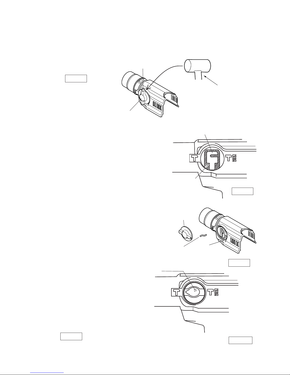
Simple slide locking chuck
Simple slide lock for securing inserted bit
Chisels can be locked at 12 positions through 360
°
.
By turning change ring while pushing it forward, the angle of chisel can be adjusted without taking
out inserted chisels.
Full resin covered body to protect the user from the electric shock.
The followings are the same features and benefits as those of HR4000C, HR5001C etc.
Simple slide lock for securing inserted tools
Its color tells how your machine is.
Green: On with no problem
Red : Approx. 8 hours before carbon brushes wear out
Off : Possibly trouble in switch or power supply cord
New dust sealing front cap prevents particles of dust from coming in
through the front of machine.
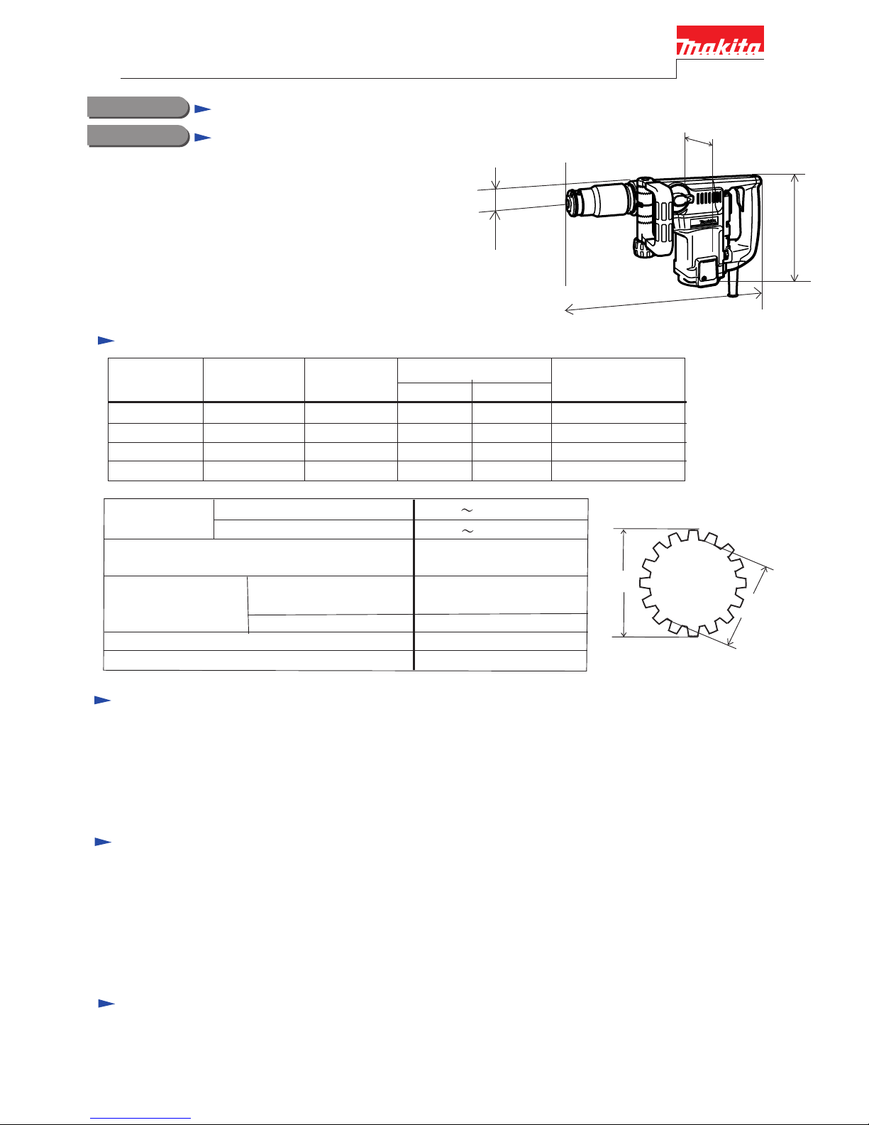
Electronic Speed Control Dial Optimum hammering speed can be selected in accordance with materials or tools.
Setting at low speed, ideal for such a light chipping works as scraping tiles,
removing bricks joint.
New Torque Limiting System Thanks to the Ball Clutch, stable torque control is assured even after long term use.
Large Rear Handle
Convenient Indicator Lamp
Auto Shut-off Carbon Brushes
Simple Slide Locking Chuck
Further Improvement in Dust proof Structure
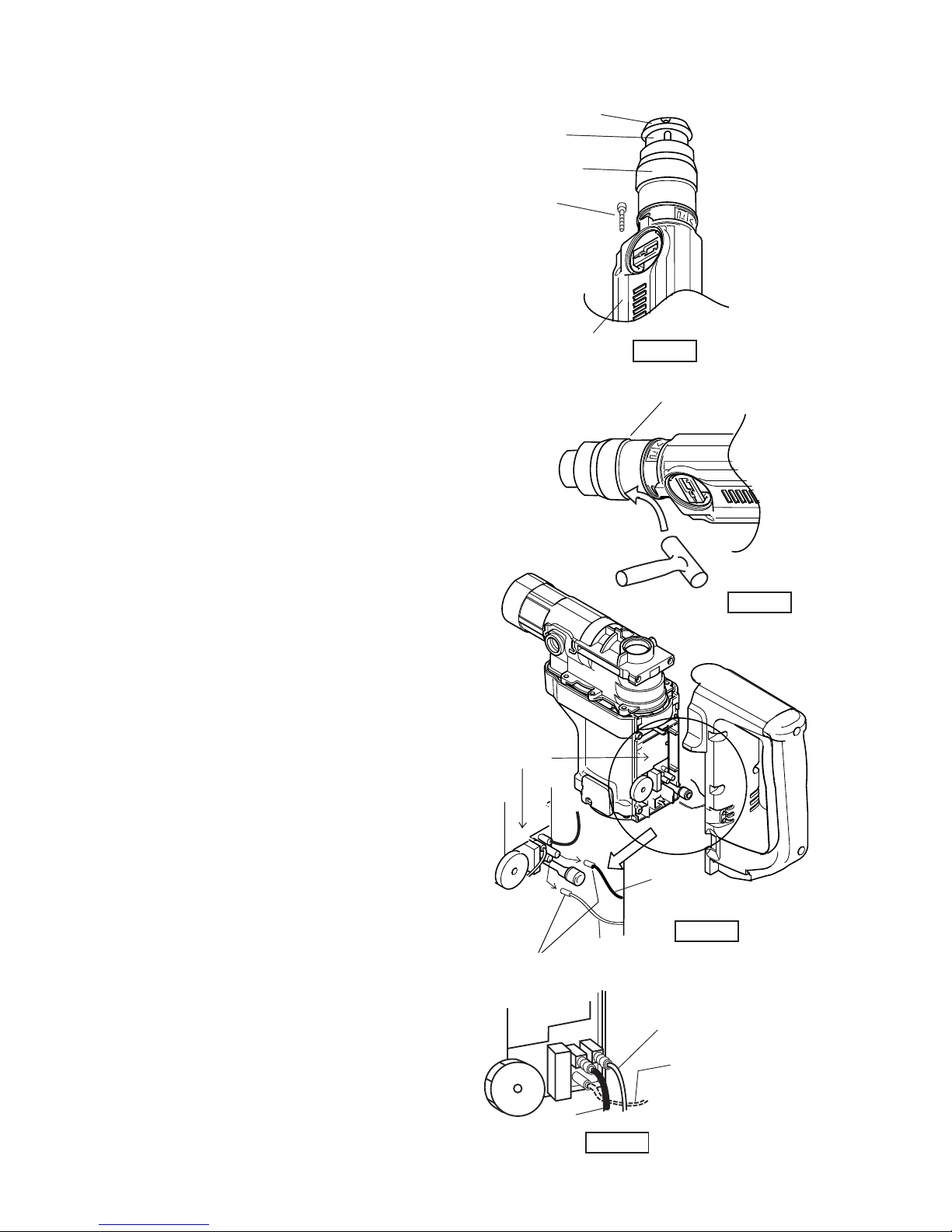
Replaceable without removing rear cover of machine.
(HILTI's model requires removal of rear cover.)
Easy Replacement of Power Supply Cord
Body Wholly Covered with Resin No electric shock to operator, even if bit accidentally hits against laid electric cables.
Barrel is also covered with resin, and so, it is possible to do chipping operations while
holding barrel with your hand.
Easy-to-Operate Large Trigger Fatigue-free in fingers even in a long continuous operation.
Can be gripped with both hands - convenient in downward chipping operations.
Big Action Mode Change Lever For easy shift of action mode
Thick Commutator The effective thickness of is segments has been enlarged.
Zig-Zag Varnish on Armature Coil For effective radiation from coil while protecting coil from dusts

COMPARISON CHART
Manufacturer
Model No.
Shank of bit
Continuous rating Input (W)
No load speed (rpm)
Blows per min.(bpm)
Blows power (J) Calculated by
MAKITA
Catalogue
Capacity TCT. bit
Core bit
Changeable working mode from
Hammering&Rotating to
Hammering only mutually
Chuck system
Changeable setting angle of bit
Electronic control
Indication lamp for
carbon brush change
Warning light for broken cord
and switch
Overall length (mm)
Weight (Kg)
MAKITA MAKITA Competitor A Competitor B
Model B
Model A
HR4040C HR4000C
Spline SDS-Max Spline Spline
1,050 1,050 1,000
950
Amperage under 120 V 9.6 A 9.6 A 8.8 A 9.4 A
230 - 450 180 - 360 120 - 320
1,250 - 2,500 1,600 - 3,200 1,100 - 2,850
230 - 450
1,250 - 2,500
6.7 J (4.9ft.lbs.)
6.7 J (4.9ft.lbs.)
6.7 J (4.9ft.lbs.)
6.7 J (4.9ft.lbs.)
5.1 J (3.8ft.lbs.) 6.3 J (4.6ft.lbs.)
5.7 J (4.2ft.lbs.)
__
Yes Yes Yes Yes
40mm(1-1/2")
105mm(4-1/8")
40mm(1-1/2")
105mm(4-1/8")
40mm(1-1/2") 40mm(1-1/2")
90mm(3-1/2") 90mm(3-1/2")
Slide locking
in one action
Turn locking in
two actions
Slide locking
in one action
Turn locking in
two actions
Yes.12 x 30
°
Yes.12 x 30
°
No No
Yes Yes Yes Yes
Yes Yes Yes Yes
Yes Yes Yes Yes
470 (18-1/2") 455 (17-7/8") 455 (17-7/8")
448 (17-5/8")
measured by MAKITA
Catalogue
6.6 (14.6 lbs)
6.6 (14.6 lbs)
6.4 (14.1 lbs) 6.4 (14.1 lbs)6.2 (13.7 lbs)
6.2 (13.7 lbs) 6.5 (14.3 lbs) 6.7 (14.8 lbs)
Standard
equipment
Steel carrying case
Cylindric form side grip
D-form side grip
Bit grease
Plastic caring case
Stopper pole

COMPARISON CHART
(1) Chipping
(3) Vibration and Noise
Model No. HR4040C 11233EVS
Vibration (m/s2)
Noise (dB)
5.2
Numbers in chart below are relative values when setting MAKITA
HR4040C 's data as 100.
Chipped amount
HR4040C HR4000C Model A
100
80
60
40
20
0
120 Operation without extension cord.
Operation with extension cord.
100 100 95 95
110
110
HR4040C HR4000C
100
80
40
20
120 100 100 100 100
8585
(2) Drilling (Diameter of hammer bit for this test : 28mm)
HR4000C
106
5.9
106
7.2
107
Model A

(2) Installing Change Lever Complete
(1) Removing Change Lever Complete
Set Change Lever Complete at neutral position,
and slightly hit the back side of lock button with a plastic hammer to remove it.
(See Fig.1.)
2. Install change lever on crank housing
with setting crank pin 4 into the upper hole of
change link.
( The change lever has to be set at hammering position.)
Figure 1
1. Change link is constructed to be slidden up and down.
Slide the change link upward with your finger.
(See Fig.2)
plastic hammer
Lock button
Change lever
at neutral position.
Figure 2
(See Fig 3A)
Remark Do not operate the machine without change lever.
Otherwise it causes damage of the inner mechanism.
Change link
slided upward
with finger
Upper hole of change link
Crank pin 4 has to be
set into the upper hole
of change link
Change lever
Figure 3
Position of
Crank pin 4
( The change lever has to be set at hammering position.)
Figure 3A

(3) Replacement of armature
1. Remove tool holder by sliding down
sleeve 46.
And then the sleeve 46 can be removed
from the machine. (see Fig. 4)
Remove chuck cover by hitting its edge
with plastic hammer slightly. (see Fig.5)
2. Remove compression spring 50 after
removing retaining ring S-50.
And then remove crank housing cover
after taking off pan head screw. (see Fig. 4)
3. Remove handle. (see Fig.6)
< Note >
The upper 2 screws are different
from other 4 screws.
Be careful in assembling / disassembling.
The upper 2 screws : Pan Head Screw M5x20
The other 4 screws : Tapping Screw 5x20
4. Separate terminal (black and white) below
from the controller. (see Fig. 6)
5. Remove pick up coil after taking off
fix rod. (see Fig.8 at the next page)
< Note >
Pull lead wire not so strong. Otherwise it
causes the breakage of lead wire.
6. Remove controller after separating 3 terminals
(black, white and red) from controller. (see Fig. 7)
Fig. 4
Chuck cover
Sleeve 46
Tool holder cap
Crank housing
cover complete
Pan Hd. Screw for
fastening crank
housing cover
complete
Fig. 5
Plastic hammer
Edge of chuck cover
Controller
Terminal
Black
White
Fig. 6
Controller White
Black
Red
Fig. 7

7. Remove rear cover by loosening
tapping screw 4x18.
And then loosen Hex Nut M6
with holding fan with your hand.
(see Fig.8)
8. Remove crank housing.
(see Fig. 8)
9. Remove armature together with
gear housing from motor housing
by hitting the armature shaft after
removing fan. (see Fig.8)
10.Assembling armature
Install ball bearing 6000 and
oil seal 12 on gear housing by
pressing them.
(see Fig. 9)
(4) Removing Chuck section
1. Remove tool holder cap by sliding down
sleeve 46.
And then the sleeve 46 can be removed
from the machine. (see Fig. 4)
Remove cuck cover by hitting its edge
with plastic hammer slightly. (see Fig.5)
2. Remove compression spring 50 after
removing retaining ring S-50.
And then remove crank housing cover
after taking off pan head screw. (see Fig. 4)
3. Remove ring spring 29. (see Fig.10)
< Note >
The ring spring 29 can be removed easily
with repairing tool No.1R-212.
Tapping screw 4x18
Fan
Rear cover
Hex Nut M6
Fix rod
Motor housing
Crank housing
Controller
Pick up coil
Gear housing complete
Ball bearing 6000
Oil seal 12
Gear housing complete
Armature
Baffle plate
< Note >
Apply the grease to
the part marked with
on oile seal 12.
Fig. 8
Fig. 9
Ring spring 29
Repairing tool No.1R-212.
Fig. 10

4. Remove leaf spring 39 and pin 8 (see Fig.11)
5. Remove roller 12 from tool holder
with sliding down chuck ring. (see Fig.11)
(5) Assembling Chuck section
1. Assemble the spare parts on tool holder in the order illustrated as per Fig.11.
< Remark >
The concave of leaf spring 39 has to come to that
of the chuck ring, when they are assembled. (see Fig.12)
Tool holder
Ring spring 29
Leaf spring 39
Roller 12
Chuck ring
Compression spring 50
Retaining ring S-50
4
5
6
7
2
1
Pin 8
3
Concave of chuck ring Concave of leaf spring 39
Fig.12
Fig. 11

2. When assembling chuck ring, chuck cover and sleeve 46, the following concaves and convexes have to meet
each other. (see Fig.13)
< Remark >
Install a hammer bit on the machine, and slide the sleeve 46
toward the tool holder cap.
3 outer concaves of chuck ring
3 inner convexes of chuck cover
3 concaves of sleeve 46 (However, the concave with triangle mark is not included in these 3 ones.)
3. When installing tool holder cap on the above sleeve 46, the following convex and concave have to meet each other.
The concave with triangle mark inside of sleeve 46
The convex of the tool holder cap
4.
5. Make sure whether the installed hammer bit can be locked firmly, or not.
6. Make sure whether the installed hammer bit can be removed from the machine by sliding down the chuck cover.
(6) Removing the tool holder section
1. Seal case can be removed with a slotted screwdriver easily.
(see Fig.14)
2. Pull out tool holder after removing retaining ring R56.
(see Fig.15)
Triangle mark on
the concave of
Sleeve 46
Convex of Tool holder cap
3 inner convexes
of Chuck cover
3 outer concaves
of Chuck ring
3 concaves of Sleeve 46
Fig. 13
Tool holder
Seal case
Retaining ring R56
Tool holder
Fig. 14 Fig. 15

(7) Removing the cylinder 28.5
Cylinder 28.5 is installed in crank housing by pressing slightly.
So, it can be removed easily by striking the crank housing vertically
on the table in several time. ( see Fig. 16)
(8) Assembling piston, rod and crank shaft
1. Assemble 2 pcs. of O ring 30 on cylinder 28.5 and insert
the cylinder 28.5 into the crank housing. (see Fig.17)
2. Push the piston into the cylinder 28.5
till the hole of rod can be seen through
the hole of crank housing. (see Fig. 18)
3. Assemble crank shaft on crank housing
with fitting the pole of crank shaft in the hole
of rod. (see Fig. 18)
(9) Assembling fluoride ring 25 on impact bolt
1. After installing fluoride ring 20 on impact bolt,
the ring comes stretched and its edge come protruding
from the groove. (see Fig. 19)
2. In order to correct the deformation, insert impact bolt
with the fluoride ring 20 into the repairing tool, Taper
sleeve (No.1R259) and leave it in the repairing
tool about 10 seconds. (see Fig. 19)
3. When inserting impact bolt into tool holder, be careful
not to put the ring out of the grooove of impact bolt.
Fig. 16
O ring 30
Cylinder 28.5 Crank housing
O ring 30
O ring 22
Cylinder liner 28.5
Piston
Hole of rod
Crank room
Crank housing
Crank shaft
flat washer 42
Fig. 17
Fig. 18
Fig. 19
grooves on
Impact Bolt
Fluoride Ring 25
O ring 20
Before Correction :
Rings' edges are protruding from grooves
on Impact Bolt.
Taper Sleeve
Correction
After Correction :
Rings' edges are placed under grooves
on Impact Bolt.
Impact Bolt
corrected

(10) Assembling tool holder section
1. Assemble the the spare parts of Fig.20 into
the crank housing.
< Note >
Straight bevel gear 33 can be installed into
the crank housing by pushing it with tool
holder smoothly. (see Fig.20)
2. Press urethane ring 35 and flat washer 35
on tool holder. And press ball bearing 6907
into bearing holder .
And then tool holder on which urethane
ring 35 and flat washer 35 are installed,
is pressed into the above bearing holder
and ball bearing 6907. (see Fig.21)
3. When pressing tool holder into straight
bevel gear 33, the cams on tool holder and the same
of straight bevel gear 33 have to engage each other.
(see Fig. 23)
* Adjust 12 concaves of straight bevel gear 33
to 6 concaves of crank housing by turning
straight bevel gear 33. (see Fig.22)
* Adjust the cams of lock sleeve A to the
same of tool holder. (see Fig.23)
* Press tool holder into crank housing after
the following process.
- Face the flat part of lock sleeve A to the
hole for change lever setting.
- Engage 6 convexes of lock sleeve B with
6 concaves of crank housing.
(see Fig.22 and 23)
Washer 16
Rubber ring 19
Sleeve 16
Slide sleeve 16
Ring 33
Compression spring 33
Striker with
O ring 22
Straight
bevel gear 33 Crank housing
Fig.20
Tool holder
Ball bearing 6907
Bearing holder
Urethane ring 35
Flat washer 35
Tool holder
Fig.21
Fig.22
6 concaves of
crank housing
12 concaves (cam section)
of straight bevel gear 33
Hole for installing
of change lever
The cams sections have
to be engaged each other
Tool holder Lock sleeve A
The flat section of lock
sleeve A have to face to
the hole for change lever
The convexes have to be
engaged with the 6 concaves
of crank housing.
Fig.23
Lock sleeve B

(11) Assembling torque limiter section
1. Assemble ball bearing 1207, flat washer 12
(24mm in outer diameter) and torque limiter
complete to straight bevel gear 10. (see Fig.24)
< Note >
Be careful not to lose pin 4 for lock of
circular nut M25-35.
2. Assemble 2 change keys into the groove
on the shaft of straight bevel gear 10.
Set flat washer 12 (24mm in outer diameter)
and retaining ring S12 on the above assembled
change keys.
And then assemble flat washer 12 (28mm in
outer diameter) adjusting it in the concaves
of change keys. (see Fig.24)
3. Assemble retaining ring S12 into the groove
on the shaft of straight bevel gear 10 sliding
down 2 change keys. And make sure, whether
the retaining ring S12 is assembled in the groove
firmly. (see Fig.24 and 25)
< Note >
Be careful not to expand the retaining ring 12
too wide.
4. Assemble slide plate, compression spring 3
and guide pin 2 on change link. (see Fig.26)
5. Assemble flat washer 12 (28mm in outer
diameter) into the groove of change link
and install the assembled torque limiter
section in the ball bearing 608 which is
installed in the gear housing. (see Fig.26)
Concave of
change key
Change key
Flat washer 12
(28mm in diameter)
Retaining ring S12
Flat washer 12
(24mm in diameter)
Concave for
retaining ring
Ball bearing 1207
Straight bevel gear 10
Fig. 24
Pin 4
Circular nut M25-35
Fig. 25
Slide plate
Compression
spring 3
Guide pin 2
Change link
Flat washer 12
(28mm in diameter)
Groove of
change link

(12) Lubrication
Apply Makita grease No.00 to the following parts in order to prevent unusual abrasion and overheating
of machine.
1. O Ring on striker
2. Inner face of ring 33
3. Inner face of slide sleeve
4.Outer face of straight bevel gear 33
and its gear section
5.O Ring on piston and inner face of rod's hole
6.Outer face of impact bolt, and tool holder side and crank housing side of rubber ring 19
7.Where the stem of straight bevel gear 10 is contact with torque limiter complete
8.Lips of oil seal 12 and 35
9.Needle bearing in gear housing
10.All of gear section
(13) Fastening torque of screws
Crank cap on crank housing : 6 - 10 N.m
(4.3 - 7.2 ft.lbs)
Needle bearing
Flat washer 16
Rubber ring 19
Sleeve 16
Slide sleeve 16
Ring 33
Striker
Straight bevel gear 33
Crank housing

Circuit Diagram
3
4
5
2
Switch
Power supply
cord
Controller
Brush holder
Brush holder
Support
complete
Black
White
Violet
Black
White
Orange
Orange
Violet
Red
Other manuals for HR4040C
3
Table of contents
Other Makita Rotary Hammer manuals

Makita
Makita DHR164 User manual

Makita
Makita HR005GZ01 User manual

Makita
Makita DHR400 User manual

Makita
Makita HR2450 Series User manual

Makita
Makita HR006G User manual

Makita
Makita HPR2410 Operating and maintenance manual

Makita
Makita HR4500C User manual

Makita
Makita HR1821 User manual

Makita
Makita HR1830 User manual

Makita
Makita HR4001C User manual

Makita
Makita DHR171 User manual

Makita
Makita HR4500C User manual

Makita
Makita HR2800 User manual

Makita
Makita XRH06 User manual

Makita
Makita BHR240 Manual

Makita
Makita HR4000C User manual

Makita
Makita HR3200C User manual

Makita
Makita HR4003C User manual

Makita
Makita HR140D User manual

Makita
Makita HR4041C Quick start guide