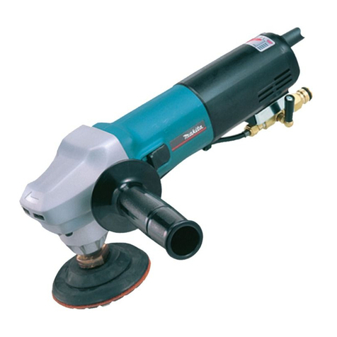
Makita 9217SPC User manual

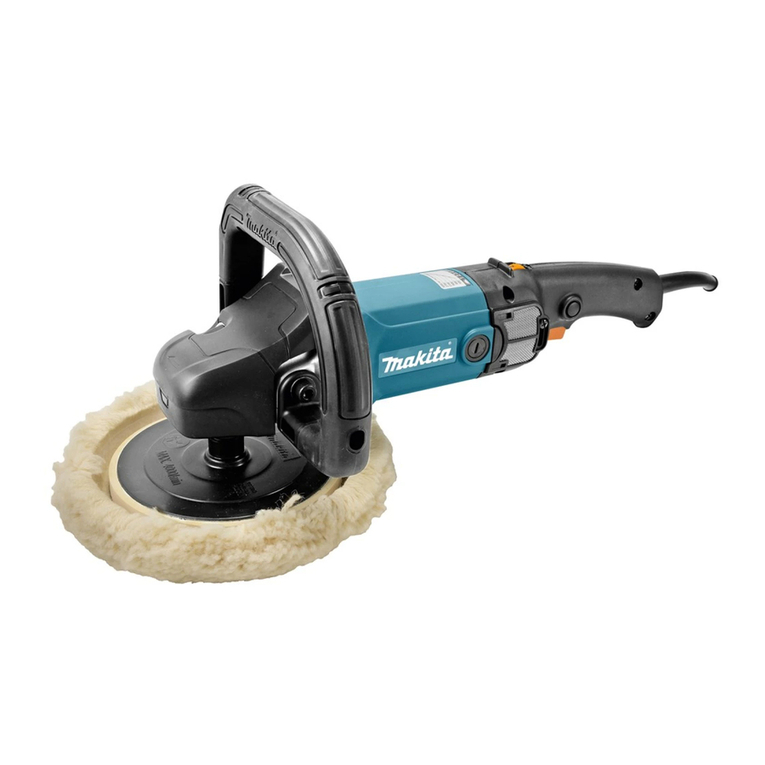
Electronic Sander Polisher
Overall
length
No load speed
(RPM)
180
mm
(7")
MODEL
9217SPC
Net weight Spindle thread
INSTRUCTION MANUAL
1,500
-
2,800
DOUBLE
INSULATION
470
mm
(1
8-
112")
3.5
kg
(7.7
Ibs)
5/8-11
UNC

IMPORTANT
SAFETY INSTRUCTIONS
(For
All
Tools)
WARNING: WHENUSINGELECTRICTOOLS, BASICSAFETY
PRECAUTIONSSHOULDALWAYS BE FOLLOWEDTO REDUCE
THE RISK OF FIRE, ELECTRIC SHOCK, AND PERSONAL
INJURY, INCLUDING THE FOLLOWING:
READ ALL INSTRUCTIONS.
1.
KEEP WORK AREA CLEAN. Cluttered areas and benches invite injuries.
2.
CONSIDER WORK AREA ENVIRONMENT. Don't use power tools
in
damp
or wet locations. Keep work area well
lit.
Don't expose power tools to rain.
Don't use tool
in
presence of flammable liquids or gases.
3.
KEEP CHILDREN AWAY. All visitors should be kept away from work area.
Don't let visitors contact tool or extension cord.
4.
STORE IDLETOOLS. When not
in
use, toolsshouldbestored
in
dry, andhigh
or locked-up place
-
out of reach of children.
5.
DON'T FORCETOOL.
It
willdothejob betterand safer at the ratefor which
it
was intended.
6.
USE RIGHT TOOL. Don't force small tool or attachment to do thejob of a
heavy-dutytool. Don't usetoolfor purpose notintended; for example, don't
use circular saw for cutting tree limbs or logs.
7.
DRESS PROPERLY. Don't wear looseclothingor jewelry. They canbecaught
in
moving parts. Rubber gloves and non-skid footwear are recommended
when working outdoors. Wear protectivehair covering tocontainlonghair.
8.
USESAFETY GLASSES. Also use face or dust mask ifcutting operation is
dusty.
9.
DON'T ABUSE CORD. Nevercarry tool by cordor yank
it
todisconnectfrom
receptacle. Keep cord from heat, oil, and sharp edges.
IO.
SECURE WORK. Use clamps or a vise to hold work. It's safer than using
your hand and
it
frees both hands to operate tool.
11.
DON'T OVERREACH. Keep proper footing and balance at all times.
12.
MAINTAINTOOLS WITH CARE. Keep tools sharp and clean for better and
safer performance.Follow instructionsfor lubricatingand changingacces-
sories. Inspecttoolcordsperiodicallyandifdamaged, haverepairedbyautho-
rized service facility. Inspect extension cords periodically and replace if
damaged. Keep handles dry, clean, and free from oil and grease.
13.
DISCONNECTTOOLS. When not
in
use, beforeservicing, andwhen chang-
ing accessories, such as blades, bits, cutters.
L
Ampere Rating
More Not More
Than Than
0-
6
6
~
10
10
-
12
12
-
16
3
Total Length
of
Cord in Feet
0
-
25
26
-
50
51
-
100 101
-
150
AWG
18 16 16 14
18 16 14 12
16 16
14
12
14 12
Not Recommended

VOLTAGE WARNING: Beforeconnecting
the
tooltoa power source (receptacle,
outlet, etc.) be sure
the
voltage supplied is the same as that specified on the
nameplateof the tool. A power source withvoltage greater than that specified
for
the
toolcan result
in
SERIOUS INJURYto the user
-
as well as damage to
the
tool. If
in
doubt,
DO
NOT PLUG
IN
THE TOOL. Using a power source with
voltage less than the nameplate rating is harmful to the motor.
1.
2.
3.
4.
5.
6.
ADDITIONAL SAFETY RULES
Check the backing pad carefully for cracks, damage or deformity before
operation. Replace cracked, damaged
or
deformed pad immediately.
Hold the tool firmly.
Keep hands away from rotating parts.
Makesure abrasive disc
or
wool
bonnetisnotcontactingthe workpiecebefore
the switch is turned on.
Do
not leave the tool running. Operate the tool only when hand-held.
Do
nottouch
the
workpieceimmediatelyafter operation;
it
maybeextremely
hot and could burn your skin.
SAVE THESE INSTRUCTIONS.
4

HOW
TO
USE
Installing side grip (auxiliary handle)
Screw the side grip on the tool securely.
The side grip can be installed on either
side
of
the tool, whichever
is
convenient.
Switch action
To
start the tool, simply pull the trigger.
Release
the trigger to stop. For continuous
operation without having to keep your
finger on the trigger, just pull the trigger
and then push in the lock button with
your thumb.
To
stop the tool from the
lock position, simply pull the trigger again
and release
it.
Speed changes
If
the knob on the switch lever in front
is
turned to the "H" setting, the high speed
is
obtained; if
set
to the
"L"
setting, the low
speed results. Use the suitable speed setting
in order to obtain the best performance
and finish.
High speed
......
For disc sanding
Low speed
......
For polishing
I
Fig.
Switch
trigger
\'
\
Lock button
Fig.
:
Fig.
2
5

Knobsetting interms
of
speed
The tool speed can be
set
for anywhere from 1,500 to
2,800
rpm. Simply align any knob
numbered setting with the arrow indicator. Consult chart below for approximate speeds
obtained for each of the numbered settings.
You can also obtain speeds other than the settings by adjusting the knob in between.
For example, for 2,150 rpm, align
so
that arrow will be pointed halfway between the
numbers
3
and
4.
Numbered Setting
CAUTION
:
The knob for speed settings can be turned
only
as
far
as
6
and back to 1. Do notforce
the knob past
6
or the speed change func-
tion may no longer work.
RPM
2
I
1750
2800
CAUTION
:
MOVING A SANDING DISC
OR
WOOL BONNET.
ALWAYS SWITCH OFF AND UNPLUG THE TOOL BEFORE INSTALLING
OR
RE-
CAUTIONS
:
1.
Always wear safety
glasses
and mask duringoperation.
2.
Gripthe tool firmly with bothhands.
3.
Do not touch the rotatingabrasive disc.
4.
When sanding metal surfaces, be careful of the flying sparks. Handle tool in terms of
the direction they fly.
6

FOR
USE
AS
A
SANDER
For disc sanding, assemble tool
as
seen
at
right.
Hold
the spindle firmly with the wrench.
Put on the rubber pad and
all,
then tighten
lock nut usingthe lock nut wrench, turning
clockwise.
Make certain the rubber pad tightening nut
is
not loose.
Abrasive
disc
I
I
Fig.
L
L
Loosen
1
Lock
nut
wrench
Fig.
5
Operation
When applying sander to work surface,
keep the angle
at
10
to
15
degrees and use
gentle pressureonly.
Fig.
6
7

FOR
USE
AS A
POLISHER
For polishing operation, assemble the tool
.
as
at
right. Hold the spindle firmly with
the wrench
17.
Put on the rubber pad, then
tighten lock nut using the lock nutwrench
provided, turning clockwise. Next, put
wool bonnet on, fastening
it
securely with
strings
as
snugly
as
possible, near the
center. Tuck in the loose ends of the cord
in betweenthe wool bonnet and the rubber
pad.
CAUTION
:
Loose
cord ends when using the wool
bonnet can be very dangerous. Always tuck
them safety in out of the way.
Lock
nut
wrench
.
Fig.
8
Fig.
9
Operat
ion
When polishing, keep the angle
at
about
15
degrees and work gently in the direction
the polisher
is
turning.
Fig.
IO
8

MAINTENANCE
CAUTION
:
Always be sure that the tool
is
switched off and unpluggedbefore attempting to perform
inspection or maintenance.
Replacing
carbon
brushes
I
Remove and check the carbon brushes
regularly. Replacewhen they wear down to
the limit mark. Keep the carbon brushes
clean and free to slip in the holders. Both
carbon brushes should
be
replaced
at
the
same time. Use only Makita carbon brushes.
Limit
mark
Fig.
11
Use
a
screwdriver to remove the brush
holder caps. Take out the worn carbon
brushes, insert the new ones and secure
the brush holder caps.
Brush holder
cap
I
Fig.
1:
To maintain product SAFETY and RELIABILITY, repairs, any other maintenance or
adjustment should be performed by Makita Authorized or Factory Service Centers,
always using Makita replacement parts.
9

ACCESSORIES
CAUTIO
N
:
These accessories or attachments are recommended for use with your Makitatool specified inthis
manual. The use of any other accessories or attachments might present a risk of injuryto persons.
The accessories or attachments should be used
only
in the proper and intended manner.
Wool
bonnet
180
(Part
No.
743404-0)
Lock
nut
wrench
28
(Part
No.
78241 3-41
Abrasive disc Wrench
17
(Part
No.
781008-0)
Grit
I
Part
NO.
I
Discs per pkg
742067-9
742068-7
24 742069-5
10
Rubber pad
170
(Part
No.
743012-7)
100
I
742090-4
120
I
742091-2
Lock
nut
48
(Part
No.
224517-11
10

June-06-'94
US
180
mm
(7")
Model
9217SPC
ELECTRONIC SANDER-POLISHER
Note: The switch and other part configurations
may differ from country to country.
11

MODEL
9217SPC June-06-’94
US
/LM
$FD
DESCRIPTION
‘k:M
$&,
DESCRIPTION
27
28
29
30
32
33
34
35
36
38
39
40
41
42
44
45
46
47
49
50
52
53
00
MACHINE
~
1
1
1
2
1
1
2
2
2
1
1
1
1
1
1
1
1
2
2
1
2
1
1
1
2
3
4
5
6
7
8
9
10
11
12
13
15
16
19
20
21
22
23
24
25
26
1
2
1
1
1
1
1
1
1
2
1
1
1
4
1
1
1
1
1
1
1
1
4
-
FIELD ASSEMBLY
Pan
Head
Screw
M5x70 IWith Washer
&
Bond)
Baffle
Plate
Ball Bearing 608LB
Insulation
Washer
ARMATURE ASSEMBLY
IWith
Item
4
-
71
Fan
68
Tool
Rest
Pan
Head
Screw
M5
Ball
Rearing
6002LLB
Retaining
Ring
S
-
15
Bearing
Retainer
19-33
Pan
Head
Screw
M5x40 (With Washer)
Needle
Bearing 810
Retaining
Ring
5-12
Swal
Bevel
Gear
44
Rearmg Retainer
22-34
Ball
Bearing
6201LLB
Bearing Box
Dust
Seal
20
Pan
Head
Screw
M4x14 (With Washerl
ea^
nouSlng
cover
GW
tiouslng
Note: The
switch
and
other part specifications may
differ from
country to country.
Spindle
Woodruff
Key
3
Lock Nut
Pan
Head
Screw
M4x45 (With Washerl
Label
Name
Plate
Rivet
0-5
Carbon
Brush
Brush
Holder
Cap
Controller
Rubber
Pin
4
0
Ring
17
Knob
28
Motor Housing
Cord
Cord
Guard
Strain
Relief
Pan
Head Screw
M4x18 IWithWasherl
Pan
Head
Screw
M4x6 (With Washerl
Switch
Pan
Head
Screw
M4x28 (With Washer)
Handle Cover
Grip
37
MAKlTA
LlMmED
ONE
YEARWARRANTY
Warranty
Policy
Every Makita tool is thoroughly inspected and tested before leaving the factory. It is warranted to
be
free of defects from workmanship and materials for the period of ONE YEAR from the date of
original purchase. Should any trouble develop duringthis one-year period. return the COMPLETE
1001,
freight prepaid, to
one
of Makita’s Factory
or
Authorized Service Centers. If inspection shows
the trouble is caused by defective workmanship
or
material, Makita
will
repair
(or
at
our
option,
replace) without charge.
ThisWarranty does not apply where:
repairs have
been
made
or
attemptedby others:
.
repiurs are required because of
normal
wear and tear
.
The tool has
been
abused, misused
or
improperly maintained,
.
alterations have
been
made to
the
tool.
IN NO EVENT SHALL MAKlTA BE LIABLE
FOR
ANY INDIRECT, INCIDENTAL
OR
CON-
SEQUENTIAL DAMAGES FROM THE SALE
OR
USE
OF
THE PRODUCT. THIS DISCLAIMER
APPLIES BOTH DURING AND AFTER THE TERM
OF
THISWARRANTY.
MAKlTA DISCLAIMS LIABILITY
FOR
ANY IMPLIED WARRANTIES, INCLUDING IMPLIED
WARRANTIES OF “MERCHANTABILITY”
AND
“FITNESS FOR A SPECIFIC PURWSE,”
AFTER THEONE-YEAR TERM
OF
THISWARRANTY.
This Warranty
gives
you specific
legal
rights, and you may
also
have otherrights which
vary
from
state to state. Some States do not
allow
the exclusion
or
limitationof incidental
or
consequential
damages,
so
the above limitation
or
exclusion may
not
apply to You. Some states do not allow
limitation
on
how
long
an
implied warranty lasts,
so
the
above limitation may not apply to you.
Makita Corporation
3-11
-8,
Sumiyoshi-cho,
Anjo, Aichi
446
Japan
883892-062
PRINTED
IN
JAPAN
1994
-
7
-
N
Other manuals for 9217SPC
1
Table of contents
Other Makita Sander manuals

Makita
Makita BO4553 User manual

Makita
Makita 9227CB User manual

Makita
Makita 9046 User manual

Makita
Makita M9200 User manual

Makita
Makita 9741 User manual

Makita
Makita GV5010 User manual

Makita
Makita PW5001C User manual

Makita
Makita SA7000C User manual

Makita
Makita 9032 User manual

Makita
Makita 9207SPC User manual
Popular Sander manuals by other brands

Westfalia
Westfalia 802410 instruction manual

Milwaukee
Milwaukee 6080-20 Operator's manual

Parkside
Parkside PMFS 200 C3 Translation of the original instructions

Dynabrade
Dynabrade 58050 Important operating, maintenance and safety instructions

Sealey
Sealey SA802 instructions

Sealey
Sealey SA720.V2 instructions