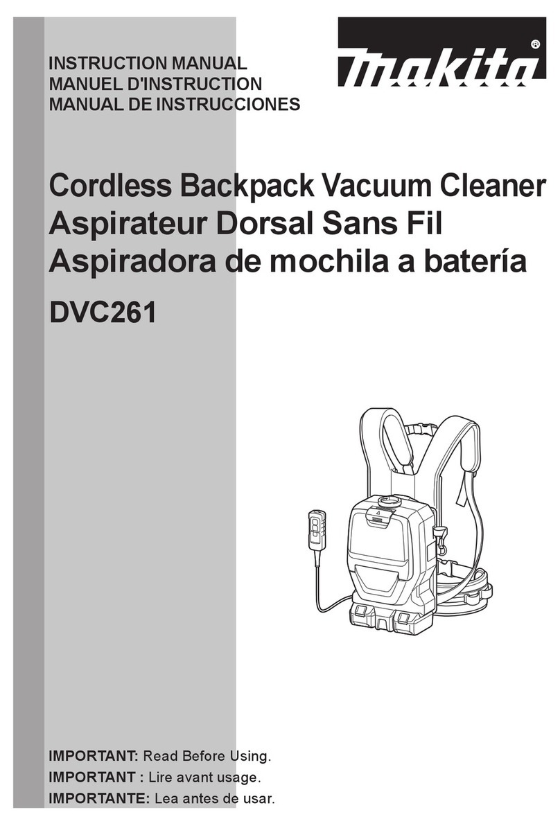
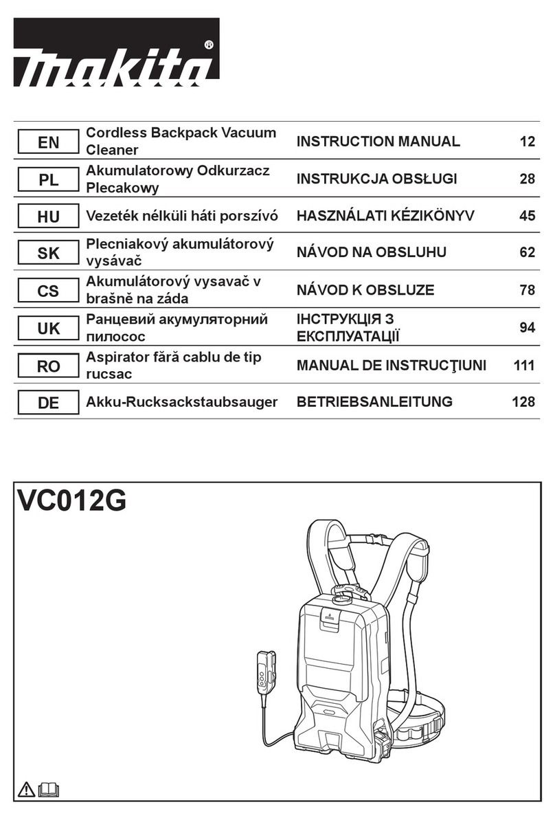
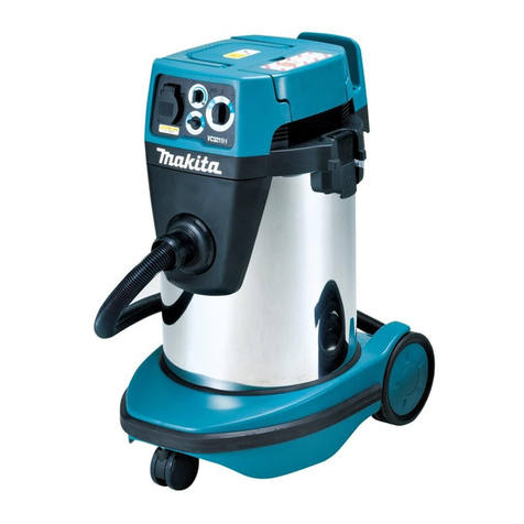
Makita DVC265 User manual

DVC265
EN Cordless Backpack Vacuum
Cleaner INSTRUCTION MANUAL 9
FR Aspirateur dorsal sans l MANUEL D’ INSTRUCTIONS 21
DE Akku-Rucksackstaubsauger BETRIEBSANLEITUNG 34
IT Aspirapolvere spalleggiato a
batteria ISTRUZIONI PER L’ USO 47
NL Ruggedragen accustofzuiger GEBRUIKSAANW IJZING 61
ES Aspiradora de mochila a
batería MANUAL DE
INSTRUCCIONES 74
PT Aspirador Costal a Bateria MANUAL DE INSTRUÇÕ ES 8 7
DA Akku rygstøvsuger BRUGSANVISNING 100
EL Φορητή μηχανή
αναρρόφησης πλάτης ΕΕΙΙΔΙ ΔΗΙΝ 111
TR Akülü Sırt Süpürgesi KULLANMA KILAVUZU 125

1
2
3
Fig.1
1
2
Fig.2
12
2
1
Fig.3
12
Fig.4
2
1
Fig.5
1
2
Fig.6
1
Fig.7
2

1
Fig.8
Fig.9
1
2
3
Fig.10
1
2
Fig.11
1
2
3
Fig.12
2
1
Fig.13
1
2
Fig.14
1
2
3
Fig.15
3

1
234
Fig.16
2
1
34
Fig.17
1
Fig.18
123
Fig.19
1
Fig.20
Fig.21
4

1
2
Fig.22
1
2
Fig.23
2
1
3
Fig.24
3
2
1
4
1
Fig.25
Fig.26
Fig.27
Fig.28
5

1
Fig.29
1
Fig.30
Fig.31
1
Fig.32
21
3
4
Fig.33
2
3
1
Fig.34
1
Fig.35
6

2
1
1
2
Fig.36
Fig.37
1
Fig.38
2
1
Fig.39
1
Fig.40
2
1
1
2
Fig.41
7

3
1
2
Fig.42
2
1
Fig.43
Fig.44
1
2
3 4
Fig.45
Fig.46
8

9ENGLISH
ENGLISH (Original instructions)
SPECIFICATIONS
Model: DVC265
C apac ity F ilter bag 2.0 L
D ust bag 1 .5 L
Max imum air v olume 1 .8 m3/ min
Vac uum 1 1 0 h P a
D imensions ( L x W x H )
( ex c lud ing th e h arness) 230 mm x 1 5 2 mm x 373 mm
R ated v oltage D .C . 36 V
Net w eigh t 3.9 - 4 .5 kg
Due to our continuing program of research and development, the specications herein are subject to change
w ith out notic e.
Specications may differ from country to country.
• T h e w eigh t d oes not inc lud e ac c essories but battery c artrid ge( s) . T h e ligh test and h eav iest c ombination w eigh t
of th e applianc e and battery c artrid ge( s) are sh ow n in th e table.
Applicable battery cartridge and charger
Battery c artrid ge BL 1 8 1 5 N / BL 1 8 20 / BL 1 8 20B / BL 1 8 30 / BL 1 8 30B / BL 1 8 4 0 /
BL 1 8 4 0B / BL 1 8 5 0 / BL 1 8 5 0B / BL 1 8 6 0B
C h arger D C 1 8 R C / D C 1 8 R D / D C 1 8 R E / D C 1 8 S D / D C 1 8 S E / D C 1 8 S F
• S ome of th e battery c artrid ges and c h argers listed abov e may not be av ailable d epend ing on y our region of
resid enc e.
WARNING: Only use the battery cartridges and chargers listed above. U se of any oth er battery c artrid ges
and chargers may cause injury and/or re.
Symbols
T h e f ollow ing sh ow th e sy mbols used f or th e eq uip-
ment. Be sure th at y ou und erstand th eir meaning bef ore
use.
R ead instruc tion manual.
T ake partic ular c are and attention.
Ni-MH
Li-ion O nly f or EU c ountries
D o not d ispose of elec tric eq uipment or
battery pac k togeth er w ith h ouseh old
w aste material! I n observ anc e of th e
European D irec tiv es, on W aste Elec tric
and Elec tronic Eq uipment and Batteries
and A c c umulators and W aste Batteries and
A c c umulators and th eir implementation
in ac c ord anc e w ith national law s, elec tric
eq uipment and batteries and battery
pac k( s) th at h av e reac h ed th e end of
th eir lif e must be c ollec ted separately and
returned to an env ironmentally c ompatible
rec y c ling f ac ility .
Intended use
T h e tool is intend ed f or c ollec ting d ry d ust. T h e tool
is suitable f or c ommerc ial use, f or ex ample in h otels,
schools, hospitals, factories, shops, ofces and rental
businesses.
Noise
T h e ty pic al A -w eigh ted noise lev el d etermined ac c ord -
ing to EN6 0335 -2-6 9 , EN6 0704 -2-1 :
S ound pressure lev el ( L pA ) : 70 d B( A ) or less
U nc ertainty ( K) : 2.5 d B( A )
T h e noise lev el und er w orking may ex c eed 8 0 d B ( A ) .
WARNING: W ear ear protection.
Vibration
T h e v ibration total v alue ( tri-ax ial v ec tor sum) d eter-
mined ac c ord ing to EN6 0335 -2-6 9 :
W ork mod e: operation w ith out load
Vibration emission ( ah) : 2.5 m/ s2or less
U nc ertainty ( K) : 1 .5 m/ s2
NOTE: T h e d ec lared v ibration emission v alue h as
been measured in ac c ord anc e w ith th e stand ard test
meth od and may be used f or c omparing one tool w ith
anoth er.
NOTE: T h e d ec lared v ibration emission v alue
may also be used in a preliminary assessment of
ex posure.

10 ENGLISH
WARNING: T h e v ibration emission d uring ac tual
use of th e pow er tool c an d if f er f rom th e d ec lared
emission v alue d epend ing on th e w ay s in w h ic h th e
tool is used .
WARNING: Be sure to id entif y saf ety measures
to protec t th e operator th at are based on an estima-
tion of ex posure in th e ac tual c ond itions of use ( taking
ac c ount of all parts of th e operating c y c le suc h as
th e times w h en th e tool is sw itc h ed of f and w h en it is
running id le in ad d ition to th e trigger time) .
EC Declaration of Conformity
For European countries only
T h e EC d ec laration of c onf ormity is inc lud ed asA nnex A
to th is instruc tion manual.
SAFETY W ARNINGS
Cordless vacuum cleaner safety
warnings
WARNING: IMPORTANT! READ CAREFULLY
all safety warnings and all instructions BEFORE
USE . F ailure to f ollow th e w arnings and instruc tions
may result in electric shock, re and/or serious injury.
1 . Before use, make sure that this cleaner must
be used by people who have been adequately
instructed on the use of this cleaner.
2. Do not use the cleaner without the lter.
Replace a damaged lter immediately.
3. Do not attempt to pick up ammable materials,
re works, lighted cigarettes, hot ashes, hot
metal chips, sharp materials such as razors,
needles, broken glass or the like.
4 . NEVER USE THE CLEANER IN THE VICINITY
OF GASOLINE, GAS, PAINT,ADHESIVES OR
OTHER HIGHLY EX PLOSIVE SUBSTANCES.
T h e sw itc h emits sparks w h en turned O N and
O F F .A nd so d oes th e motor c ommutator d uring
operation.A d angerous ex plosion may result.
5 .
Never vacuum up toxic, carcinogenic, com-
bustible or other hazardous materials such as
asbestos, arsenic, barium, beryllium, lead, pes-
ticides, or other health endangering materials.
6 . Never use the cleaner outdoors in the rain.
7. Do not use close to heat sources (stoves, etc.).
8 . Do not block cooling vents. These vents per-
mit cooling of the motor. Blockage should be
carefully avoided otherwise the motor will burn
out from lack of ventilation.
9 . Keep proper footing and balance at all times.
1 0. Do not fold, tug or step on the hose.
1 1 . Stop the cleaner immediately if you notice
poor performance or anything abnormal
during operation.
1 2. DISCONNECT THE BATTERIES. W hen not in
use, before servicing, and when changing
accessories.
1 3. Clean and service the cleaner immediately
after each use to keep it in tiptop operating
condition.
14. MAINTAIN THE CLEANER W ITH CARE. Keep
the cleaner clean for better and safer per-
formance. Follow instructions for changing
accessories. Keep handles dry, clean, and free
from oil and grease.
15. CHECK DAMAGED PARTS. Before further use
of the cleaner, a guard or other part that is
damaged should be carefully checked to deter-
mine that it will operate properly and perform
its intended function. Check for alignment of
moving parts, binding of moving parts, break-
age of parts, mounting, and any other condi-
tions that may affect its operation. A guard or
other part that is damaged should be properly
repaired or replaced by an authorized service
center unless otherwise indicated elsewhere
in this instruction manual. Have defective
switches replaced by authorized service cen-
ter. Don’ t use the cleaner if switch does not
turn it on and off.
16. REPLACEMENT PARTS. W hen servicing, use
only identical replacement parts.
1 7. STORE IDLE CLEANER. W hen not in use, the
cleaner should be stored indoors.
18. Be kind to your cleaner. Rough handling can
cause breakage of even the most sturdily built
cleaner.
19. Do not attempt to clean the exterior or interior
with benzine, thinner or cleaning chemicals.
Cracks and discoloration may be caused.
20. Do not use cleaner in an enclosed space where
ammable, explosive or toxic vapors are given
off by oil-base paint, paint-thinner, gasoline,
some mothproong substances, etc., or in
areas where ammable dust is present.
21 . Do not operate the cleaner while under the
inuence of drugs or alcohol.
22. As a basic rule of safety, use safety goggles or
safety glasses with side shields.
23. Use a dust mask in dusty work conditions.
24 . This machine is not intended for use by per-
sons including children with reduced physical,
sensory or mental capabilities, or lack of expe-
rience and knowledge.
25 . Children should be supervised to ensure that
they do not play with the cleaner.
26 . Never handle batteries and cleaner with wet
hands.
27. Use extreme caution when cleaning on stairs.
28 . Do not use the cleaner as a stool or work
bench. The machine may fall down and may
result in personal injury.
Battery tool use and care
1 . Recharge only with the charger specied by
the manufacturer. A c h arger th at is suitable f or
one type of battery pack may create a risk of re
w h en used w ith anoth er battery pac k.
2. Use power tools only with specically desig-
nated battery packs. U se of any oth er battery
packs may create a risk of injury and re.
11 ENGLISH
3. W hen battery pack is not in use, keep it away
from other metal objects, like paper clips,
coins, keys, nails, screws or other small metal
objects, that can make a connection from one
terminal to another. S h orting th e battery termi-
nals together may cause burns or a re.

4 . Under abusive conditions, liquid may be
ejected from the battery; avoid contact. If con-
tact accidentally occurs, ush with water. If
liquid contacts eyes, additionally seek medical
help. Liquid ejected from the battery may cause
irritation or burns.
5 . Do not use a battery pack or tool that is dam-
aged or modied. Damaged or modied batteries
may ex h ibit unpred ic table beh av iour resulting in
re, explosion or risk of injury.
6 . Do not expose a battery pack or tool to re or
excessive temperature. Exposure to re or tem-
perature abov e 1 30 ° C may c ause ex plosion.
7. Follow all charging instructions and do not
charge the battery pack or tool outside the
temperature range specied in the instruc-
tions. C h arging improperly or at temperatures
outside the specied range may damage the
battery and increase the risk of re.
Service
1 . Have your power tool serviced by a ualied
repair person using only identical replacement
parts. T h is w ill ensure th at th e saf ety of th e pow er
tool is maintained .
2. Follow instruction for lubricating and chang-
ing accessories.
3. Keep handles dry, clean and free from oil and
grease.
Important safety instructions for
battery cartridge
1 .
Before using battery cartridge, read all instruc-
tions and cautionary markings on (1) battery
charger, (2) battery, and (3) product using battery.
2. Do not disassemble battery cartridge.
3. If operating time has become excessively
shorter, stop operating immediately. It may
result in a risk of overheating, possible burns
and even an explosion.
4 . If electrolyte gets into your eyes, rinse them
out with clear water and seek medical atten-
tion right away. It may result in loss of your
eyesight.
5 . Do not short the battery cartridge:
( 1 ) Do not touch the terminals with any con-
ductive material.
( 2) Avoid storing battery cartridge in a con-
tainer with other metal objects such as
nails, coins, etc.
( 3) Do not expose battery cartridge to water
or rain.
A battery short can cause a large current
ow, overheating, possible burns and even a
breakdown.
6 . Do not store the tool and battery cartridge in
locations where the temperature may reach or
exceed 50 ° C (122 ° F).
7. Do not incinerate the battery cartridge even if
it is severely damaged or is completely worn
out. The battery cartridge can explode in a re.
8 . Be careful not to drop or strike battery.
9 . Do not use a damaged battery.
1 0.
The contained lithium-ion batteries are subject to
the Dangerous Goods Legislation requirements.
F or c ommerc ial transports e.g. by th ird parties,
f orw ard ing agents, spec ial req uirement on pac k-
aging and labeling must be observ ed .
F or preparation of th e item being sh ipped , c onsult-
ing an ex pert f or h az ard ous material is req uired .
P lease also observ e possibly more d etailed
national regulations.
T ape or mask of f open c ontac ts and pac k up th e
battery in suc h a manner th at it c annot mov e
around in th e pac kaging.
1 1 . Follow your local regulations relating to dis-
posal of battery.
1 2. Use the batteries only with the products
specied by Makita. I nstalling th e batteries to
non-compliant products may result in a re, exces-
siv e h eat, ex plosion, or leak of elec troly te.
SAVE THESE INSTRUCTIONS.
CAUTION: Only use genuine Makita batteries.
U se of non-genuine Makita batteries, or batteries th at
h av e been altered , may result in th e battery bursting
causing res, personal injury and damage. It will
also v oid th e Makita w arranty f or th e Makita tool and
c h arger.
Tips for maintaining maximum
battery life
1 . Charge the battery cartridge before completely
discharged. Always stop tool operation and
charge the battery cartridge when you notice
less tool power.
2. Never recharge a fully charged battery car-
tridge. Overcharging shortens the battery
service life.
3.
Charge the battery cartridge with room tempera-
ture at 10 ° C - 40 ° C (50 ° F - 104 ° F). Let a hot
battery cartridge cool down before charging it.
4 . Charge the battery cartridge if you do not use
it for a long period (more than six months).
Important safety instructions for
wireless unit
1 . Do not disassemble or tamper with the wire-
less unit.
2. Keep the wireless unit away from young chil-
dren. If accidentally swallowed, seek medical
attention immediately.
3. Use the wireless unit only with Makita tools.
4 . Do not expose the wireless unit to rain or wet
conditions.
5 . Do not use the wireless unit in places where
the temperature exceeds 50° C (122° F).
6 . Do not operate the wireless unit in places
where medical instruments, such as heart
pace makers are near by.

12 ENGLISH
7. Do not operate the wireless unit in places
where automated devices are near by. I f oper-
ated , automated d ev ic es may d ev elop malf unc tion
or error.
8 . Do not operate the wireless unit in places
under high temperature or places where
static electricity or electrical noise could be
generated.
9 . The wireless unit can produce electromagnetic
elds (EMF) but they are not harmful to the
user.
1 0. The wireless unit is an accurate instrument. Be
careful not to drop or strike the wireless unit.
1 1 . Avoid touching the terminal of the wireless
unit with bare hands or metallic materials.
1 2. Always remove the battery on the product
when installing the wireless unit into it.
1 3. W hen opening the lid of the slot, avoid the
place where dust and water may come into the
slot. Always keep the inlet of the slot clean.
14. Always insert the wireless unit in the correct
direction.
15. Do not press the wireless activation button
on the wireless unit too hard and/or press the
button with an object with a sharp edge.
16. Always close the lid of the slot when
operating.
1 7. Do not remove the wireless unit from the slot
while the power is being supplied to the tool.
D oing so may c ause a malf unc tion of th e w ireless
unit.
18. Do not remove the sticker on the wireless unit.
19. Do not put any sticker on the wireless unit.
20. Do not leave the wireless unit in a place where
static electricity or electrical noise could be
generated.
21 . Do not leave the wireless unit in a place sub-
ject to high heat, such as a car sitting in the
sun.
22. Do not leave the wireless unit in a dusty or
powdery place or in a place corrosive gas
could be generated.
23. Sudden change of the temperature may bedew
the wireless unit. Do not use the wireless unit
until the dew is completely dried.
24 . W hen cleaning the wireless unit, gently wipe
with a dry soft cloth. Do not use benzine, thin-
ner, conductive grease or the like.
25 . W hen storing the wireless unit, keep it in the
supplied case or a static-free container.
26 . Do not insert any devices other than Makita
wireless unit into the slot on the tool.
27. Do not use the tool with the lid of the slot dam-
aged. W ater, d ust, and d irt c ome into th e slot may
c ause malf unc tion.
28 . Do not pull and/or twist the lid of the slot more
than necessary. R estore th e lid if it c omes of f
f rom th e tool.
29 . Replace the lid of the slot if it is lost or
damaged.
SAVE THESE INSTRUCTIONS.
FUNCTIONAL
DESCRIPTION
CAUTION: Always be sure that the tool is
switched off and the battery cartridge is removed
before adjusting or checking function on the tool.
Installing or removing battery
cartridge
CAUTION: Always switch off the tool before
installing or removing of the battery cartridge.
CAUTION: Hold the tool and the battery car-
tridge rmly when installing or removing battery
cartridge. F ailure to h old th e tool and th e battery
cartridge rmly may cause them to slip off your hands
and result in d amage to th e tool and battery c artrid ge
and a personal injury.
Fig.1: 1. R ed ind ic ator 2. Button 3. Battery c artrid ge
T o remov e th e battery c artrid ge, slid e it f rom th e tool
w h ile slid ing th e button on th e f ront of th e c artrid ge.
T o install th e battery c artrid ge, align th e tongue on th e
battery c artrid ge w ith th e groov e in th e h ousing and slip
it into plac e. I nsert it all th e w ay until it loc ks in plac e
w ith a little c lic k. I f y ou c an see th e red ind ic ator on th e
upper sid e of th e button, it is not loc ked c ompletely .
CAUTION: Always install the battery cartridge
fully until the red indicator cannot be seen. I f not,
it may accidentally fall out of the tool, causing injury to
y ou or someone around y ou.
CAUTION: Do not install the battery cartridge
forcibly. I f th e c artrid ge d oes not slid e in easily , it is
not being inserted c orrec tly .
Tool / battery protection system
T h e tool is eq uipped w ith a tool/ battery protec tion sy s-
tem. T h is sy stem automatic ally c uts of f pow er to th e
motor to ex tend tool and battery lif e. T h e tool w ill auto-
matic ally stop d uring operation if th e tool or battery is
plac ed und er one of th e f ollow ing c ond itions.
Overload protection
W h en th e tool is operated in a manner th at c auses it to
d raw an abnormally h igh c urrent, th e tool automatic ally
stops w ith out any ind ic ation. I n th is situation, turn th e
tool of f and stop th e applic ation th at c aused th e tool to
bec ome ov erload ed . T h en turn th e tool on to restart.
Overheat protection
W h en th e tool is ov erh eated , th e tool stops automatic ally .
L et th e tool c ool d ow n bef ore turning th e tool on again.
Overdischarge protection
W h en th e battery c apac ity bec omes low , th e tool stops
automatic ally . I f th e prod uc t d oes not operate ev en
w h en th e sw itc h es are operated , remov e th e batteries
f rom th e tool and c h arge th e batteries.

13 ENGLISH
Indicating the remaining battery
capacity
Only for battery cartridges with the indicator
Fig.2: 1. I nd ic ator lamps 2. C h ec k button
P ress th e c h ec k button on th e battery c artrid ge to ind i-
c ate th e remaining battery c apac ity . T h e ind ic ator lamps
ligh t up f or a f ew sec ond s.
Indicator lamps Remaining
capacity
Lighted Off Blinking
75 % to 1 00%
5 0% to 75 %
25 % to 5 0%
0% to 25 %
C h arge th e
battery .
T h e battery
may h av e
malf unc tioned .
NOTE: D epend ing on th e c ond itions of use and th e
ambient temperature, th e ind ic ation may d if f er sligh tly
f rom th e ac tual c apac ity .
Switch box position
T h e sw itc h box c an be h ooked on eith er sid e of th e
low er belt. A rrange th e c ord so th at th e sw itc h box
c omes to y our d esired sid e. T o prev ent th e c ord f rom
being d amaged , pass th e c ord th rough th e h ook as
illustrated .
Fig.3: 1. H ook 2. C ord
Adjusting belts
T h e tigh tness of th e sh ould er belts, upper and low er
belts can be adjusted. Put your arms through the shoul-
der belts rst then fasten the lower and upper belts.
T o tigh ten, pull th e end of th e strap as illustrated . T o
loosen, pull up th e end of th e f astener.
Lower belt
Fig.4: 1. S trap 2. F astener
Shoulder belts
Fig.5: 1. S trap 2. F astener
Upper belt
Fig.6: 1. S trap 2. F astener
Carrying hook
A lw ay s grab th e c arry ing h ook w h en h and ling th e v ac -
uum c leaner bod y .
Fig.7: 1. C arry ing h ook
Stand-by switch
T h e stand -by sw itc h is th e sw itc h to turn on/ of f th e
w ireless ac tiv ation f unc tion. T h e v ac uum c leaner is in
th e stand -by state regard less of th e sw itc h position and
it runs w h en button is push ed .
Fig.8 : 1. S tand -by sw itc h
Switch position Status
A U T O I
( O N) T h e v ac uum c leaner is in th e stand -by
state and th e w ireless ac tiv ation f unc tion
is av ailable.
O
( O F F ) T h e v ac uum c leaner is in th e stand -by
state h ow ev er th e w ireless ac tiv ation
f unc tion is not av ailable.
Switch action
T o start v ac uuming, press button onc e. T h e v ac uum
c leaner w ill start in th e same suc tion pow er w h en y ou
turned it of f prev iously . W h en y ou press button
w h ile th e v ac uum c leaner is running, th e suc tion pow er
sw itc h es betw een normal ( 1 ) and h igh er ( 2) suc tion
pow er.T o turn of f th e v ac uum c leaner, press button.
Fig.9
NOTE: I f y ou w ant to run th e v ac uum c leaner along
w ith th e sw itc h operation of th e tool c onnec ted to th e
v ac uum c leaner ( w ireless ac tiv ation f unc tion) , set th e
stand -by sw itc h to " I ( O N) " .
NOTE: To use the wireless activation function, nish
th e tool registration bef oreh and . R ef er to " W I R EL ES S
A C T I VA T I O N F U NC T I O N" sec tion f or d etail.
NOTE: W h en using th e w ireless ac tiv ation f unc -
tion, y ou w ill not be able to stop th e v ac uuming
by button.
Hose band
H ose band c an be used f or h old ing th e h ose or f ree
noz z le.
T o sec ure th e h ose to th e v ac uum c leaner bod y , pass
th e h ose band th rough th e slot on th e bod y . Y ou c an
attac h th e h ose band on eith er sid e.
Fig.10: 1. H ose band 2. S lot 3. H ose
ASSEMBLY
CAUTION: Always be sure that the tool is
switched off and the battery cartridge is removed
before carrying out any work on the tool.
Assembling hose
I nsert th e h ose c uf f into th e v ac uum c leaner bod y and
turn it c loc kw ise.
Fig.11: 1. H ose c uf f 2. Vac uum c leaner bod y

14 ENGLISH
Connecting the tool
I f th e bent pipe assembly is attac h ed to th e h ose,
loosen th e sleev e of bent pipe assembly and remov e it.
Fig.12: 1. H ose 2. Bent pipe assembly 3. S leev e
1. A ttac h th e f ront c uf f to th e h ose f or d ust ex trac tion.
W h en c onnec ting th e f ront c uf f , make sure th at it is
sec urely sc rew ed on th e h ose.
2. C onnec t th e f ront c uf f to th e tool's ex trac tion
outlet.
Fig.13: 1. F ront c uf f 2. Ex trac tion outlet 3. H ose
T h e f ront c uf f c an be d etac h ed by turning it c ounter-
c loc kw ise w h ile h old ing th e h ose.
NOTE: A lw ay s use a suitable f ront c uf f . W h en using
th e f ront c uf f 24 , attac h it to th e f ront c uf f 22 th at is
c onnec ted to th e h ose.
Fig.14: 1. F ront c uf f 22 2. F ront c uf f 24
Using as a cleaner
I f y ou w ant to use th is prod uc t as a c leaner, f ollow th e
below proc ed ures.
NOTICE: If the front cuff is attached to the hose,
remove it beforehand.
NOTE: T h e bent pipe assembly , ex tension w and , and
noz z les are supplied as optional ac c essories in some
c ountries.
NOTE: T h ere are tw o ty pes of bent pipe assembly ;
th e one f or slid e-ty pe ex tension w and and th e one f or
ring-ty pe ex tension w and . I f y ou prepare th e bent pipe
assembly , c h oose th e one f or y our d esired ex tension
w and ty pe.
1. F asten th e sleev e of bent pipe assembly onto th e
h ose.
Fig.15: 1. H ose 2. Bent pipe assembly 3. S leev e
T o remov e th e bent pipe assembly , loosen th e sleev e of
bent pipe assembly f rom th e h ose.
2. T w ist and insert th e noz z le to th e ex tension w and .
Fig.16: 1. Ex tension w and 2. F ree noz z le
3. T -sh ape noz z le 4. T -sh ape noz z le ( slim)
NOTE: By tw isting th e noz z le w h ile inserting, th e noz -
z le c an be attac h ed to th e ex tension w and sec urely .
3. F ollow th e proc ed ures below , d epend ing on th e
ty pe of th e ex tension w and :
NOTE: T h e slid e-ty pe ex tension w and and th e ring-
ty pe ex tension w and are not c ompatible w ith eac h
oth er. I f y ou w ant to c h ange th e slid e-ty pe ex tension
w and to th e ring-ty pe ex tension w and or v ic e v ersa,
c h ange th e bent pipe assembly also.
NOTE: T h e f ree noz z le c an be attac h ed to th e bent
pipe assembly d irec tly .
For the slide-type extension wand
S h ould er th e v ac uum c leaner bod y th en insert th e
ex tension w and into th e bent pipe assembly until it
c lic ks. T o d isc onnec t, ex trac t th e ex tension w and w ith
pressing th e button.
Fig.17: 1. Bent pipe assembly 2. Button 3. S lid e-
ty pe ex tension w and 4. F ree noz z le
The length of the wand can be adjusted.
With pressing the slide button, adjust the wand length.
T h e length is loc ked w h en release th e slid e button.
Fig.18 : 1. S lid e button
For the ring-type extension wand
S h ould er th e v ac uum c leaner bod y th en tw ist and insert
th e ex tension w and into th e bent pipe assembly . T o
d isc onnec t, tw ist and ex trac t it.
Fig.19: 1. Bent pipe assembly 2. R ing-ty pe ex ten-
sion w and 3. F ree noz z le
The length of the wand can be adjusted.
Loosen the ring on the wand and adjust the wand
length . T igh ten th e ring at y our d esired length .
Fig.20: 1. R ing
Hose hook
W h en y ou suspend th e operation, th e h ook on th e bent
pipe assembly c an be used f or h anging th e w and on th e
low er belt.
Fig.21
Installing lter bag / dust bag
Optional accessory
CAUTION: Do not use a damaged lter bag.
Always use the vacuum cleaner with the lter bag
properly installed. Otherwise the vacuumed dust
or particles may be exhausted from the cleaner
and they may cause respiratory disease to the
operator.
NOTICE: When the lter bag is already full, replace
w ith new one. W h en th e d ust bag is alread y f ull,
empty it. Continuous use with the lter bag/dust bag
f ull results in red uc ed suc tion pow er.
1. U nloc k th e latc h by lif ting th e bottom sid e. P ush
th e groov ed area to lif t th e f ront latc h ing sid e. P ull th e
latc h to open th e lid .
Fig.22: 1. H ook 2. L id
2. Insert the lter bag into the slit on the upper side of
th e room as illustrated .
Fig.23: 1. S lit 2. F ilter bag
W h en using th e d ust bag, insert th e brim of th e d ust bag
into th e slit.
Fig.24: 1. S lit 2. Brim 3. D ust bag
3. Align the hole of the lter bag with the hose cuff
and push th e c ard board portion to th e end . Make sure
that the rubber ring on the lter bag goes over the rim
on th e h ose c uf f .
Fig.25: 1. Rubber ring on the lter bag 2. R im on
th e h ose c uf f 3. C ard board portion of th e
lter bag 4. H ose c uf f

15 ENGLISH
OPERATION
WARNING: Operators shall be adequately
instructed on the use of the vacuum cleaner.
WARNING: This vacuum cleaner is not suit-
able for picking up hazardous dust.
CAUTION: This cleaner is for dry use only.
CAUTION: This cleaner is for indoor use only.
CAUTION: Always insert the battery cartridge
all the way until it locks in place. I f y ou c an see th e
red ind ic ator on th e upper sid e of th e button, it is not
loc ked c ompletely . I nsert it f ully until th e red ind ic ator
c annot be seen. I f not, it may ac c id entally f all out of
the tool, causing injury to you or someone around
y ou.
CAUTION: During operation, be conscious
of the vacuum cleaner on your back. Y ou may
lose y our balanc e if th e v ac uum c leaner bod y bumps
against a w all or th e h ose is h ooked by an obstac les.
1. S h ould er th e v ac uum c leaner bod y and f as-
ten lower and upper belts. Adjust the tightness as
nec essary .
Fig.26
2. P ress button to start v ac uuming. T o c h ange
th e suc tion pow er, press button w h ile th e v ac uum
c leaner is running. T h e suc tion pow er sw itc h es betw een
normal ( 1 ) and h igh er ( 2) suc tion pow er. P ress but-
ton to stop.
Fig.27
D uring th e operation, h ook th e sw itc h box on th e low er
belt or th e D -ring.
Fig.28
3. Replace the lter bag when it becomes full. Open
the lid and take out the lter bag. Pull the strip on the
side of the opening to shut the lter bag and dispose of
the lter bag in whole.
Fig.29: 1. S trip
W h en using a d ust bag, take out th e d ust bag and d is-
pose of th e d ust by releasing th e latc h .
Fig.30: 1. L atc h
NOTICE: Periodically check the lter bag if it is
full. Continuous use with the lter bag full results in
red uc ed suc tion pow er.
NOTICE: Do not use an used lter bag. The lter
bag is designed for single use. Using lter bag repeat-
edly may cause clogging of the lter and results in
d amage to th e c leaner. I f y ou w ant to use th e bag
repeated ly , use a d ust bag.
W IRELESS ACTIVATION
FUNCTION
W hat you can do with the wireless
activation function
T h e w ireless ac tiv ation f unc tion enables c lean and
c omf ortable operation. By c onnec ting a supported tool
to th e c leaner, y ou c an run th e c leaner automatic ally
along w ith th e sw itc h operation of th e tool.
Fig.31
NOTICE: Be sure to refer to the instruction man-
ual of the tool when using the cleaner with wire-
less activation function.
NOTICE: Do not disassemble or tamper with the
wireless unit.
NOTICE: To prevent dust coming into the slot
of the wireless unit, always close the lid securely
during operation and storage.
NOTICE: Do not remove the wireless unit while
the power is being supplied. D oing so may c ause a
malf unc tion of th e w ireless unit.
NOTICE: Do not press the wireless activation
button too hard and/or press the button with an
object with a sharp edge.
NOTE: W ireless ac tiv ation need s Makita tools
eq uipped w ith th e w ireless unit.
NOTE: P rior to th e initial use of th e w ireless ac tiv a-
tion f unc tion w ith eac h tool, th e tool registration is
required. Once the registration is nished with the
tool, th e re-registration is not req uired unless it is
c anc elled .
NOTE: Bef ore registration, be sure th at th e w ireless
unit is properly inserted .
NOTE: O ne w ireless unit c an register up to 1 0 links
w ith oth er w ireless units. I f more th an 1 0 oth er w ire-
less units are registered to one w ireless unit, th e one
registered earliest w ill be c anc elled automatic ally .
NOTE: T h e position of th e w ireless ac tiv ation button
v aries d epend ing on th e tool.
NOTE: T h e c leaner also starts by pressing button
w h en th e stand -by sw itc h is set to " I ( O N) " .
H ow ev er th e button w ill not w ork w h en th e w ire-
less ac tiv ation f unc tion is used .

16 ENGLISH
Installing the wireless unit
CAUTION: Place the cleaner on a at and
stable surface when installing the wireless unit.
NOTICE:
Clean the dust and dirt on the cleaner
before installing the wireless unit. D ust or d irt may c ause
malf unc tion if it c omes into th e slot of th e w ireless unit.
NOTICE:
To prevent the malfunction caused by
static, touch a static discharging material, such as
a metallic part, before picking up the wireless unit.
NOTICE:
W hen installing the wireless unit, always
be sure that the wireless unit is inserted in the cor-
rect direction and the lid is completely closed.
1. Open the lid on the cleaner as shown in the gure.
Fig.32: 1. L id
2.
I nsert th e w ireless unit to th e slot and th en c lose th e lid .
When inserting the wireless unit, align the projections
w ith th e rec essed portions on th e slot.
Fig.33: 1. W ireless unit 2. Projection 3. L id
4. R ec essed portion
W h en remov ing th e w ireless unit, open th e lid slow ly .
T h e h ooks on th e bac k of th e lid w ill lif t th e w ireless unit
as y ou pull up th e lid .
Fig.34: 1. W ireless unit 2. H ook 3. L id
A f ter remov ing th e w ireless unit, keep it in th e supplied
c ase or a static -f ree c ontainer.
NOTICE: Always use the hooks on the back of
the lid when removing the wireless unit. I f th e
h ooks d o not c atc h th e w ireless unit, c lose th e lid
c ompletely and open it slow ly again.
Tool registration for the cleaner
NOTE: A Makita tool supporting th e w ireless ac tiv a-
tion f unc tion is req uired f or th e tool registration.
NOTE: F inish installing th e w ireless unit to th e tool
bef ore starting th e tool registration.
NOTE:
D uring th e tool registration, d o not pull th e sw itc h
trigger on th e tool or push th e c leaner's sw itc h f or v ac uuming.
NOTE: R ef er to th e instruc tion manual of th e tool, too.
I f y ou w ish to ac tiv ate th e c leaner along w ith th e sw itc h
operation of the tool, nish the tool registration beforehand.
1. I nstall th e w ireless units to th e c leaner and th e
tool, respec tiv ely .
2. I nstall th e batteries to th e c leaner and th e tool.
3. S et th e stand -by sw itc h on th e c leaner to " I ( O N) " .
Fig.35: 1. S tand -by sw itc h
4. P ress th e w ireless ac tiv ation button on th e c leaner
f or 3 sec ond s until th e w ireless ac tiv ation lamp blinks in
green.A nd th en press th e w ireless ac tiv ation button on
th e tool in th e same w ay .
Fig.36: 1. W ireless ac tiv ation button 2. W ireless
ac tiv ation lamp
I f th e c leaner and th e tool are linked suc c essf ully , th e
w ireless ac tiv ation lamps w ill ligh t up in green f or 2
sec ond s and start blinking in blue.
NOTE: The wireless activation lamps nish blinking
in green af ter 20 sec ond s elapsed . P ress th e w ireless
ac tiv ation button on th e tool w h ile th e w ireless ac ti-
v ation lamp on th e c leaner is blinking. I f th e w ireless
ac tiv ation lamp d oes not blink in green, push th e w ire-
less activation button briey and hold it down again.
NOTE: W h en perf orming tw o or more tool registration
for the cleaner, nish the tool registration one by one.
Starting the wireless activation
function
NOTE: F inish th e tool registration f or th e c leaner f or
w ireless ac tiv ation.
NOTE: A lw ay s plac e th e c leaner so th at y ou c an see
th e status of th e w ireless ac tiv ation lamp.
NOTE: R ef er to th e instruc tion manual of th e tool, too.
A f ter registering a tool to th e c leaner, th e c leaner w ill
automatic ally runs along w ith th e sw itc h operation of
th e tool.
1. I nstall th e w ireless units to th e c leaner and th e
tool, respec tiv ely .
2. I nstall th e batteries to th e c leaner and th e tool.
3. C onnec t th e h ose of th e c leaner w ith th e tool.
Fig.37
4. S et th e stand -by sw itc h on th e c leaner to " I ( O N) " .
T h e w ireless ac tiv ation lamp w ill blink in blue.
Fig.38 : 1. S tand -by sw itc h
5. P ush th e w ireless ac tiv ation button on th e tool
briey. The wireless activation lamp will blink in blue.
Fig.39: 1. W ireless ac tiv ation button 2. W ireless
ac tiv ation lamp
6. P ull th e sw itc h trigger of th e tool. C h ec k if th e
c leaner runs w h ile th e sw itc h trigger on th e tool is being
pulled .
CAUTION: Always check if the wireless acti-
vation function works before starting a work with
the tool.
T o stop th e w ireless ac tiv ation, push th e w ireless ac tiv a-
tion button on th e tool or set th e stand -by sw itc h on th e
c leaner to " O ( O F F ) " .
NOTE: T h e w ireless ac tiv ation lamp on th e tool w ill
stop blinking in blue w h en th ere is no operation f or
2 h ours. I n th is c ase, press th e w ireless ac tiv ation
buttons on th e tool again.
NOTE: T h e c leaner starts/ stops w ith a d elay . T h ere is
a time lag w h en th e c leaner d etec ts a sw itc h opera-
tion of th e tool.
NOTE: T h e transmission d istanc e of th e w ireless unit
may v ary d epend ing on th e loc ation and surround ing
c irc umstanc es.
NOTE: W h en tw o or more tools are registered to one
c leaner, th e c leaner may start running ev en if y ou
d on' t pull th e sw itc h trigger bec ause oth er user is
using th e w ireless ac tiv ation f unc tion.

17 ENGLISH
Cancelling tool registration for the
cleaner
P erf orm th e f ollow ing proc ed ure w h en c anc elling th e
tool registration f or th e c leaner.
1. I nstall th e w ireless units to th e c leaner and th e
tool, respec tiv ely .
2. I nstall th e batteries to th e c leaner and th e tool.
3. S et th e stand -by sw itc h on th e c leaner to " I ( O N) " .
Fig.40: 1. S tand -by sw itc h
4. P ress th e w ireless ac tiv ation button on th e c leaner
f or 6 sec ond s. T h e w ireless ac tiv ation lamp blinks in
green and th en bec ome red .A f ter th at, press th e w ire-
less ac tiv ation button on th e tool in th e same w ay .
Fig.41: 1. W ireless ac tiv ation button 2. W ireless
ac tiv ation lamp
I f th e c anc ellation is perf ormed suc c essf ully , th e w ire-
less ac tiv ation lamps w ill ligh t up in red f or 2 sec ond s
and start blinking in blue.
NOTE: The wireless activation lamps nish blinking in
red af ter 20 sec ond s elapsed . P ress th e w ireless ac ti-
v ation button on th e tool w h ile th e w ireless ac tiv ation
lamp on th e c leaner is blinking. I f th e w ireless ac ti-
v ation lamp d oes not blink in red , push th e w ireless
activation button briey and hold it down again.
Erasing all tool registrations
Y ou c an erase all tool registrations f rom th e c leaner as
f ollow s.
Fig.42: 1. S tand -by sw itc h 2. W ireless ac tiv ation
button 3. W ireless ac tiv ation lamp
1. I nstall th e w ireless unit to th e c leaner.
2. I nstall th e batteries to th e c leaner.
3. S et th e stand -by sw itc h to " I ( O N) " .
4. H old d ow n th e w ireless ac tiv ation button f or about
6 sec ond s until th e w ireless ac tiv ation lamp blinks in red
( about tw ic e per one sec ond ) .
5. W h en th e w ireless ac tiv ation lamp starts blinking
in red, release your nger from the wireless activation
button. T h ereaf ter, h old d ow n th e w ireless ac tiv ation
button again f or about 6 sec ond s.
6. W h en th e w ireless ac tiv ation lamp starts blinking
f ast ( about 5 times per one sec ond ) in red , release y our
nger from the wireless activation button. When the
w ireless ac tiv ation lamp ligh ts up in red and later ligh ts
of f , all tool registrations are erased .
NOTE: I f th e w ireless ac tiv ation lamp d oes not blink
in red, press the wireless activation button briey and
try again.
Description of the wireless activation lamp status
Fig.43: 1. W ireless ac tiv ation button 2. W ireless
ac tiv ation lamp
T h e w ireless ac tiv ation lamp sh ow s th e status of th e w ireless ac tiv ation f unc tion. R ef er to th e below table f or th e
meaning of th e lamp status.
Status W ireless activation lamp Description
Color
On
Blinking Duration
(approximate)
S tand by Blue C leaner: c on-
tinuing
T ool: 2 h ours
W aiting f or th e tool registration or th e w ireless ac tiv ation f unc tion
is av ailable.
T h e lamp on th e c leaner blinks w h en th e stand -by sw itc h is set in
" I ( O N) " .T h e lamp on th e tool blinks w h en th e w ireless ac tiv ation
button is push ed . T h e lamp on th e tool w ill automatic ally turn of f
w h en no operation is perf ormed f or 2 h ours.
W h en th e tool is
running. T h e w ireless ac tiv ation of th e c leaner is av ailable and th e tool is
running.
T ool
registration G reen 20 sec ond s R ead y f or th e tool registration. S earc h ing th e tool to be registered .
2 sec ond s The tool registration has been nished. The wireless activation
lamp w ill start blinking in blue.
C anc elling/
erasing
tool
registration
R ed
( slow : 2 times/ sec .) 20 sec ond s R ead y f or th e c anc ellation of th e tool registration. S earc h ing th e
tool to be c anc elled .
( f ast: 5 times/ sec .) W h en th e
w ireless ac ti-
v ation button is
pressed d ow n.
R ead y to erase all tool registrations.
2 sec ond s T h e tool registration h as been c anc elled / erased . T h e w ireless
ac tiv ation lamp w ill start blinking in blue.
O th ers R ed 3 sec ond s T h e pow er is supplied to th e w ireless unit and th e w ireless ac tiv a-
tion f unc tion is starting up.
O f f - - T h e stand -by sw itc h is not set to " I ( O N) " .

18 ENGLISH
Troubleshooting for wireless activation function
Before asking for repairs, conduct your own inspection rst. If you nd a problem that is not explained in the manual,
d o not attempt to d ismantle th e tool. I nstead , ask MakitaA uth oriz ed S erv ic e C enters, alw ay s using Makita replac e-
ment parts f or repairs.
State of abnormality Probable cause (malfunction) Remedy
T h e w ireless ac tiv ation lamp d oes
not ligh t/ blink. T h e w ireless unit is not installed into th e
c leaner and / or th e tool.
T h e w ireless unit is improperly installed
into th e c leaner and / or th e tool.
I nstall th e w ireless unit c orrec tly .
T h e terminal of th e w ireless unit and / or
th e slot is d irty . G ently w ipe of f d ust and d irt on th e terminal of th e
w ireless unit and c lean th e slot of th e c leaner and /
or th e tool.
T h e w ireless ac tiv ation button on th e
tool h av e not been push ed . P ush th e w ireless ac tiv ation button on th e tool
briey. Make sure that the wireless activation lamp
is blinking in blue.
T h e stand -by sw itc h on th e c leaner is
not set to " I ( O N) " . S et th e stand -by sw itc h on th e c leaner to " I ( O N) " .
No pow er supply S upply th e pow er to th e tool and th e c leaner.
Cannot nish tool registration / can-
c elling tool registration suc c essf ully . T h e w ireless unit is not installed into th e
c leaner and / or th e tool.
T h e w ireless unit is improperly installed
into th e c leaner and / or th e tool.
I nstall th e w ireless unit c orrec tly .
T h e terminal of th e w ireless unit and / or
th e slot is d irty . G ently w ipe of f d ust and d irt on th e terminal of th e
w ireless unit and c lean th e slot of th e c leaner and /
or th e tool.
T h e stand -by sw itc h on th e c leaner is
not set to " I ( O N) " . S et th e stand -by sw itc h on th e c leaner to " I ( O N) " .
No pow er supply S upply th e pow er to th e tool and th e c leaner.
I nc orrec t operation Push the wireless activation button briey and
perf orm th e tool registration/ c anc ellation proc ed ures
again.
T h e tool and c leaner are aw ay f rom
eac h oth er ( out of th e transmission
range) .
G et th e tool and th e c leaner c loser to eac h oth er.
T h e max imum transmission d istanc e is approx i-
mately 1 0 m h ow ev er it may v ary ac c ord ing to th e
c irc umstanc es.
Before nishing the tool registration/
c anc ellation;
- th e sw itc h trigger on th e tool is pulled
or;
- th e c leaner's sw itc h to start v ac uuming
is push ed .
Push the wireless activation button briey and
perf orm th e tool registration/ c anc ellation proc ed ures
again.
T h e tool registration proc ed ures f or
th e tool or th e c leaner h as not been
nished.
P erf orm th e tool registration proc ed ures f or th e tool
and th e c leaner at th e same timing.
R ad io d isturbanc e by oth er applianc es
w h ic h generate h igh -intensity rad io
w av es.
Keep th e tool and th e c leaner aw ay f rom th e appli-
anc es suc h as W i-F i d ev ic es and mic row av e ov ens.

19 ENGLISH
State of abnormality Probable cause (malfunction) Remedy
T h e c leaner d oes not run along w ith
th e sw itc h operation of th e tool. T h e w ireless unit is not installed into th e
c leaner and / or th e tool.
T h e w ireless unit is improperly installed
into th e c leaner and / or th e tool.
I nstall th e w ireless unit c orrec tly .
T h e terminal of th e w ireless unit and / or
th e slot is d irty . G ently w ipe of f d ust and d irt on th e terminal of th e
w ireless unit and c lean th e slot of th e c leaner and /
or th e tool.
T h e w ireless ac tiv ation button on th e
tool h av e not been push ed . P ush th e w ireless ac tiv ation button on th e tool
briey. Make sure that the wireless activation lamp
is blinking in blue.
T h e stand -by sw itc h on th e c leaner is
not set to " I ( O N) " . S et th e stand -by sw itc h on th e c leaner to " I ( O N) " .
More th an 1 0 tools are registered to
th e c leaner. P erf orm th e tool registration again.
I f more th an 1 0 tools are registered to th e c leaner,
th e tool registered earliest w ill be c anc elled
automatic ally .
T h e c leaner erased all tool
registrations. P erf orm th e tool registration again.
No pow er supply S upply th e pow er to th e tool and th e c leaner.
T h e tool and c leaner are aw ay f rom
eac h oth er ( out of th e transmission
range) .
G et th e tool and th e c leaner c loser to eac h oth er.
T h e max imum transmission d istanc e is approx i-
mately 1 0 m h ow ev er it may v ary ac c ord ing to th e
c irc umstanc es.
R ad io d isturbanc e by oth er applianc es
w h ic h generate h igh -intensity rad io
w av es.
Keep th e tool and th e c leaner aw ay f rom th e appli-
anc es suc h as W i-F i d ev ic es and mic row av e ov ens.
T h e c leaner runs w h ile th e tool' s
sw itc h trigger is not pulled . O th er users are using th e w ireless ac ti-
v ation of th e c leaner w ith th eir tools. P erf orm one of th e f ollow ing w ay ;
- set th e stand -by sw itc h on th e c leaner to " O "
position or;
- turn of f th e w ireless ac tiv ation button of th e oth er
tools or;
- c anc el th e tool registration of th e oth er tools.
C annot erase all tool registrations in
th e c leaner. P ressing th e w ireless button on th e tool. P ress th e w ireless button on th e c leaner f or erasing
all tool registrations.
T h e stand -by sw itc h on th e c leaner is
not set to " I ( O N) " . S et th e stand -by sw itc h on th e c leaner to " I ( O N) " .
T h e w ireless ac tiv ation button is not
h eld d ow n c orrec tly . H old d ow n th e w ireless ac tiv ation button f or more
th an 6 sec ond s and th en release it w h en th e w ire-
less ac tiv ation lamp blinks in red . H old d ow n th e
w ireless ac tiv ation button f or more th an 6 sec ond s
again until th e w ireless ac tiv ation button rapid ly
blinks in red and th en release th e button.
MAINTENANCE
CAUTION: Always be sure that the tool is
switched off and the battery cartridge is removed
before attempting to perform inspection or
maintenance.
NOTICE: Never use gasoline, benzine, thinner,
alcohol or the like. Discoloration, deformation or
cracks may result.
T o maintain prod uc t S A F ET Y and R EL I A BI L I T Y ,
repairs, any other maintenance or adjustment should
be perf ormed by MakitaA uth oriz ed or F ac tory S erv ic e
C enters, alw ay s using Makita replac ement parts.
Cleaning the HEPA lter
CAUTION: Do not use the vacuum cleaner
without a lter or continue to use dirty or dam-
aged lter. Vacuumed dust or particles may be
exhausted from the cleaner and they may cause
respiratory disease to the operator.
NOTICE: To keep optimum suction power and
clean exhaust, clean the lter periodically. If
enough suction power is not obtained even after
the cleaning, replace the lter with new one.
NOTICE: To prevent the lter from being dam-
aged, do not use following tools and similar items
for cleaning :
— Air duster
— High pressure washer
— Tools made of hard materials such as a
metallic brush

20 ENGLISH
1. Open the lid and take out the lter bag. Release
the hook on the lter and remove it from the vacuum
c leaner bod y .
Fig.44
2. Beat the dust off from the lter. The lter can be
w ash ed w ith w ater. R inse aw ay th e d ust and partic les
on the lter every or month. After that, dry the lter
c ompletely in a sh ad ed and w ell-v entilated plac e to
prev ent unpleasant od or or malf unc tions.
3. To install the lter, insert the side without the ap
into the holder then push the lter downward until the
ap is secured by the rib.
Fig.45: 1. H old er 2. HEPA lter 3. R ib 4. F lap
Cleaning the dust bag
R egularly c lean th e d ust bag w ith soap and w ater. T urn
th e d ust bag insid e out and remov e th e stic ky d ust.
W ash ligh tly by h and and rinse w ell w ith w ater. D ry
c ompletely bef ore installing to th e v ac uum c leaner.
Fig.46
NOTICE: W et d ust bag low ers th e v ac uuming per-
f ormanc e as w ell as th e lif e of th e motor.
OPTIONAL
ACCESSORIES
CAUTION: These accessories or attachments
are recommended for use with your Makita tool
specied in this manual. T h e use of any oth er
ac c essories or attac h ments migh t present a risk of
injury to persons. Only use accessory or attachment
f or its stated purpose.
I f y ou need any assistanc e f or more d etails regard -
ing th ese ac c essories, ask y our loc al Makita S erv ic e
C enter.
• H ose ( f or d ust ex trac tion ty pe)
• H ose ( f or v ac uum c leaner ty pe)
• Ex tension w and
• F ree noz z le
• T -sh ape noz z le
• S eat noz z le
• C orner noz z le
• S h elf brush
• R ound brush
• F ilter bag
• D ust bag
• F ront c uf f
HEPA lter
• W ireless unit
• Makita genuine battery and c h arger
NOTE: S ome items in th e list may be inc lud ed in th e
tool pac kage as stand ard ac c essories. T h ey may
d if f er f rom c ountry to c ountry .
Other manuals for DVC265
7
Table of contents
Languages:
Other Makita Vacuum Cleaner manuals

Makita
Makita GLC01 User manual

Makita
Makita DCL501 User manual

Makita
Makita DCL181F User manual

Makita
Makita VC001GL User manual

Makita
Makita VC3211HX1 User manual

Makita
Makita DVC150L User manual

Makita
Makita DVC152L User manual

Makita
Makita DVC660 User manual

Makita
Makita CL106FD User manual

Makita
Makita DCL280F User manual

Makita
Makita BVC340 User manual

Makita
Makita DVC261 User manual

Makita
Makita CL106FD User manual

Makita
Makita XSV10 User manual

Makita
Makita XCV11 User manual

Makita
Makita CL106FD User manual

Makita
Makita VC002GL User manual

Makita
Makita VC3510 User manual

Makita
Makita VC2010L User manual

Makita
Makita DUB187 User manual