Mallinckrodt INOmax DSIR User manual

For 24 Hour Assistance
Call 1-877-566-9466
Part No. 20728 Rev-01
2012-09
Pocket Guide
(Delivery System)
Pre-Use Procedure
Backup INOMAX®Delivery
Transport Regulator/Cap Assembly
Oxygen Dilution Chart
INOMAX Cylinder Duration Chart
Circuit Connection Diagrams
Changing INOMAX Cylinders
High Calibration Connection Diagrams
INOmax DSIR Disposable Adapters

2
Part No. 20728 Rev-01
2012-09
IMPORTANT: This guide is provided as a convenience
and for general information only. Do not use
this product without clearly and thoroughly
understanding the most recent revision of the
INOmax DSIR®Operation Manual. The Operation
Manual is the source for specic, updated
information regarding warnings, cautions,
checklists, diagrams, and/or instructions
contained in this guide.
Overview
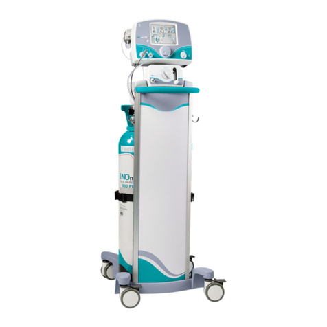
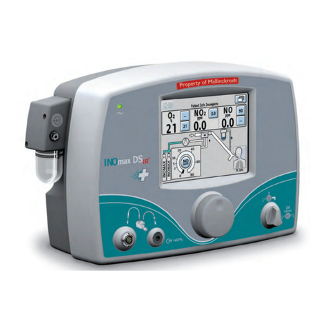
INOmax DSIR
The INOmax DSIR has an interface using infrared (IR) technology
which will allow the INOmax DSIR to communicate with the INOmeter®
(which is mounted to each INOMAX®cylinder).
The INOmax DSIR cart (PN 10018) has a cover with an infrared
transceiver mounted directly above each INOMAX cylinder. When
INOMAX cylinders are loaded, communication will take place between
the INOmax DSIR and the INOmeter after the boot up phase of the
INOmax DSIR is complete. A cylinder icon will be displayed on the
main screen when an INOMAX cylinder is recognized by the
INOmax DSIR.
INOmax DSIR Transport Regulator/Cap Assembly
This assembly is used during medical transport to provide pressurized
INOMAX to the INOmax DSIR as well as communicate INOMAX use
information via Infrared transceivers between the INOmax DSIR
(PN 10007) and the INOmeter.
The transport cap assembly provides Infrared technology molded in
the cap. This allows the INOmax DSIR to communicate via Infrared
with the INOmeter, which is mounted to each INOMAX cylinder.

3Part No. 20728 Rev-01
2012-09
Denitions
INOmeter - The factory installed INOmeter is designed for use
with INOMAX cylinders only. This time-metric device records the
amount of time the cylinder valve is opened.
iButton – Raised silver data port on the side of the INOmeter.
Symbols
Infrared Input/Output
Mallinckrodt, the “M” brand mark and the Mallinckrodt
Pharmaceuticals logo are trademark of a Mallinckrodt company.
Other brands are trademarks of a Mallinckrodt company or their
respective owner. ©2016 Mallinckrodt

4
Part No. 20728 Rev-01
2012-09
Contents
Pre-Use Checkout .....................................................................................5
Backup INOMAX Delivery .......................................................................12
Transport Regulator/Cap Assembly.........................................................14
Oxygen Dilution Chart .............................................................................18
INOMAX Cylinder 88-size Duration Chart ...............................................19
INOMAX Cylinder D-size Duration Chart.................................................20
Connection to Various Breathing Systems ..............................................22
A-Plus Medical Babi-Plus Bubble CPAP........................................... 23
Bagging Systems While Using the Injector Module ...........................24
Bunnell Life Pulse High Frequency Ventilator Circuit ........................28
Connecting INOmax DSIR Sample Tee to the Bunnell Life
Pulse Circuit..................................................................................30
Connecting INOmax DSIR Injector Module to the Bunnell Life
Pulse Circuit..................................................................................30
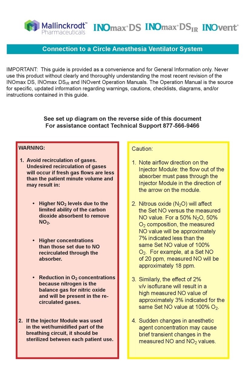
Circle Anesthesia System ..................................................................31
Fisher & Paykel Healthcare Bubble CPAP.........................................32
Fisher & Paykel Healthcare Infant Circuit Nasal Cannula .................33
Fisher&PaykelHealthcareOptiowBreathingCircuit......................34
Hamilton Arabella Nasal CPAP..........................................................35
ICU Ventilator Circuit .........................................................................36
Sensormedics 3100A/B High Frequency Oscillatory Ventilator
with a Filtered Circuit ....................................................................37
Sensormedics 3100A/B High Frequency Oscillatory Ventilator
with a Rigid or Flexible Circuit.......................................................38
Spontaneous Breathing Patient on a Mask Circuit ............................39
Spontaneous Breathing Patient on a Nasal Cannula ........................40
TeleexMedicalComfortFloHumidicationSystem.........................41
Transport Ventilator Circuit ................................................................42
Vapotherm 2000i................................................................................46
Vapotherm Precision Flow .................................................................47
Viasys Infant Flow CPAP System; Cardinal Airlife nCPAP System........... 48
Viasys Infant Flow SiPAP...................................................................49
INOblender Circuit Connection................................................................50
Fisher & Paykel Healthcare Neopuff Resuscitator.............................51
Changing INOMAX Cylinders..................................................................52
High Calibration Connection Diagrams ...................................................56
INOmax DSIR Disposable Adapters.........................................................58

5Part No. 20728 Rev-01
2012-09
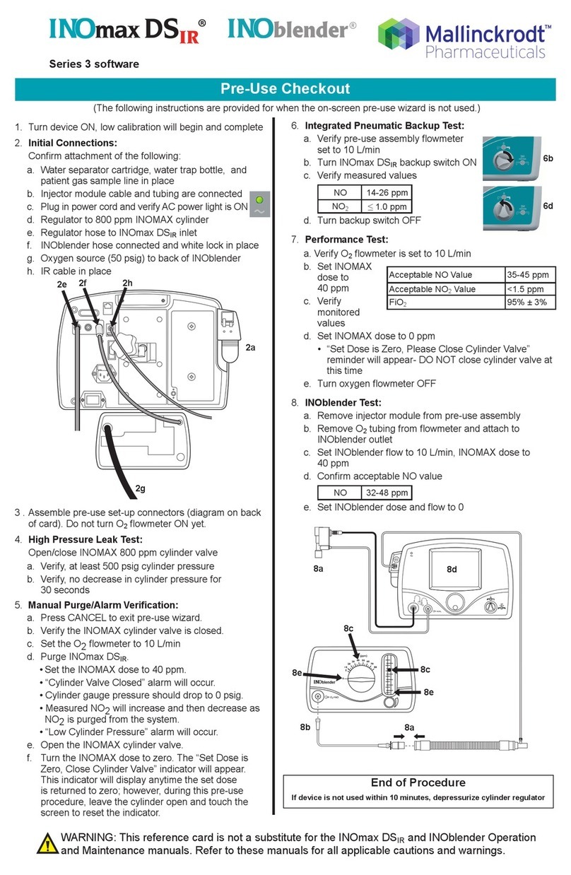
Pre-Use Checkout Outline
A. Initial Connections
B. High Pressure Leak Test
C. Low Range Calibration
D. Purge and Alarm Verication
E. Backup INOMAX Delivery Test
F. INOmax DSIR Performance Test
G. INOblender Test
Pre-Use Checkout

6
Part No. 20728 Rev-01
2012-09
A. Initial Connections
1. Check white plastic tip.
2. Connect high pressure regulator.
Pre-Use Checkout

7Part No. 20728 Rev-01
2012-09
Pre-Use Checkout
3. Connect the INOMAX regulator hose to one of the
INOMAX inlets
4. Connect the INOblender inlet hose to the INOmax DSIR
blender outlet
5. Connect the infrared cable to the back of the INOmax DSIR
6. Connect the oxygen hose to the INOblender oxygen inlet
7. Ensure the water separator cartridge/water trap bottle/
sample line and injector module are all in place
8. Turn INOmax DSIR ON, verify
speaker function.
7
7
7
6
8
3 4 5

8
Part No. 20728 Rev-01
2012-09
B. Perform High Pressure Leak Test
Wait 30 seconds and ensure
no pressure drop.
C. Perform Low Range Calibration
(Open/Close INOMAX
cylinder valve)
(second menu level)
Pre-Use Checkout
Note: Once the calibration is completed (bars turn green
and single tone sounds) press the menu button
twice to return to the main screen.
Note: Make sure INOmax
DSIR backup and
INOblender are OFF.

9Part No. 20728 Rev-01
2012-09
D. Perform Purge and Alarm Verication
Pre-Use Checkout
1. O2Flowmeter (Connected to wall/tank)
2. O2Tubing
3. 15M x 4.5mm Adapter
4. 22M / 15F x 22M / 15F Adapter
5. Injector Module
3
1
10 98
25
47
6
6. 300mm of 22mm Hose
7. Gas Sample Tee
8. Patient Gas Sample Line
withNaon
9. NO/N2Injector Tube
10. Injector Module Electrical Cable
(Assemble connectors and tubing as shown)
1. Ensure cylinder valve is closed.
2. Set O2owmeterto10L/min.
3. Purge INOmax DSIR.
a. Set INOMAX dose to 40 ppm
b. “Cylinder Valve Closed” alarm will occur
c. Cylinder gauge pressure should drop to 0 psig
d. Purge is complete when “Low NO/N2Pressure” alarm activates
4. Open cylinder valve.
5. Turn INOMAX dose to zero (note: The “Set Dose is Zero, Close
Cylinder Valve” indicator will appear).

10
Part No. 20728 Rev-01
2012-09
F. Complete INOmax DSIR Performance Test
1. Ensure oxygen ow of 10 L/min.
2. Set INOMAX dose to 40 ppm
and allow values to stabilize.
3. Verify values (see table).
4. Turn the INOMAX dose to zero.
NO = 14-26 ppm
NO2= <1.0 ppm
Set Dose
Acceptable NO
Value
Acceptable NO2Value
FiO2
40 ppm
35-45
ppm
<1.5 ppm
95% ±3%
1. Turn backup delivery ON.
2. Verify “Backup ON”
alarm activates.
3. Verify values.
4. Turn backup delivery OFF.
E. Perform Backup INOMAX Delivery Test
Pre-Use Checkout

11 Part No. 20728 Rev-01
2012-09
Acceptable NO Value 32 - 48 ppm
G. Perform INOblender Test
End of Pre-Use Checkout
Pre-Use Checkout
Note: Ensure INOblender inlet hose is connected to the back of
the INOmax DSIR and the quick-connect cover is in place.
1. Remove the Pre-Use set-
up oxygen tubing from
theoxygenowmeterand
connect it to the front of
the INOblender.
2. Remove the Injector
Module from the Pre-Use
set-up and reconnect
adapters.
3. On the INOblender, set
INOMAX dose to 40 ppm
and O2owto10L/min.
4. Verify values on the
INOmax DSIR.
5.Turnthedoseandow
to zero and remove the
Pre-Use set-up from the
INOblender.
The INOmax DSIR is now ready to connect to the patient.
• Set the INOMAX dose to be delivered to the patient.
• Set the appropriate alarm settings on the INOmax DSIR and
breathing device.
WARNING: If not starting therapy within 10 minutes,
depressurize the INOMAX regulator.
10 L/min
4
1
2
3
5
5
2
3
40 ppm

12
Part No. 20728 Rev-01
2012-09
WARNING:
When the backup NO delivery mode is used, a ow of
at least 5.0 L/min should be present in the ventilator
circuit to avoid INOMAX concentrations greater than
40 ppm.
The backup is intended for short term use when the
electronic delivery system fails until a replacement
NO delivery can be brought to the bedside.
If the backup is on, along with the main delivery
system an INOMAX value greater than set will be
delivered (a high priority alarm will be present).
The backup mode delivers a variable concentration
of NO to the patient depending on the ventilator ow
being used. See table below for details.
The table below indicates the nominal concentrations
delivered for different ventilator gas ows.
Backup INOMAX
Delivery
Ventilator/Gas
Flow (L/min) 5 7.5 10 15 20
NO
Concentration
(ppm)
40 27 20 13 10
INOMAXcylinderconc.X0.25L/min/ventilatorow=delivereddose

13 Part No. 20728 Rev-01
2012-09
Thebackupdeliveryprovidesaxedowof250mL/minofINOMAX
directly into the ventilator circuit through the Injector Module.
Backup NO delivery is completely pneumatic and is not reliant on the
operation of the main system.
Backup delivery mode OFF.
Backup delivery mode ON (with a Low Priority alarm).
Backup INOMAX
Delivery

14
Part No. 20728 Rev-01
2012-09
Transport Regulator/
Cap Assembly
Figure 1 Figure 2
Transport Regulator/Cap Assembly
WARNING:
• A new INOMAX cylinder and regulator must be purged
before use to ensure the patient does not receive greater
than 1.0 ppm of NO2.
• Loss of communication between the INOmax DSIR and the
INOMAX cylinder for more than one hour will result in
interruption of INOMAX delivery.
Caution: When using the Transport Regulator/Cap Assembly
(PN 10022) ensure the cap is in place on the cylinder
and the infrared cable is connected to the infrared
connector port on the back of the INOmax DSIR.
Note: Check the INOMAX cylinder for the correct product identity
labels, cylinder concentration and expiration date. Ensure
the INOMAX gas cylinder has more than 200 psig.
Step One
Note: Ensure the white plastic tip is in place on the regulator
connector and not chipped or cracked (see Figure 2).
Connect a high
pressure regulator
to an INOMAX
cylinder and tighten
thettingtothe
INOMAX cylinder
(see Figure 1).

15 Part No. 20728 Rev-01
2012-09
Transport Regulator/
Cap Assembly
Figure 3
Figure 4
Step Two
Connect the INOMAX
regulator hose to one of
the INOMAX inlets on the
back of the INOmax DSIR
(see Figure 3).
Step Three
Connect the Infrared cable from the
Transport Regulator/Cap Assembly
to the back of the INOmax DSIR
(see Figure 4).

16
Part No. 20728 Rev-01
2012-09
iButton
The electrical
cord exits the
cap directly
above the
iButton
keyway
-CLOSE +OPEN
Figure 5 Figure 6
Figure 7 Figure 8
Transport Regulator/
Cap Assembly
Step Four
Place the Cap Assembly over the INOmeter (see Figure 5).
Note: Be sure to align the keyway inside the Cap Assembly with the
iButton on the INOmeter (see Figure 5 and 6).
Step Five
Grasp the Cap Assembly to open cylinder valve (see Figure 7 and 8).

17 Part No. 20728 Rev-01
2012-09
Figure 9
Transport Regulator/
Cap Assembly
Final Set-up Diagram
The following diagram and photo illustrates all of the components connected.
Additional Information
Communication will take place between the INOmax DSIR and the
INOmeter after the boot up phase of the INOmax DSIR is complete.
Note: Cylinder icons are not visible and the dose control button
will remain inactive until the INOmax DSIR recognizes an
INOMAX cylinder.
Note: When using the Transport
Regulator/Cap Assembly
only one cylinder will be
displayed (see Figure 9).
Proceed with the
INOmax DSIR Pre-Use
Checkout
(see page 6)

18
Part No. 20728 Rev-01
2012-09
Oxygen Dilution Chart
For delivery with 800 ppm cylinder of
INOMAX (nitric oxide) for inhalation.
(Illustrative Only)
Caution FiO2 less than 21%
Please Note:
The calculations on this chart have been determined based on an
800 ppm cylinder of INOMAX (nitric oxide) for inhalation.
This chart is representative of a range of doses available on the
INOmax DSIR and doses higher than 20 ppm are not intended as the
recommended therapeutic dose.
Calculations are considered estimates and may vary under clinical
conditions.
All numbers have been rounded to the nearest hundredth.
0.21
0.20
0.20
0.19
0.40
0.39
0.38
0.36
0.59
0.59
0.57
0.54
0.79
0.78
0.76
0.72
.21 .40 .60 .80
Set FiO2
10
20
40
80
1.00
0.99
0.98
0.95
0.90
Actual FiO2
!
!
!
INOMAX Dose

19 Part No. 20728 Rev-01
2012-09
For an 88-Size 800 ppm Cylinder Concentration*
(Illustrative Only)
* All calculations for the table above are based on a full cylinder of 2000 psig,
1963 liters “88” cylinder, and also accounting for cylinder change at 200 psig. The
guresarecalculatedontotalcontinuousowcylinderconversionfactor0.98.
•INOMAXow=[DesireddoseXtotalventilatorow]/
[Cylinderconcentration-desireddose]
• Cylinder volume = Cylinder conversion factor X cylinder pressure psig
• Cylinder duration = Cylinder volume / INOMAXowrate
Calculations are considered estimates and may vary under clinical
circumstances. For more information, call 1-877-KNOW-INO (1-877-566-9466).
INOMAX Cylinder 88-Size
Duration Chart
(88-size)
This chart is representative of a range of doses available
on the INOmax DSIR and doses higher than 20 ppm are not
intended as the recommended therapeutic dose.
INOMAX Dose
5
ppm
10
ppm
20
ppm
40
ppm
80
ppm
43.3
Days
21.5
Days
10.6
Days
5.2
Days
2.4
Days
21.7
Days
10.7
Days
5.3
Days
2.6
Days
29
Hours
10.8
Days
5.4
Days
2.6
Days
31
Hours
14
Hours
5.4
Days
2.7
Days
31
Hours
15
Hours
7
Hours
FLOW
5
L/min
10
L/min
20
L/min
40
L/min

20
Part No. 20728 Rev-01
2012-09
Duration Chart
(D-size)
7.8
Days
3.9
Days
45
Hours
22
Hours
10
Hours
3.9
Days
46
Hours
22
Hours
11
Hours
5
Hours
46
Hours
23
Hours
11
Hours
5
Hours
2
Hours
23
Hours
11
Hours
5
Hours
2
Hours
1
Hour
5
L/min
10
L/min
20
L/min
40
L/min
FLOW
5
ppm
10
ppm
20
ppm
40
ppm
80
ppm
INOMAX Dose
* All calculations for the table above are based on a full cylinder of 2000 psig,
353 liter “D” cylinder, and also accounting for cylinder change at 200 psig. The
guresarecalculatedontotalcontinuousowcylinderconversionfactor0.18.
•INOMAXow=[DesireddoseXtotalventilatorow]/
[Cylinderconcentration-desireddose]
• Cylinder volume = Cylinder conversion factor X cylinder pressure psig
• Cylinder duration = Cylinder volume / INOMAXowrate
Calculations are considered estimates and may vary under clinical
circumstances. For more information, call 1-877-KNOW-INO (1-877-566-9466).
This chart is representative of a range of doses available
on the INOmax DSIR and doses higher than 20 ppm are not
intended as the recommended therapeutic dose.
For a D-Size 800 ppm Cylinder Concentration*
(Illustrative Only)
INOMAX Cylinder D-Size
Typically used in transport
Other manuals for INOmax DSIR
2
Table of contents
Other Mallinckrodt Medical Equipment manuals

Mallinckrodt
Mallinckrodt NELLCOR NPB-195 User manual

Mallinckrodt
Mallinckrodt INOblender 10026 User manual

Mallinckrodt
Mallinckrodt Nellcor N-20 User manual

Mallinckrodt
Mallinckrodt INOmax DSIR User manual

Mallinckrodt
Mallinckrodt INOmax DS User manual

Mallinckrodt
Mallinckrodt INOmax DS IR User manual

Mallinckrodt
Mallinckrodt Nellcor N-20PA User manual

Mallinckrodt
Mallinckrodt INOMAX DSir Plus User manual

Mallinckrodt
Mallinckrodt INOmax DSIR User manual