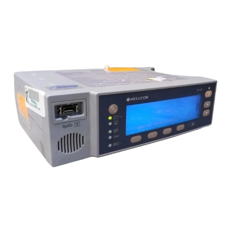
Mallinckrodt Nellcor N-20PA User manual

Caution: Federal law (U.S.A.) restricts this device to sale by or on the order of a physician.
To contact Mallinckrodt’s representative: In the United States, call 1.800.635.5267 or 314.654.2000; outside the United States, call
your local Mallinckrodt representative.
0123
2000 Mallinckrodt Inc. All rights reserved. 062153A-0500
SERVICE MANUAL
N-20PA Portable Pulse Oximeter

Mallinckrodt Inc.
675 McDonnell Boulevard
P.O. Box 5840
St. Louis, MO 63134 USA
Tel 314.654.2000
Toll Free 1.800.635.5267
Mallinckrodt Inc.
Europe BV
Hambakenwetering 1
5231 DD's-Hertogenbosch
The Netherlands
Tel +31.73.6485200
Nellcor Puritan Bennett Inc.
4280 Hacienda Drive
Pleasanton, CA 94588 USA
Nellcor Puritan Bennett Inc. is a wholly owned subsidiary of Mallinckrodt Inc. Nellcor and Nellcor Puritan Bennett are
trademarks of Mallinckrodt Inc.
To obtain information about a warranty, if any, for this product, contact Nellcor Technical Services or your local Nellcor
representative.
Covered by one or more of the following U.S. Patents and corresponding foreign patents: 4,621,643; 4,685,464; 4,700,708;
and 4,770,179

iii
CONTENTS
Contents...................................................................................................................................................................iii
Figures..................................................................................................................................................................... iv
Tables ....................................................................................................................................................................... v
SECTION 1: Introduction....................................................................................................................................1-1
1.1 Manual Overview..........................................................................................................................................1-1
1.2 Warnings, Cautions, and Notes.....................................................................................................................1-1
1.3 Description of the N-20PA Portable Pulse Oximeter ...................................................................................1-1
SECTION 2: Routine Maintenance.....................................................................................................................2-1
2.1 Overview .......................................................................................................................................................2-1
2.2 Cleaning........................................................................................................................................................2-1
2.3 Periodic Safety and Functional Checks........................................................................................................2-1
2.4 Battery...........................................................................................................................................................2-1
SECTION 3: Performance VERIFICATION..................................................................................................... 3-1
3.1 Introduction ..................................................................................................................................................3-1
3.2 Required Tools and Equipment.....................................................................................................................3-1
3.3 Performance Tests ........................................................................................................................................3-1
SECTION 4: Troubleshooting .............................................................................................................................4-1
4.1 Introduction ..................................................................................................................................................4-1
4.2 How to Use This Section...............................................................................................................................4-1
4.3 Who Should Perform Repairs .......................................................................................................................4-1
4.4 Replacement Level Supported.......................................................................................................................4-1
4.5 Obtaining Replacement Parts.......................................................................................................................4-1
4.6 Troubleshooting Guide .................................................................................................................................4-1
SECTION 5: Disassembly Guide ......................................................................................................................... 5-1
5.1 Introduction ..................................................................................................................................................5-1
5.2 Beginning Disassembly.................................................................................................................................5-1
5.3 Disassemblying the Printer/Flex Circuit Assembly.......................................................................................5-4
SECTION 6: Spare Parts .....................................................................................................................................6-1
6.1 Introduction ..................................................................................................................................................6-1
6.2 Spare Parts List ............................................................................................................................................6-1
SECTION 7: Packing for Shipment .................................................................................................................... 7-1
7.1 General Instructions .....................................................................................................................................7-1

CONTENTS
iv
7.2 Repacking in Original Carton ......................................................................................................................7-1
7.3 Repacking in a Different Carton...................................................................................................................7-1
SECTION 8: Specifications..................................................................................................................................8-1
8.1 Performance..................................................................................................................................................8-1
8.2 Alarms...........................................................................................................................................................8-1
8.3 Electrical.......................................................................................................................................................8-2
8.4 Environmental............................................................................................................................................... 8-2
8.5 Physical.........................................................................................................................................................8-3
SECTION 9: Technical Supplement.................................................................................................................... 9-1
9.1 Introduction ..................................................................................................................................................9-1
9.2 Functional Overview.....................................................................................................................................9-1
9.3 Definition of Terms .......................................................................................................................................9-5
9.4 Overall Block Diagram.................................................................................................................................9-6
9.5 SpO2Analog Circuitry .................................................................................................................................9-6
9.6 Digital Circuitry..........................................................................................................................................9-12
9.7 Circuit Illustrations.....................................................................................................................................9-31
FIGURES
Figure 5-1: Sensor Lock, Printer, Paper, and Battery Access Doors......................................................................... 5-1
Figure 5-2: N-20PA Covers with the PCB and Display Assembly ............................................................................5-2
Figure 5-3: Main, Auxiliary, and Display PCB Assembly .........................................................................................5-3
Figure 5-4: Printer and Flex Circuit Assembly..........................................................................................................5-4
Figure 9-1: Overall Block Diagram...........................................................................................................................9-1
Figure 9-2: SpO2 Analog Block Diagram..................................................................................................................9-2
Figure 9-3: N-20PA Hardware Block Diagram..........................................................................................................9-3
Figure 9-4: Power Supply Block Diagram .................................................................................................................9-4
Figure 9-5: Display Control Block Diagram .............................................................................................................. 9-4
Figure 9-6: Printer Control Block Diagram................................................................................................................9-5
Figure 9-7: SpO2 Analog Circuitry Block Diagram...................................................................................................9-7
Figure 9-9: Differential Synchronous Demodulation Circuit ..................................................................................... 9-9
Figure 9-11: Variable Gain Circuit .......................................................................................................................... 9-10
Figure 9-12: Filtering Circuit ..................................................................................................................................9-11
Figure 9-14: Digital Circuitry Block Diagram ......................................................................................................... 9-13
Figure 9-16: Address Demultiplexing Circuit .......................................................................................................... 9-15
Figure 9-17: Address Decoding Circuit ................................................................................................................... 9-16
CONTENTS
v
Figure 9-18: CPU Memory Circuit .........................................................................................................................9-17
Figure 9-19: Input Port Circuit.................................................................................................................................9-18
Figure 9-21: Real-Time Clock Circuit ..................................................................................................................... 9-19
Figure 9-22: Audio Output Circuit...........................................................................................................................9-20
Figure 9-24: User Controls Circuit...........................................................................................................................9-23
Figure 9-27: Analog Reference Voltage Circuit.......................................................................................................9-26
Figure 9-28: Ambient Light Circuit..........................................................................................................................9-27
Figure 9-29: Ambient Temperature Circuit..............................................................................................................9-27
Figure 9-30: Battery Voltage Circuit........................................................................................................................9-28
Figure 9-31: Battery Type Circuit...........................................................................................................................9-28
Figure 9-8: LED Drive Circuit................................................................................................................................ 9-31
Figure 9-10: N-20PA HSO Timing Diagram .......................................................................................................... 9-31
Figure 9-13: AC Variable Gain Control Circuit......................................................................................................9-31
Figure 9-15: CPU Circuit........................................................................................................................................9-31
Figure 9-20: Output Port Circuit ............................................................................................................................. 9-31
Figure 9-23: Display Control Circuit ...................................................................................................................... 9-31
Figure 9-25: Power Supply Circuit .........................................................................................................................9-31
Figure 9-26: Power Control Circuit.........................................................................................................................9-31
Figure 9-32: Printer Interface Circuit......................................................................................................................9-31
Figure 9-33: Printer Flex Circuit............................................................................................................................. 9-31
Figure 9-34: N-20PA Main PCB Schematic Diagram ............................................................................................ 9-31
Figure 9-35: N-20PA Auxiliary PCB Schematic Diagram......................................................................................9-31
Figure 9-36: N-20PA Flex Circuit Schematic Diagram ..........................................................................................9-31
TABLES
Table 4-1 : Troubleshooting the N-20PA.................................................................................................................. 4-2

[Page intentionally left blank]

1-1
SECTION 1: INTRODUCTION
1.1 Manual Overview
1.2 Warnings, Cautions, and Notes
1.3 Description of the N-20PA Portable Pulse Oximeter
1.1 MANUAL OVERVIEW
This manual contains information for servicing the N-20PA portable pulse
oximeter. Only qualified service personnel should service this product. Before
servicing the device, read the operator’s manual carefully for a thorough
understanding of its operation.
1.2 WARNINGS, CAUTIONS, AND NOTES
This manual uses three terms that are important for proper operation of the
device: Warning, Caution, and Note.
1.2.1 Warning
A warning precedes an action that may result in injury or death to the patient or
user. Warnings are boxed and highlighted in boldface type.
1.2.2 Caution
A caution precedes an action that may result in damage to, or malfunction of, the
device. Cautions are highlighted in boldface type.
1.2.3 Note
A note gives information that requires special attention.
1.3 DESCRIPTION OF THE N-20PA PORTABLE PULSE OXIMETER
The NellcorN-20PA portable pulse oximeter provides noninvasive
measurement of, and continuous information about, the percent of oxygenated
hemoglobin compared with total hemoglobin and pulse rate. A pulse amplitude
indicator provides a qualitative indication of pulse activity and patient perfusion.
Patients are connected to the instrument by a Nellcor sensor. The sensor LEDs
are driven by the SpO2analog section, which also conditions the incoming
signals, and provides CPU-adjustable gain stages. The N-20PA CPU measures
the sensor’s analog outputs, continually controls the signal gain, and calculates
SpO2and pulse rate.
The N-20PA is automatically calibrated each time it is switched on, and
whenever a new sensor is connected; it sets sensor-specific calibration
coefficients by reading a calibration resistor in the sensor. Also, the intensity of
the sensor’s light sources are adjusted automatically to compensate for
differences in tissue thickness and darkness.

Section 1: Introduction
1-2
Standard user controls consist of a measure button and a check-battery button.
The measure button signals the power control circuit to switch on the power
supply. The power supply then provides regulated power to the unit. Once power
is on, both the measure and check battery buttons are read by the CPU for user
commands.
The N-20PA printer provides a hard copy of acquired patient measurements.
The printer circuit includes three user control buttons: ON (on/off), ADV
(advance), and D/D (day/date). In addition, an ambient temperature sensor is
used with the battery voltage input to control printout quality.

2-1
SECTION 2: ROUTINE MAINTENANCE
2.1 Overview
2.2 Cleaning
2.3 Periodic Safety and Functional Checks
2.4 Batteries
2.1 OVERVIEW
The N-20PA requires no routine maintenance, routine service, or calibration. If
service is necessary, contact qualified service personnel or your local
Mallinckrodt representative. Use only Mallinckrodt-approved test equipment
when running a performance test on the N-20PA. The user's institution, local or
national agencies, or both may also require testing.
2.2 CLEANING
Dampen a cloth with a commercial, nonabrasive cleaner, and lightly wipe the
surfaces of the N-20PA. Do not spray or pour liquid on the instrument or
accessories. Do not allow liquid to contact connectors, switches, or openings in
the chassis.
2.3 PERIODIC SAFETY AND FUNCTIONAL CHECKS
The following checks should be performed at least every 2 years by a qualified
service technician.
Inspect the exterior of the N-20PA for damage.
Inspect safety labels for legibility. If the labels are not legible, contact Mallinckrodt
Technical Services Department or your local Mallinckrodt representative.
2.4 BATTERY
When the N-20PA is going to be stored for 3 months or more, remove the battery
prior to storage. To replace or remove the battery, refer to Section 5,
Disassembly Guide.

[Page intentionally left blank]

3-1
SECTION 3: PERFORMANCE VERIFICATION
3.1 Introduction
3.2 Required Tools and Equipment
3.3 Performance Tests
3.1 INTRODUCTION
This section describes performance verification and safety testing for the Nellcor
N-20PA pulse oximeter (monitor) and all options, following troubleshooting and
repairs.
The tests can be performed without removing the monitor cover. All tests except
Battery Operation must be performed before the monitor is returned to the user.
If the monitor fails to perform as specified in any test, repairs must correct the
discrepancy before the monitor is returned to the user.
The N-20PA is powered by alkaline batteries. The N-20PA design includes
built-in electrical isolation; no ground resistance or current leakage testing is
required. In addition, the N-20PA requires no calibration.
3.2 REQUIRED TOOLS AND EQUIPMENT
Durasensor Nellcor DS-100A
Oxisensor II Nellcor D-25
Tester, Pulse Oximeter Nellcor SRC-2 or SRC-1
Variable DC power supply; 1 amp supply, voltage range 0-6 VDC
3.3 PERFORMANCE TESTS
The procedures required to verify correct monitor performance are listed below:
3.3.1 Battery Performance
3.3.2 Power-Up Performance
3.3.3 Hardware and Software Tests
3.3.4 Backlight Test
3.3.5 Low Battery Test
3.3.6 Printer Test
The N-20PA will operate in diagnostic mode in conjunction with the Nellcor
pulse oximetry tester, model SRC-2 or SRC-1, to test instrument performance.
The SRC-2 plugs into the DB-9 sensor connector and uses the instrument’s
power supply and diagnostic software to test the display and the operation of the
instrument. Mallinckrodt recommends routine performance testing at 1-year
intervals. Refer to the SRC-2 operator’s manual for details on performance
testing with the SRC-2.

Performance Verification
3-2
To enter the diagnostic mode, connect the SRC-2 to the N-20PA while the
oximeter is off; then, turn the oximeter on. While in the diagnostic mode, a “d”
is displayed in the leftmost segment of the display. Note: No alarms sound while
in the diagnostic mode. Note also that, if the SRC-2 is disconnected while the
N-20PA is in diagnostic mode, the N-20PA shuts off automatically.
3.3.1 Battery Performance
This test is provided to verify that the monitor will operate for the period
specified.
The monitor is specified to operate on battery power as follows:
N-20/PA (with printer) 32 hours with Alkaline batteries.
This test requires a new set of batteries. Note that the batteries must be replaced
after the test.
1. Connect the Nellcor SRC-2 pulse oximeter tester to the monitor.
2. Set the switches on the SRC-2 as follows:
Switch Setting
RATE 38
LIGHT LOW
MODULATION LOW
RCAL/MODE RCAL 63/LOCAL
3. Momentarily press the MEASURE button, and then verify the following
power-up sequence:
a. All indicators--OXYGEN SATURATION, PULSE RATE, PULSE
SEARCH, LOW BATTERY, and the PULSE BARS--light for a few
seconds. Verify that the OXYGEN SATURATION and PULSE RATE
displays indicate "888."
b. The OXYGEN SATURATION display momentarily indicates the
monitor 3-digit software version. The other displays are not lit.
Software versions may vary depending on the date of manufacture.
The N-20PA will display the letters “PA” in the PULSE RATE display
while the software version is being displayed in the OXYGEN
SATURATION display.
c. The OXYGEN SATURATION display momentarily indicates the letters
”tSt” and the monitor sounds a single tone. The other displays are not lit.
“tSt” verifies that the monitor recognizes that a tester is connected.
d. The OXYGEN SATURATION and PULSE RATE displays indicate
“0,” the PULSE SEARCH indicator is flashing, and the PULSE BAR
will start to register the simulated pulse.
e. After a few beats, a pulse tone will be heard, and the PULSE SEARCH
indicator will turn off. The OXYGEN SATURATION display indicates
between 79 and 83 and the PULSE RATE display indicates between 37
and 39.
The N-20PA will indicate a “d” in the most significant digit (MSD) of
the OXYGEN SATURATION display when the SRC-2 is connected.

Performance Verification
3-3
4. The monitor must operate for at least 37 hours with no printer activity.
5. Verify that the LOW BATTERY indicator lights sometime after 35 hours of
operation.
6. Verify that the LOW BATTERY indicator starts flashing after 36 hours of
operation.
7. Verify that the monitor turns off approximately 1 hour after the LOW
BATTERY indicator starts flashing.
8. Allow the monitor to continue operation until power-down due to low
battery.
3.3.2 Power-up Performance
Monitors with the same software must demonstrate identical startup routines.
The power-up tests verify the following monitor functions:
3.3.2.1 Power-On Self-Test
3.3.2.2 Adult Defaults and Alarm Limit Ranges
3.3.2.3 Neonate Defaults and Alarm Limit Ranges
3.3.2.1 Power-On Self-Test
1. Place a new set of batteries in the monitor.
2. Do not connect a sensor or SRC-2 to the monitor.
3. Momentarily press the MEASURE button, and verify the following power-
up sequence:
a. All indicators--OXYGEN SATURATION, PULSE RATE, PULSE
SEARCH, LOW BATTERY, and the PULSE BARS--light for a few
seconds. Verify that the OXYGEN SATURATION and PULSE RATE
displays indicate "888."
b. The OXYGEN SATURATION display momentarily indicates the
monitor 3 -digit software version. The other displays are not lit.
Note: Software versions may vary depending on the manufacture date.
Note: The N-20PA will display the letters “PA” in the PULSE RATE display
while the software version is being dispalyed in the OXYGEN
SATURATION display.
c. The OXYGEN SATURATION and PULSE RATE display dashes “-” in
each window, the monitor sounds a single tone, and the PULSE
SEARCH indicator is flashing. The other displays are not lit.
4. Verify that the monitor automatically turns off after 60 seconds.
Change the SRC-2 to the switch configurations shown below, and verify monitor
operation using the chart shown below.

Performance Verification
3-4
SRC-2 Settings Monitor Indications
RATE LIGHT MODULATION SpO2PR
112 HIGH1 HIGH 81+ 2 112+ 2% (110 - 114)
201 LOW LOW 81+ 2 201+ 3% (195 - 207)
201 LOW HIGH 81+ 2 201+ 3% (195 - 207)
3.3.2.2 Adult Defaults and Alarm Limit Ranges
The following procedure will allow verification of the monitor’s adult factory
defaults, adjusting those defaults, and automatic reset to factory defaults.
1. Place a new set of batteries in the monitor.
2. Connect the DS-100A sensor to the monitor and place the sensor on a live
subject.
3. Press the MEASURE button, and verify the following power-up sequence:
a. All indicators--OXYGEN SATURATION, PULSE RATE, PULSE
SEARCH, LOW BATTERY, and the PULSE BARS--light for a few
seconds. Verify that the OXYGEN SATURATION and PULSE RATE
displays indicate "888."
b. The OXYGEN SATURATION display momentarily indicates the
monitor 3-digit software version. The other displays are not lit.
Note: Software versions may vary depending on the date of manufacture.
Note: The monitor will display the letters “PA” in the PULSE RATE display
while the software version is being displayed in the OXYGEN
SATURATION display.
c. The OXYGEN SATURATION and PULSE RATE display “0” in each
window, the monitor sounds a single tone, and the PULSE SEARCH
indicator is lit. The other displays are not lit.
d. The monitor will begin to track the pulse and after a few beats will
display the subject’s Oxygen Saturation and Pulse Rate.
If the subject’s OXYGEN SATURATION is below 91, select another
subject to facilitate the test procedure as written.
4. Press and hold the BATTERY CHECK button and then momentarily press
the DAY/DATE (D/D) button on the top of the monitor. Verify that the
following display is shown and that the “dashes” are flashing. The “H”
indicates that the High Alarm Limits can be set. The “dashes” in the SpO2
display indicate that the present setting is the Adult Default of 100% and
cannot be increased.

Performance Verification
3-5
SpO2%
/ min
-+
5. Press the PRINTER ON button and reduce the High Saturation Alarm limit
below the live subject’s value; typically 90 will be sufficient.
6. Momentarily press the DAY/DATE button and verify that the “90” in the
SpO2display stops flashing and the “170” starts flashing.
7. Press the PRINTER PAPER ADVANCE button and increase the High Rate
Alarm limit to 190.
8. Momentarily press the DAY/DATE button; then verify that the following
display is shown and that the “85” is flashing.
SpO2%
/ min
-+
9. Press the PRINTER ON button, and reduce the Low Saturation Alarm limit
to 80.
10. Momentarily press the DAY/DATA button, and verify that the “80” in the
SpO2display stops flashing and the “40” starts flashing.
11. Press the PRINTER ON button, and reduce the Low Rate Alarm limit to 30.
12. Momentarily press the DAY/DATE button and verify that the monitor
returns to the normal monitoring display and indicates the subject’s
saturation and pulse rate.
13. Verify that the monitor begins to alarm and that the SpO2reading begins to
flash.
14. Momentarily press the BATTERY TEST button, and verify that the alarm
remains silent for 2 minutes and that the SpO2reading continues to flash.
Note: The alarm may be silenced as necessary for remainder of the test.

Performance Verification
3-6
15. Press and hold the BATTERY CHECK button and then momentarily press
the DAY/DATE (D/D) button on the top of the monitor. Verify that the
following display is shown and that the “90” is flashing.
SpO2%
/ min
-+
16. Momentarily press the DAY/DATE button and verify that the “90” in the
SpO2display stops flashing and that the “190” Rate Default starts flashing.
17. Momentarily press the DAY/DATE button and verify that the following
display is shown and that the “80 “ is flashing.
SpO2%
/ min
-+
18. Momentarily press the DAY/DATE button and verify that the “80” in the
SpO2display stops flashing and that the “30” in the Rate Display starts
flashing.
19. Momentarily press the DAY/DATE button and verify that the monitor
returns to the normal monitoring display and indicates the live subject’s
saturation and pulse rate.
20. Press the MEASURE button until the monitor turns off.

Performance Verification
3-7
21. Press the MEASURE button, and verify the following power-up sequence:
a. All indicators--OXYGEN SATURATION, PULSE RATE, PULSE
SEARCH, LOW BATTERY, and the PULSE BARS --light for a few
seconds. Verify that the OXYGEN SATURATION and PULSE RATE
displays indicate "888."
b. The OXYGEN SATURATION display momentarily indicates the
monitor 3-digit software version. The other displays are not lighted.
Note: Software versions may vary depending on the type of monitor and the date
of manufacture.
The monitor will display the letters PA in the PULSE RATE display
while the software version is being displayed in the OXYGEN
SATURATION display.
c. The OXYGEN SATURATION and PULSE RATE displays “0” in each
window, the monitor sounds a single tone and the PULSE SEARCH
indicator is flashing. The other displays are not lit.
d. The monitor will begin to track the pulse and after a few beats will
display the subject’s Oxygen Saturation and Pulse Rate.
22. Press and hold the BATTERY CHECK button and then momentarily press
the DAY/DATE (D/D) button on the top of the monitor. Verify that the
following display is shown and that the dashes (“-“) are flashing. This
indicates the monitor has returned to the factory default settings.
SpO2%
/ min
-+
23. Momentarily press the DAY/DATE button and verify that the dashes (“-“) in
the SpO2display stop flashing and that the “170” Rate Default starts
flashing.
24. Momentarily press the DAY/DATE button and verify that the following
display is shown and that the “85” is flashing.

Performance Verification
3-8
SpO2%
/ min
-+
25. Momentarily press the DAY/DATA button and verify that the “85” in the
SpO2display stops flashing and that the “40” Rate Default starts flashing.
26. Momentarily press the DAY/DATE button and verify that the monitor
returns to the normal monitoring display and indicates the live subject’s
saturation and pulse rate.
27. Press the MEASURE button until the monitor turns off.
3.3.2.3 Neonate Defaults and Alarm Limit Ranges
The following procedure will allow verification of the monitor NEONATAL
factory defaults, adjusting those defaults, and automatic reset to factory Adult
defaults.
1. Place a set of batteries in the monitor. Verify that batteries are new.
2. Connect the DS-100A sensor to the monitor and place the sensor on a
live subject (adult subject is OK for this procedure).
3. Press and hold the BATTERY TEST button and press the MEASURE
button for at least 5 seconds, and then verify the following power-up
sequence:
a. All indicators—OXYGEN SATURATION, PULSE RATE, PULSE
SEARCH, LOW BATTERY, and the PULSE BARS--light for a few
seconds. Verify that the OXYGEN SATURATION and PULSE RATE
displays indicate "888."
b. The OXYGEN SATURATION display momentarily indicates the
monitor 3-digit software version. The other displays are not lit.
Note: Software versions may vary depending on the date of manufacture.
The monitor will display the letters PA in the PULSE RATE display
while the software version is being displayed in the OXYGEN
SATURATION display.
c. The OXYGEN SATURATION and PULSE RATE displays “0” in each
window, the monitor sounds a single tone, and the PULSE SEARCH
indicator is lit. The other displays are not lit.
An “n” will be displayed in the Most Significant Digit (MSD) of the
SpO2display, indicating the Neonatal mode.

Performance Verification
3-9
d. The monitor will begin to track the pulse and after a few beats will
display the subject’s Oxygen Saturation and Pulse Rate.
4. Press and hold the BATTERY CHECK button and then momentarily press
the DAY/DATE (D/D) button on the top of the monitor. Verify that the
following display is shown and that the “95” is flashing. The “H” indicates
that the High Saturation Alarm Limit can be set.
SpO2%
/ min
-+
5. Press the PRINTER ON button and reduce the High Saturation Alarm limit
to 90.
6. Momentarily press the DAY/DATE button and verify that the “90” in the
SpO2display stops flashing and that the “190” starts flashing.
7. Press the PRINTER PAPER ADVANCE button and increase the High Rate
Alarm limit to 205.
8. Momentarily press the DAY/DATE button to verify that the following
display is shown and that the “80” is flashing.
SpO2%
/ min
-+
9. Press the PRINTER ON button and reduce the Low Saturation Alarm limit
to 70.
10. Momentarily press the DAY/DATE button and verify that the “70” in the
SpO2display stops flashing and that the “90” starts flashing.
11. Press the PRINTER ON button and reduce the Low Rate Alarm limit to 80.

Performance Verification
3-10
12. Momentarily press the DAY/DATE button and verify that the monitor
returns to the normal monitoring display and indicates the live subject’s
saturation and pulse rate.
13. Press and hold the BATTERY CHECK button and then momentarily press
the DAY/DATE (D/D) button on the top of the monitor. Verify that the
following display is shown and that the “90” is flashing.
SpO2%
/ min
-+
14. Momentarily press the DAY/DATE button and verify that the “90” in the
SpO2 display stops flashing and that the “205” Rate Default starts flashing.
15. Momentarily press the DAY/DATE button and verify that the following
display is shown and that the “70 “ is flashing.
SpO2%
/ min
-+
16. Momentarily press the DAY/DATE button and verify that the “70” in the
SpO2display stops flashing and that the “80” in the Rate Display starts
flashing.
17. Momentarily press the DAY/DATE button and verify that the monitor
returns to the normal monitoring display and indicates the live subject’s
saturation and pulse rate.
18. Verify that the monitor begins to alarm and that the number representing the
live subject’s saturation and pulse rate begins to flash.
Table of contents
Other Mallinckrodt Medical Equipment manuals

Mallinckrodt
Mallinckrodt INOblender 10026 User manual

Mallinckrodt
Mallinckrodt INOmax DS IR User manual

Mallinckrodt
Mallinckrodt INOmax DSIR User manual

Mallinckrodt
Mallinckrodt INOmax DS User manual

Mallinckrodt
Mallinckrodt INOmax DSIR User manual

Mallinckrodt
Mallinckrodt Nellcor N-20 User manual

Mallinckrodt
Mallinckrodt INOmax DSIR User manual

Mallinckrodt
Mallinckrodt NELLCOR NPB-195 User manual

Mallinckrodt
Mallinckrodt INOMAX DSir Plus User manual