Malvern Hydro 2000 G User manual

INSTRUMENTS
Printed in England MRK0865-01
Malvern Instruments Limited
Enigma Business Park
Grovewood Road, Malvern
Worcs, WR14 1XZ, U.K.
Tel: +44 (0) 1684 892456
Fax: +44 (0) 1684 892789
www.malvern.com
user manual
Hydro 2000
G/S


Hydro 2000G/S
User Manual
MAN0385 Issue 1.0 March 2007
MAN0385-1.0 Hydro 2000G-S.book Page i Friday, March 16, 2007 4:02 PM

© Malvern Instruments Ltd. 2007
Malvern Instruments makes every effort to ensure that this document is correct. However, due to
Malvern Instruments’ policy of continual product development we are unable to guarantee the
accuracy of this, or any other document after the date of publication. We therefore disclaim all
liability for any changes, errors or omissions after the date of publication. No reproduction or
transmission of any part of this publication is allowed without the express written permission of
Malvern Instruments Ltd.
Head office:
Malvern Instruments Ltd.
Enigma Business Park,
Grovewood Road,
Malvern,
Worcestershire WR14 1XZ
United Kingdom.
Tel + [44] (0)1684-892456
Fax + [44] (0)1684-892789
Windows 2000 and XP are registered trademarks of the Microsoft Corporation.
Tygon is a registered trademark of Norton Co.
Perlast is a registered trademark of Precision Polymer Engineering.
Printed in England
MAN0385-1.0 Hydro 2000G-S.book Page ii Friday, March 16, 2007 4:02 PM

Hydro 2000G/S Page i
Part 1 - Operator’s Guide
Introduction to this manual
Introduction . . . . . . . . . . . . . . . . . . . . . . . . . . . . . . . . . . . . . . . . . . . . . . 1-1
Access to the instrument . . . . . . . . . . . . . . . . . . . . . . . . . . . . . . . . . . . . 1-2
Assumed information . . . . . . . . . . . . . . . . . . . . . . . . . . . . . . . . . . . . . . . 1-3
Where to get help . . . . . . . . . . . . . . . . . . . . . . . . . . . . . . . . . . . . . . . . . . 1-3
Hardware features
Introduction . . . . . . . . . . . . . . . . . . . . . . . . . . . . . . . . . . . . . . . . . . . . . . 2-1
What the dispersion unit does . . . . . . . . . . . . . . . . . . . . . . . . . . . . . . . . . 2-1
How the dispersion unit works . . . . . . . . . . . . . . . . . . . . . . . . . . . . . . . . 2-2
How the dispersion unit is controlled . . . . . . . . . . . . . . . . . . . . . . . . . . . . 2-3
Features of the Hydro 2000G . . . . . . . . . . . . . . . . . . . . . . . . . . . . . . . . . 2-3
Features of the Hydro 2000S. . . . . . . . . . . . . . . . . . . . . . . . . . . . . . . . . 2-11
Software features
Introduction . . . . . . . . . . . . . . . . . . . . . . . . . . . . . . . . . . . . . . . . . . . . . . 3-1
Making a measurement . . . . . . . . . . . . . . . . . . . . . . . . . . . . . . . . . . . . . 3-1
Manually controlling the dispersion unit . . . . . . . . . . . . . . . . . . . . . . . . . . 3-2
Writing an SOP for the dispersion unit . . . . . . . . . . . . . . . . . . . . . . . . . . . 3-5
Advanced software features: Vari-flow . . . . . . . . . . . . . . . . . . . . . . . . . . . 3-8
Table of Contents
MAN0385-1.0 Hydro 2000G-S.book Page i Friday, March 16, 2007 4:02 PM

Table of Contents Hydro 2000G/S
Page ii MAN 0385
Part 2 - Appendices
Specification
Hydro 2000G . . . . . . . . . . . . . . . . . . . . . . . . . . . . . . . . . . . . . . . . . . . . .A-1
Hydro 2000S . . . . . . . . . . . . . . . . . . . . . . . . . . . . . . . . . . . . . . . . . . . . .A-2
Purge air specification (Hydro 2000G) . . . . . . . . . . . . . . . . . . . . . . . . . . . A-2
Chemical compatibility
Introduction . . . . . . . . . . . . . . . . . . . . . . . . . . . . . . . . . . . . . . . . . . . . . . B-1
Regulatory statements
CE Declaration of Conformity (AWA2000) . . . . . . . . . . . . . . . . . . . . . . . . . C-2
CE Declaration of Conformity (AWA2001) . . . . . . . . . . . . . . . . . . . . . . . . . C-3
Index
MAN0385-1.0 Hydro 2000G-S.book Page ii Friday, March 16, 2007 4:02 PM

Part 1 -
Operator’s Guide
MAN0385-1.0 Hydro 2000G-S.book Page 1 Friday, March 16, 2007 4:02 PM

MAN0385-1.0 Hydro 2000G-S.book Page 2 Friday, March 16, 2007 4:02 PM

Hydro 2000G/S Page 1-1
1
Introduction
to this manual
Introduction
This manual describes the operation of the large volume Hydro 2000G and small
volume Hydro 2000S sample dispersion units:
This manual is a supplement to the following manuals:
Mastersizer 2000 User Manual (termed “the main User Manual”).
Mastersizer 2000 Essentials Manual (termed “the Essentials Manual”).
This dispersion unit manual focuses on some specific issues of the dispersion unit
that are not covered by the above manuals. It aims to:
Describe what the dispersion unit is and explain in simple terms how it works.
Identify the physical features of the dispersion unit.
Describe the software and explain how to use the dispersion unit to make a
measurement on the system.
Warning!
The dispersion unit or the samples to be measured may be hazardous if
misused. Users must read the Health and Safety information in the
Essentials Manual before operating the system.
We recommend that users who have never operated a Malvern particle analyser
before read this manual fully before starting the first measurement.
Instrument Model number
Hydro 2000G AWA2000
Hydro 2000S AWA2001
MAN0385-1.0 Hydro 2000G-S.book Page 1 Friday, March 16, 2007 4:02 PM

Chapter 1 Introduction to this manual
Page 1-2 MAN 0385
1
Those who are more familiar with particle size analysers may wish to jump straight
to Chapter 4 of the main User Manual which gives details on making measure-
ments. However, the importance of sample preparation before measurement can-
not be overstated so we recommend reading the chapter on sample preparation
(Chapter 8 of the main User Manual) as a priority.
Access to the instrument
Within this manual, reference is made to the various people who will have access to
the dispersion unit. Below is a list of these people and their responsibilities:
Malvern personnel
Malvern personnel (service engineers, representatives, etc.) have full access to the
dispersion unit and are authorised to perform all service procedures that may
require the removal of the covers.
Supervisor
The supervisor is the person responsible for the management/safety of the disper-
sion unit and of its operation. The supervisor is responsible for the training of the
operators. The supervisor can perform all user maintenance routines identified in
Chapter 4 of the Essentials Manual, including changing the fuses.
Warning!
The supervisor/operator must never remove the covers of the instrument
or dispersion unit. Removal of the covers by unauthorised personnel will
invalidate the warranty of the dispersion unit.
Operator
An operator is a person trained in the use of the dispersion unit. The operator can
perform all user maintenance routines identified in Chapter 4 of the Essentials
Manual, except for changing the fuses.
Warning!
Failure to follow this guideline could result in exposure to hazardous volt-
ages.
MAN0385-1.0 Hydro 2000G-S.book Page 2 Friday, March 16, 2007 4:02 PM

Introduction to this manual Chapter 1
Hydro 2000G/S Page 1-3
Assumed information
All pictures and text show the Hydro 2000G unless information is specific to the
Hydro 2000S.
Naming convention
Within this manual:
The Mastersizer 2000 optical bench is referred to as “the optical bench” or “the
instrument”.
The sample dispersion units are referred to in full (e.g. “the Hydro 2000G”) or
as “the dispersion unit”.
The combination of the optical bench, one or more dispersion units and the
computer is referred to as “the system”.
Menu commands
Menu commands from the Malvern software are referred to in the form main
menu-menu item. As an example, the command Configure-New SOP refers to
selecting the New SOP item in the Configure menu. The same rules apply for
sub-menus of sub-menus, so that Tools-Options-Instrument Port refers to the
Instrument Port item in the Options sub-menu, which itself is a sub-menu of
the Tools menu. Menu commands are always shown in bold text.
Where to get help
Full details on where and how to obtain help can be found in Chapter 1 of the
main User Manual.
The Essentials Manual gives information on the following:
Site requirements.
Health and Safety.
Maintenance.
Installation (in case the system has to be moved after its initial installation by
Malvern Instruments personnel).
MAN0385-1.0 Hydro 2000G-S.book Page 3 Friday, March 16, 2007 4:02 PM

Chapter 1 Introduction to this manual
Page 1-4 MAN 0385
MAN0385-1.0 Hydro 2000G-S.book Page 4 Friday, March 16, 2007 4:02 PM

Hydro 2000G/S Page 2-1
2
Hardware features
Introduction
This chapter describes the physical features of the dispersion unit. It covers:
What the dispersion unit does.
How the dispersion unit works.
How the dispersion unit is controlled.
The physical features of the Hydro 2000G in detail.
The physical features of the Hydro 2000S in detail.
What the dispersion unit does
The sole purpose of any sample dispersion unit is to prepare the sample and then
deliver it to the optical bench so that it can be measured.
The Hydro 2000G and Hydro 2000S allow the Mastersizer to be used for particle-
in-liquid particle sizing. Functionally, the two dispersion units are virtually identi-
cal except that the Hydro 2000G can circulate 800ml of liquid while the Hydro
2000S has a smaller capacity of 150ml. The small volume of the Hydro 2000S is
ideal when using solvent dispersants or when samples and dispersants are either
expensive or hazardous.
The materials used in the manufacture of the dispersion units maximise the range
of samples which can be handled. Variable pump/stirrer speeds allow a wide range
of particle sizes and densities to be suspended and circulated, whilst a variable
power ultrasonic system enables particle agglomerates to be dispersed.
MAN0385-1.0 Hydro 2000G-S.book Page 1 Friday, March 16, 2007 4:02 PM

Chapter 2 Hardware features
Page 2-2 MAN 0385
2
How the dispersion unit works
This is the Hydro 2000G:
ill 4911
The dispersion unit comprises a tank that holds one litre of sample/dispersant
liquid. A stirrer , controlled from the software, agitates the sample and stops it
from settling or separating out. The pump , controlled from the software, forces
the sample from the TO CELL port of the dispersion unit to the flow cell
located in the optical bench, via the sample tubing. The pump and stirrer can be
independently controlled.
The sample is pumped through the flow cell and then returns to the tank via the
sample tubing and the FROM CELL port .
An ultrasonic probe is provided to aid sample dispersion and can also be used to
remove bubbles from the flow path.
The dispersion unit contains two fluid handling valves controlled from the soft-
ware:
A motor-driven drain valve that allows the tank to be drained.
A dispersant valve that opens to allow clean dispersant into the tank.
The operation of the Hydro 2000S is virtually identical, except that it has a com-
bined pump/stirrer mechanism and a smaller (150ml) tank capacity.
2, 3
5
4
32 1 67
MAN0385-1.0 Hydro 2000G-S.book Page 2 Friday, March 16, 2007 4:02 PM
Hardware features Chapter 2
Hydro 2000G/S Page 2-3
How the dispersion unit is controlled
The dispersion unit is controlled using a single software dialogue with sliders for
the pump speed, stirrer speed and ultrasonic power (Chapter 3 has details). When
controlled through a Standard Operating Procedure (SOP), the software tells the
user what value to set for each parameter.
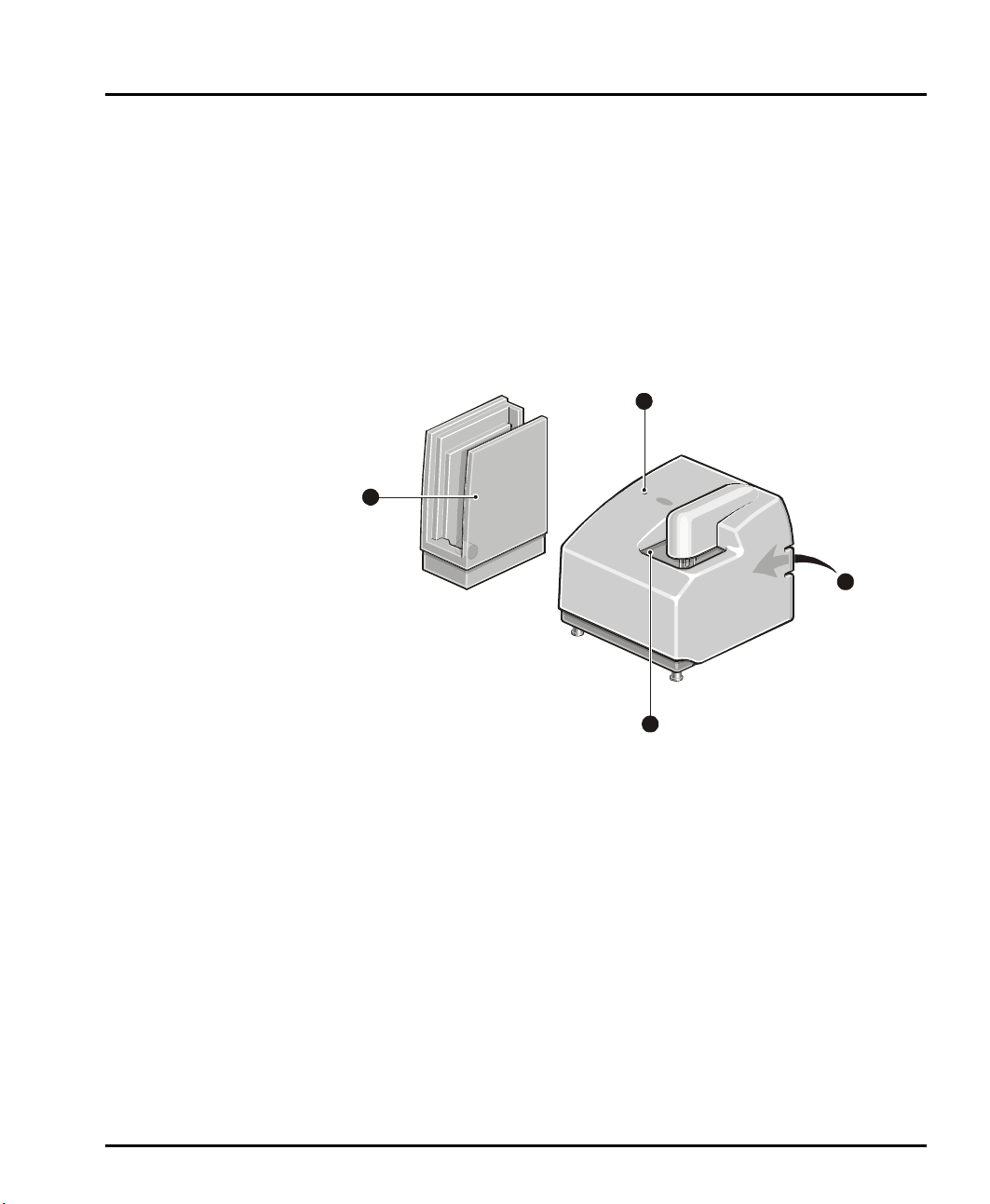
Features of the Hydro 2000G
This illustration identifies the main features of the dispersion unit:
ill 4912
These are the following:
Tank area
The tank holds the sample and dispersant. The pump and stirrer in the tank keep
the sample in suspension and continually circulate the sample and dispersant
through the flow cell. More details on the tank area are given below.
An ultrasonic probe also helps to disperse the sample. All functions of the tank area
are controlled by the Malvern software.
Status indicator
The status indicator illuminates in one of three colours when the dispersion unit is
powered up:
green if the dispersion unit is functioning correctly and its cell has been
loaded into the optical bench. (i.e. the dispersion unit is “active”)
4
3
2
1
MAN0385-1.0 Hydro 2000G-S.book Page 3 Friday, March 16, 2007 4:02 PM

Chapter 2 Hardware features
Page 2-4 MAN 0385
amber if the dispersion unit is functioning correctly but its cell has not been
loaded into the optical bench. (i.e. the dispersion unit is at “standby”)
red if the dispersion unit detects an error. If an error message does not appear
on the screen, selecting Configure-Accessory displays the accessory control
dialogue which should show the error.
Rear panel
The rear panel contains all services and communication connectors for the disper-
sion unit. More details on the rear panel are given later in this chapter.
Cell holder
The Mastersizer 2000 system is designed so that more than one dispersion unit can
be connected at once. The cell holder provides a convenient storage location for the
flow cell if another dispersion unit is in use.
The cell holder reduces the build up of dust on the cell windows when not in use.
If the cell is not used for short periods (up to 24 hours), leave the cell and tank full
of clean dispersant so that the cell windows do not dry out, leaving smears or water
marks on the window surface.
If the push on connectors are to be removed, the cell may be stored wet by using
the syringe supplied to fill it with clean dispersant.
If the cell is not to be used for longer periods, remove and dry the cell windows;
the Essentials Manual has details. The cell holder houses the window removing
tool in its base.
Tank area
As described above, the tank holds the sample and dispersant. The pump and stirrer
in the tank keep the sample in suspension and continually circulate the sample and
dispersant through the cell. This diagram identifies the features of the tank area:
ill 4914
1
3
4
5
3
2
1
MAN0385-1.0 Hydro 2000G-S.book Page 4 Friday, March 16, 2007 4:02 PM

Hardware features Chapter 2
Hydro 2000G/S Page 2-5
These are the following:
Tank
The tank can hold up to one litre of sample and dispersant for circulation through
the cell of the optical bench.
Warning!
Due to the possible risk of sonication of the blood and its unknown effects,
never place fingers in the tank when the ultrasonic probe is in operation.
Also, never put fingers in the tank when the pump/stirrer shaft is rotating.
Sample and dispersant can be poured directly into the tank. If this is done, do not
cause the tank to overflow by filling it too quickly. Clean any spillage off the covers
immediately to prevent damage.
Pump/stirrer
The stirrer, located in the base of the tank, agitates the sample/dispersant mixture.
The pump circulates the sample through the flow cell located in the sample area of
the optical bench. The pump and stirrer speeds are controlled independently by the
software.
Warning!
Never put fingers into the tank when the pump/stirrer shaft is rotating.
Caution!
Never operate the pump/stirrer at more than half speed with the tank
empty.
Ultrasonic probe
Warning!
Due to the possible risk of sonication of the blood and its unknown effects,
never put fingers in the tank when the ultrasonic probe is in operation.
The ultrasonic probe is used to help disperse samples. The power of the probe is
controlled through the software.
Level sensor
The level sensor automatically stops the tank being filled above a certain level. If
the tank fails to fill properly then the level sensor may require cleaning or the
MAN0385-1.0 Hydro 2000G-S.book Page 5 Friday, March 16, 2007 4:02 PM

Chapter 2 Hardware features
Page 2-6 MAN 0385
threshold settings may need adjusting. The Essentials Manual has more details
on cleaning the level sensor.
The level sensor must be set to detect different types of dispersant by setting the
level sensor threshold. This is done by selecting Configure-Accessories. The
Level Sensor Threshold section is shown below:
Use the up and down arrows to set the threshold for the dispersant used then click
the Apply button. The values of commonly used dispersants are listed below:
The level sensor threshold must always be set when a different dispersant is used.
Level sensor thresholds are also stored in the dispersant database.
Tank cover
The tank cover is there to protect the operator from splashes from the tank. Always
replace the cover after adding sample to the tank.
Water (default) 64%
White spirit 36%
Propan-2-ol 64%
2-2-4 Trimethyl pentane 36%
MAN0385-1.0 Hydro 2000G-S.book Page 6 Friday, March 16, 2007 4:02 PM
Hardware features Chapter 2
Hydro 2000G/S Page 2-7
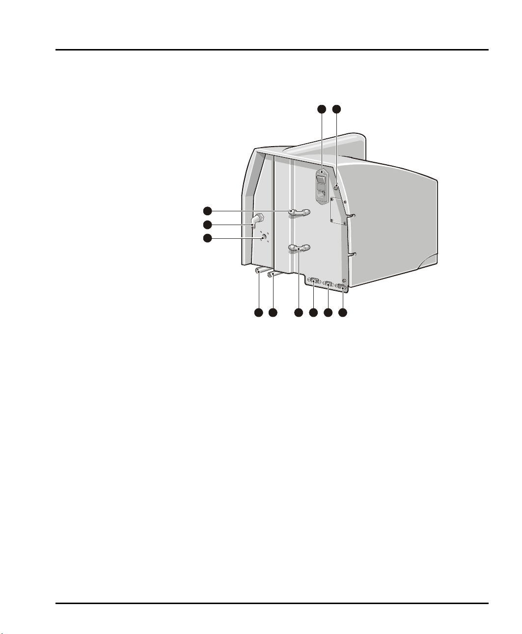
Rear panel
This illustration identifies the main features of the rear panel:
ill 4913
These are the following:
Drain
The drain port is the exit point where sample/dispersant leaves the dispersion unit.
A warning triangle warns that the contents of the tank are drained from this pipe.
The risk depends on the hazardous nature of the dispersants/samples being meas-
ured.
The drain pipe should not exceed 2m in length, must run downwards and should
have no loops or kinks.
Dispersant input port
The dispersant input is the inlet port which is connected to a clean source of dis-
persant. A warning triangle warns that the dispersant may be hazardous, though for
most applications it will be water.
Air purge inlet
If using a particularly aggressive dispersant, this may cause the grease in the pump
motor bearings to leach out. If this may be a problem, the air purge inlet port can be
used to connect an air supply. This will keep fumes away from the bearings. The air
supply must be maintained at all times when aggressive dispersants are used;
Appendix A gives the purge air supply specifications.
10
4
5
3
2 98
7
6
1
11
MAN0385-1.0 Hydro 2000G-S.book Page 7 Friday, March 16, 2007 4:02 PM

Chapter 2 Hardware features
Page 2-8 MAN 0385
Tank fill rate
This adjuster alters an internal pressure regulator that will control the rate at which
the tank is filled with dispersant. This is always set by the installation engineer but
if it’s found that the dispersant pressure has changed (one sign is that the tank takes
a long time to fill), alter this adjuster so that a fill tank cycle takes about 20 seconds.
“From cell” pipe
This is the sample return port where the sample/dispersant returns to the disper-
sion unit from the flow cell in the optical bench.
“To cell” pipe
This is the sample-out port where sample/dispersant leaves the dispersion unit for
the flow cell.
Mains power supply
The mains power supply is a standard IEC socket that supplies mains power to the
dispersion unit. It also houses the dispersion unit’s fuses and its on/off switch.
Accessory comms “in” connector
The communications cable from the optical bench or from another dispersion unit
connects here.
Accessory comms “out” connector
If more than one dispersion unit is connected to the system and this is the first dis-
persion unit in-line then a communication cable will be connected from this con-
nector to the accessory comms - “in” connector of the second dispersion unit.
The termination plug supplied with the optical bench must be fitted here if this is
the only dispersion unit connected or it is the last dispersion unit in the line.
Auxiliary connector
Not used.
Manual drain
The manual drain button can be pressed to drain the tank (the dispersion unit must
be powered up first). Users may wish to do this if, for example, they need to drain
the dispersion unit without having to turn on the control software. Pressing and
holding the button will open the drain valve. Releasing the button will close the
drain valve.
MAN0385-1.0 Hydro 2000G-S.book Page 8 Friday, March 16, 2007 4:02 PM
This manual suits for next models
1
Table of contents
Other Malvern Measuring Instrument manuals

Malvern
Malvern Mastersizer 3000 User manual

Malvern
Malvern Mastersizer Series User manual

Malvern
Malvern Zetasizer Nano Series User manual

Malvern
Malvern Hydro 2000uP User manual

Malvern
Malvern Zetasizer Nano Series User manual

Malvern
Malvern Scirocco 2000 User manual

Malvern
Malvern NANOSIGHT NS300 User manual

Malvern
Malvern NANOSIGHT NS300 User manual


