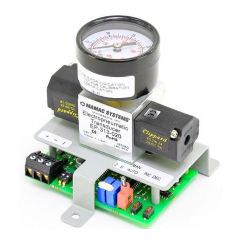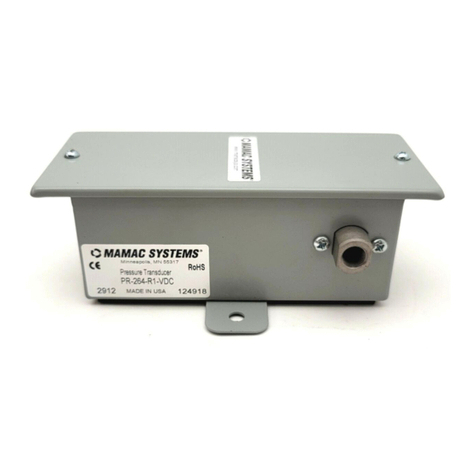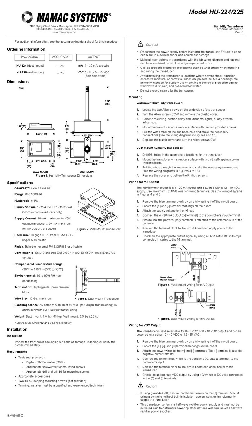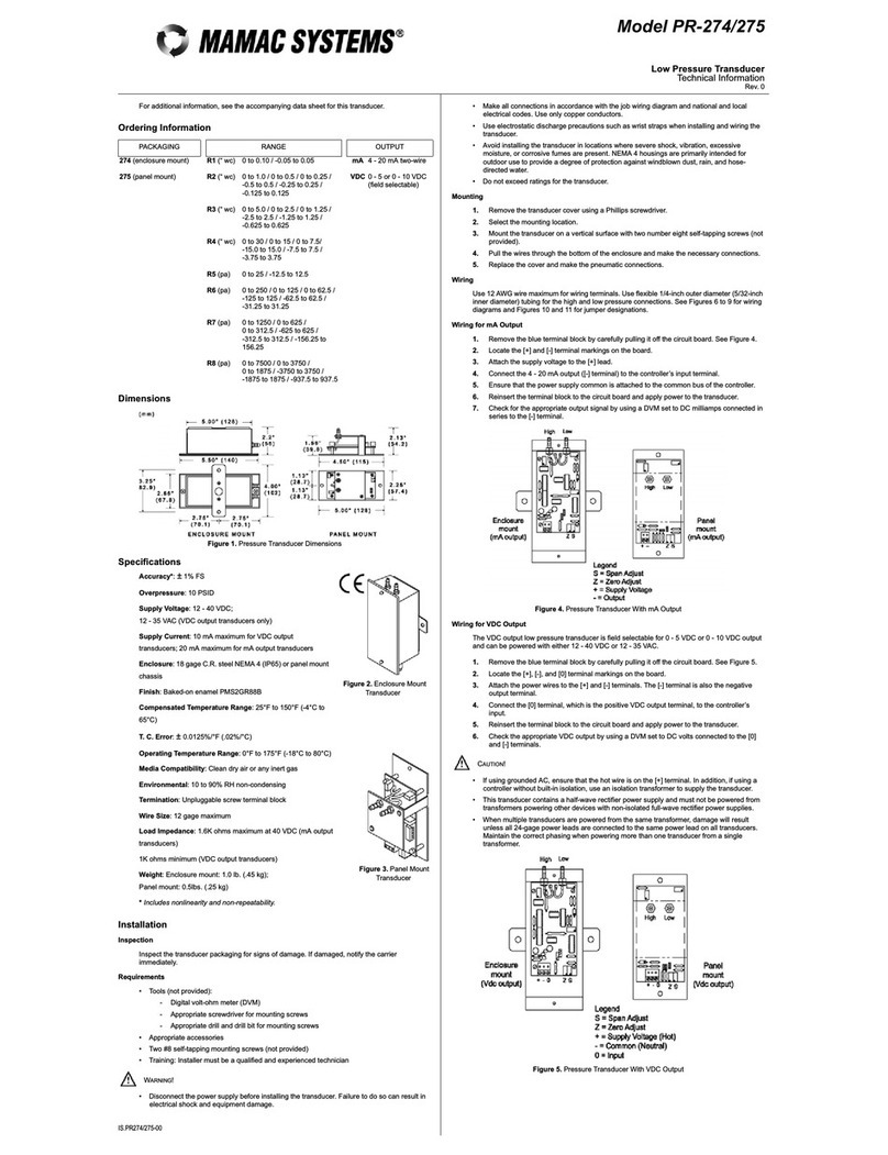
ModelEP-311/313
TechnicalInformatio
TI.EP311/313-01
7400 Flying Cloud Drive •Minneapolis,MN55344-3720 •USA
800-843-5116 •612-835-1626 •Fax 612-829-5331
sales@mamacsys.com•www.mamacsys.comElectropneumaticTransduce
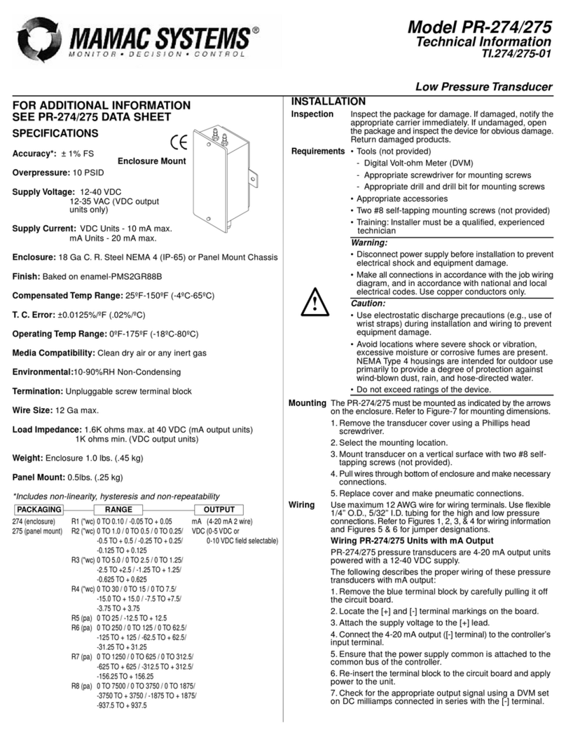
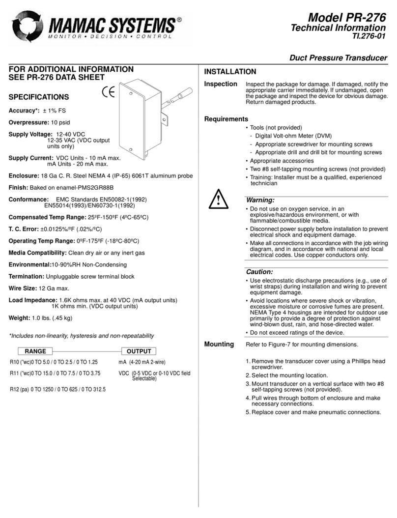
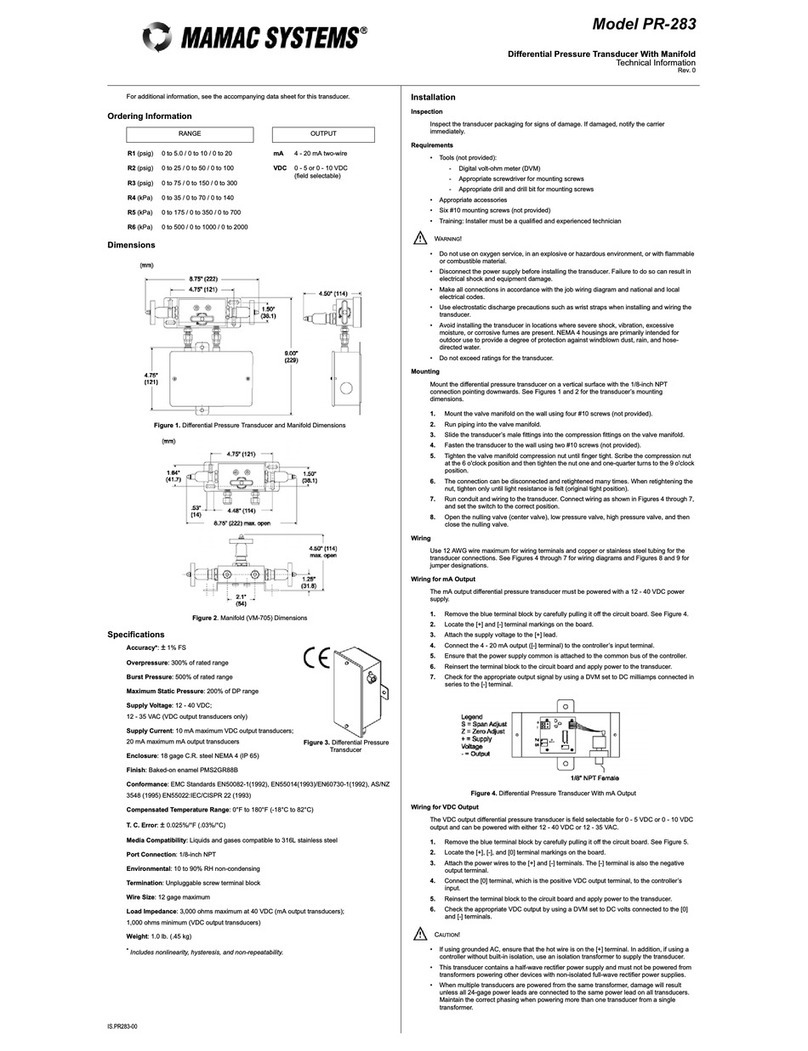
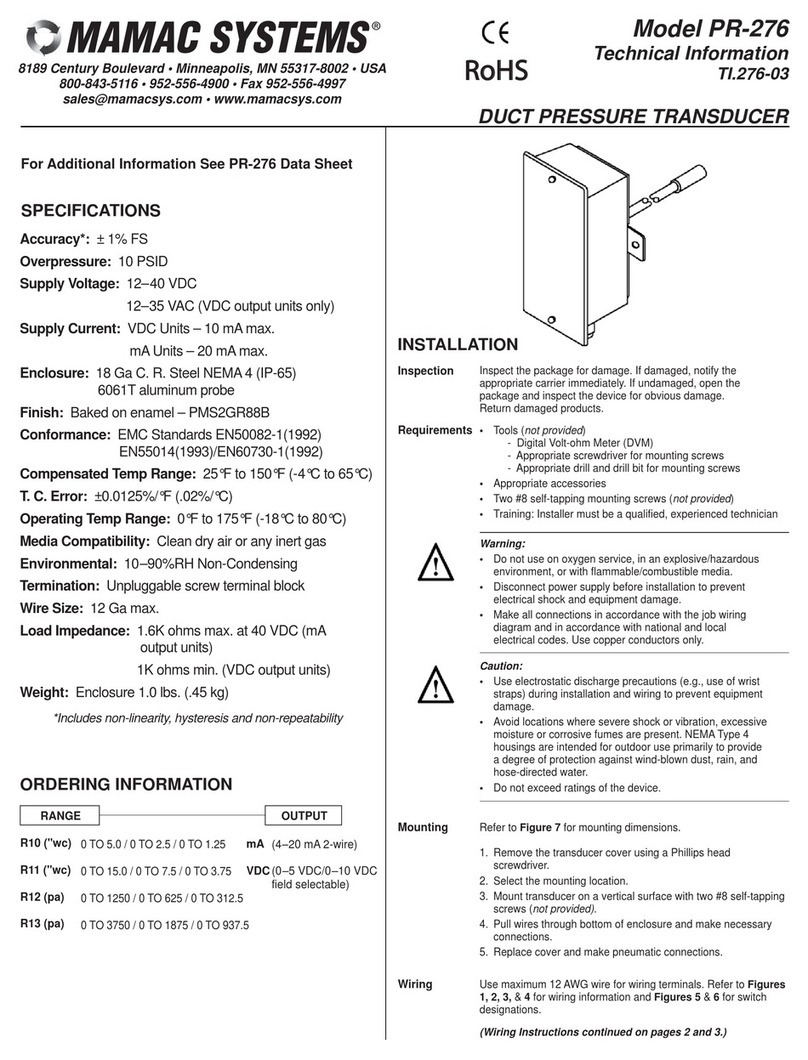
Accuracy*:±1%FS
MaximumSupplyPressure:40 psig
PressureDifferential:(SupplytoBranch)0.1psig
SupplyVoltage:18-28 VAC/VDC
SupplyCurrent: 150 mA
Enclosure:18 GaC.R.SteelChassis
Finish:Baked on enamel-PMS2GR88B
CompensatedTempRange:25ºF-150ºF(4ºC-65ºC)
Conformance:EMCStandardsEN50082-1(1992)
EN55014(1993)/EN60730-1(1992)
T.C.Error:±0.025%/ºF(.03%/ºC)
MediaCompatibility:Clean dryairoranyinertgas
PortConnection:1/4”ODpolytubing
Environmental:10-90%RH Non-Condensing
Termination:Screwterminalblock
WireSize:12 Gamax.
ImputImpedance:301 ohms(4-20 mA)
10Kohms(0-5/0-10 VDC)
Weight: 1.0lbs.(.45 kg)
*Includesnon-linearity,hysteresisand non-repeatability
FORADDITIONALINFORMATION
SEE EP-311/313 DATASHEET
SPECIFICATIONS
MANUAL
OVERRIDE
INSTALLATION
Inspection Inspectthe package fordamage.Ifdamaged,notif
the appropriatecarrierimmediately.If undamaged,
open the package and inspectthe devicefor
obviousdamage.Returndamaged products.
Requirements
•Tools(notprovided)
-DigitalVolt-ohmMeter(DVM)
-Appropriatescrewdriverformounting screws
-Appropriatedrill and drill bitformounting screws
•Appropriateaccessories
•Two#8 self-tapping mounting screws(not
provided)
•Training:Installermustbe aqualified,experienced
technician
Warning:
•Donotuseon oxygen service,inan
explosive/hazardousenvironment, orwith
flammable/combustiblemedia.
•Disconnectpowersupplybeforeinstallation to
preventelectricalshock and equipmentdamage.
•Makeall connectionsinaccordancewiththe jo
wiring diagram,and inaccordancewithnationa
and localelectricalcodes.Usecopperconductors
only.
Caution:
•Useelectrostaticdischarge precautions(e.g.,
useofwriststraps)during installation and wiring
topreventequipmentdamage.
•Donotexceed ratingsofthe device.
Mounting The EP-311/313 mustbe mounted inan uprightposition sothat
the portsarefacing upwardand the gauge can be easilyread.
1.Selectthe mounting location.
2.Mountthe transduceron averticalsurfacewiththree #8 self-
tapping screws(notprovided).
3.Pull wiresthrough the bottomofthe deviceand makenecessary
connections.
4.Makethe necessarypneumaticconnections.
Wiring Usemaximum12 AWGwireforwiring terminals.Useflexible1/4”
O.D.polytubing formainand branchpneumaticconnections.Refer
toFigure-1and Figure-2forwiring configurationsand Figure-4
through Figure-6forjumperdesignations.
Caution:
•Mainsupplypressuremustnotexceed 40 psig.
•Aminimumof6to10 feet(1.8to3.0m)oftubing shouldbe
between the unitand the actuator.
•For24 VACsupplyvoltage,ensurethatthe hotand neutralare
notreversed.If morethan one unitisbeing powered formthe
sametransformer,the hotand neutralshouldbe the samefor
eachunit.
Note:The gauge on the unitisforindication only.The unit’s
calibration ismoreaccuratethan the accuracy ofthe gauge.
!
311(without)315 (3-15 psig)
313(with)020 (0-20 psig)
RANGE
