Manitou JACK DROPPER POST User manual

JACK DROPPER POST SETUP GUIDE

3
JACK DROPPER POST SETUP GUIDE
Thank you for purchasing one of the most innovative hydraulic dropper posts on
the market - the Manitou Jack Dropper Seat Post. Your new seatpost is warranted
for a period of two years from the date of purchase. The warranty is limited to
the repair or replacement of the defective part and is the sole remedy of the
warranty. The warranty applies only to the original owner and is not transferrable.
Proof of purchase is required to validate warranty eligibility. The warranty does
not cover normal wear and tear, routine maintenance, improper installation or
improper use of the seatpost. Modication of the seatpost in any manor shall void
the warranty. shall not be responsible for incidental or individual costs incurred
by the warranty service provider that are not covered by this warranty. The user
assumes the risk of any personal injury or property damage, including damage
to the seatpost, and any other losses, if the seatpost is modied or improperly
used at any time. This warranty gives the consumer specic legal rights and
those rights vary from to This warranty does not aect the statutory rights of the
consumer.
INTRODUCTION
This is a high performance product. It will give you reliable service if installed
properly and regularly maintained by an authorized service center.
Read through these instructions fully and follow them carefully before installing
and/or using your new seatpost. Any questions about the servicing of this fork or
the manual itself should be directed to Hayes Customer Support at:
Hayes
Bicycle
USA
5800 W Donges Bay Road Mequon WI 53092
Phone: 888.686.3472
Email: techsupport@hayesbicycle.com
Hayes
Bicycle
Europe
Dirnismaning 20 a 85748 Garching (b. Munich) Germany
Phone: +49 89 203237450
Email: techsupportEU@hayesbicycle.com
Hayes
Bicycle
Asia
16F, No. 37, Sec. 3 Mincyuan E. Rd. Zhongshan District
Taipei City 10476 Taiwan ROC
Phone: 886-2-2518-1108
WARNING
! !
5800 W Donges Bay Rd
Mequon, WI 53092
manitoumtb.com
888.686.3472
Support: manitoumtb.com/support
MANITOU
For full warranty information please
visit hayesbicycle.com/warranty
WARRANTY

4 5
JACK DROPPER POST SETUP GUIDE JACK DROPPER POST SETUP GUIDE
table of contents
SECTION PAGE NUMBER
Before Installing the Seatpost 6
Installation 7
Usage 16
Service 20
FAQ 22
Troubleshooting 24
Exploded View 25
Your Jack Dropper Seatpost must be regularly maintained by a qualied service
technician. If you need assistance locating a qualied service technician, more
information can be found at www.manitoumtb.com. Do not disassemble your
seatpost by yourself Disassembly could cause damage and severe personally
injury as some of the contents are under pressure. Alway wear suitable safety
gloves and safety glasses, when working on your seatpost!
WARNING
! !
Please read the following instructions carefully and install your Jack Dropper
Seatpost according to the steps detailed below. Your Jack Dropper Seatpost is
a precision piece of cycling equipment that requires a specic understanding of
bicycle maintenance and assembly to install. If you are not certain that you have
the appropriate skills or tools to properly install or service this product, please
contact your local bicycle dealer or service provider for assistance.
Jack Dropper Seatpost models use internal cable routing and are designed to be
compatible with bicycle frames that feature such cable routing.
DO NOT DRILL OR MODIFY YOUR FRAME IN ANY WAY. Doing so will void
the Warranty of and in most cases void the warranty of your bicycle.
Modication of your frame in any way may result in frame failure which
could result in injury or death.
If you are unsue whether your Jack Dropper Seatpost is compatible with your
frame, contact your bicycle frame manufacturer or Manitou directly.
Thank you for choosing a Manitou dropper seatpost.
To ensure maximum and enduring performance with your Jack or Jack SL, please
read and follow this manual carefully and keep it for future reference.
If you purchased your seatpost separately, you will nd instructions on how to
install it. Please note that your Jack requires regular maintenance and care - see
the corresponding chapter in this manual.
You can also nd many important and useful tips in our service app or on
www.manitoumtb.com.
Happy trails
Your Manitou team
NOTICE
6 7
JACK DROPPER POST SETUP GUIDE JACK DROPPER POST SETUP GUIDE
before installing the seatpost installation
Please be sure that your new Jack Dropper Seatpost will t in your frame. All
Jack Dropper Seatpost models are designed to t either 30.9mm or 31.6mm seat
tube inner diameters in frames, originally designed for internal cable routing.
Improper t may cause slippage, faulty performance, injury or death and may
result in void of warranty.
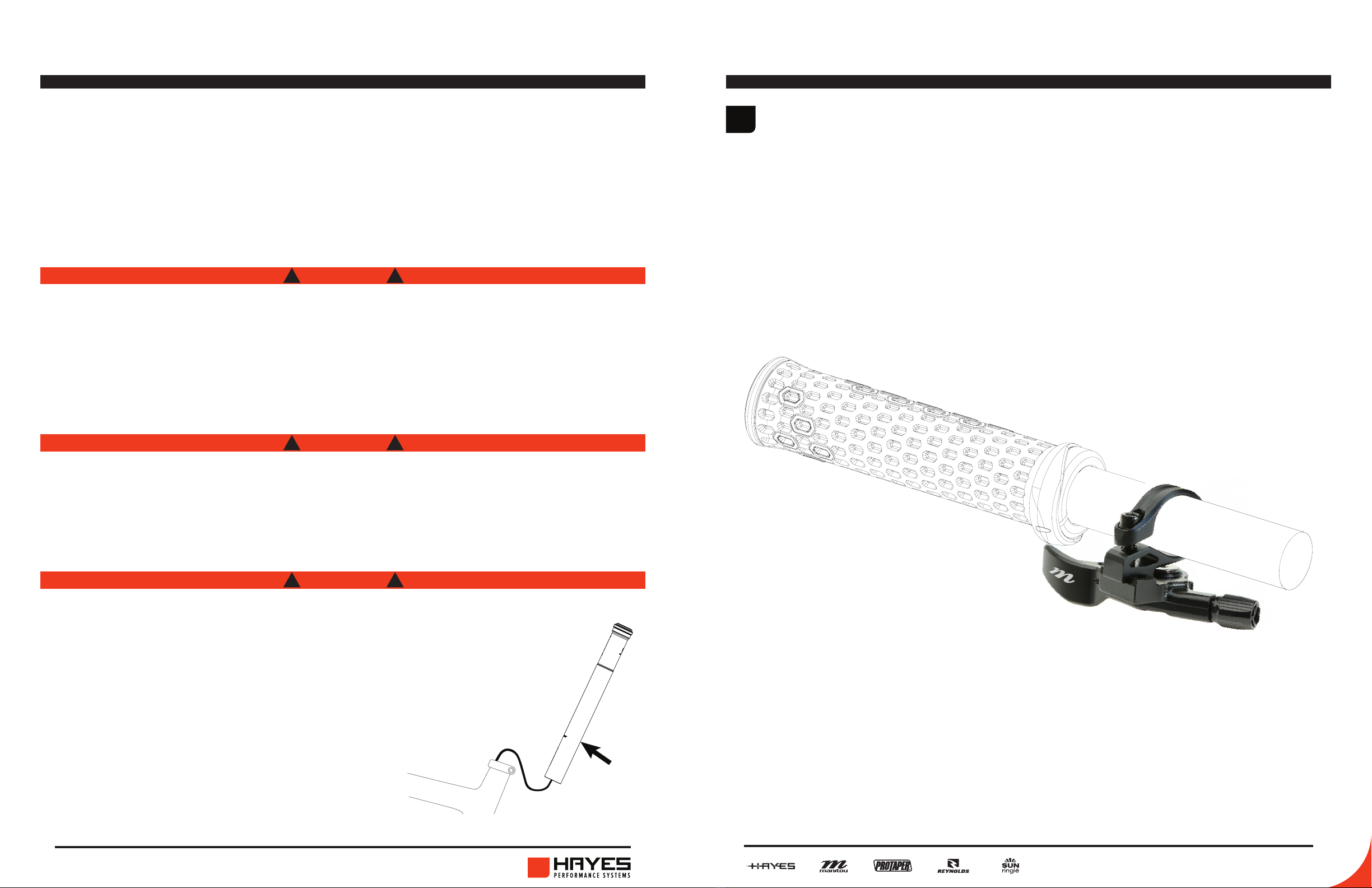
Manitou Underbar Lever remote can be installed with a stand alone clamp on
your handlebar, or an adapter directly on your brake using the Hayes Peacemaker
clamp. Use a maximum torque of 1.5 Nm on the pinch bolt on the clamp. Manitou
Underbar Lever remotes can only be installed on the left side of the handlebar.
Apply a heavy suitable grease on
the lower tube of the post to avoid
galvanic corrosion inside the frame use
friction paste instad of grease only if
the post can not be clamped properly.
Avoid using any paste,that could be
aggressive towards frame and/or post.
Manitou DOES NOT recommend modication or alteration of your frame in any
way. Doing so may void your frame or bicycle’s warranty and may result in frame
failure which could lead to injury or death.
WARNING
! !
Make sure that your seat tube is clean and free of debris and that the inside of
your seat tube is smooth and free of any object that may score the seatpost!
WARNING
! !
WARNING
! !
1INSTALLING MANITOU UNDERBAR REMOTE LEVER
grease

8 9
JACK DROPPER POST SETUP GUIDE JACK DROPPER POST SETUP GUIDE
installation installation
Route the housing through your bicycle frame per your bicycle frame
manufacturer‘s specications.
To determine the correct housing length, place the housing into the tension
adjuster of your remote, and make sure your handlebar can turn a minimum of
90° without stretching the housing.
Do not permanently ax your housing in place. You will need it free to move in a
later step.
Mark the position of your cable housing at the seat clamp, as it protrudes from
the seat tube.
Pull the cable housing out of the seat tube and make another mark 90 mm
downwards. This will be your nal housing length for minimum insertion.
If you insert your post deeper you can cut the housing shorter accordingly to
avoid excessive slack of your housing.
2 2
DETERMINING CABLE HOUSE LENGTH DETERMINING CABLE HOUSE LENGTH (CONTINUED)
9
INSTALLATION
STEP 2: DETERMINING HOUSING LENGTH
Route the housing through your bicycle frame per your
bicycle frame manufacturer‘s specications.
To determine the correct housing length, place the housing
into the tension adjuster of your remote, and make sure your
handlebar can turn a minimum of 90° without stretching the
housing.
Do not permanently ax your housing in place. You will need
it free to move in a later step.
remote lever
cable housing
10
INSTALLATION
STEP 2: DETERMINING CABLE HOUSE LENGTH
Mark the position of your cable housing at the seat clamp, as it
protrudes from the seat tube.
Pull the cable housing out of the seat tube and make another
mark 90 mm downwards. This will be your nal housing length
for minimum insertion.
If you insert your post deeper you can cut the housing shorter
accordingly to avoid excessive slack of your housing.
mark here
cut here
cable housing
90mm
seat clamp Cut the housing to
length with proper cable
cutters.
cable housing
seat clamp
1.
2.
10 11
JACK DROPPER POST SETUP GUIDE JACK DROPPER POST SETUP GUIDE
installation installation
The Manitou Jack dropper post uses a specic lightweight dropper post cable and
housing. The cable head replaced the cable end used by other brands to improve
setup and function. If the user desires a standard cable and cable end can be
used.
1. Push the ferrules onto both ends of the cable housing as far as possible.
2. Guide the inner cable through the cable housing from the seat tube towards
the remote lever with the Manitou dropper cable head terminating on the post
side.
3. Insert the inner cable through the remote lever and using the guide on the
bottom side of the post allow 17mm of cable to protrude out of the housing.
Tighten the pinch bolt on the lever too 2 Nm.
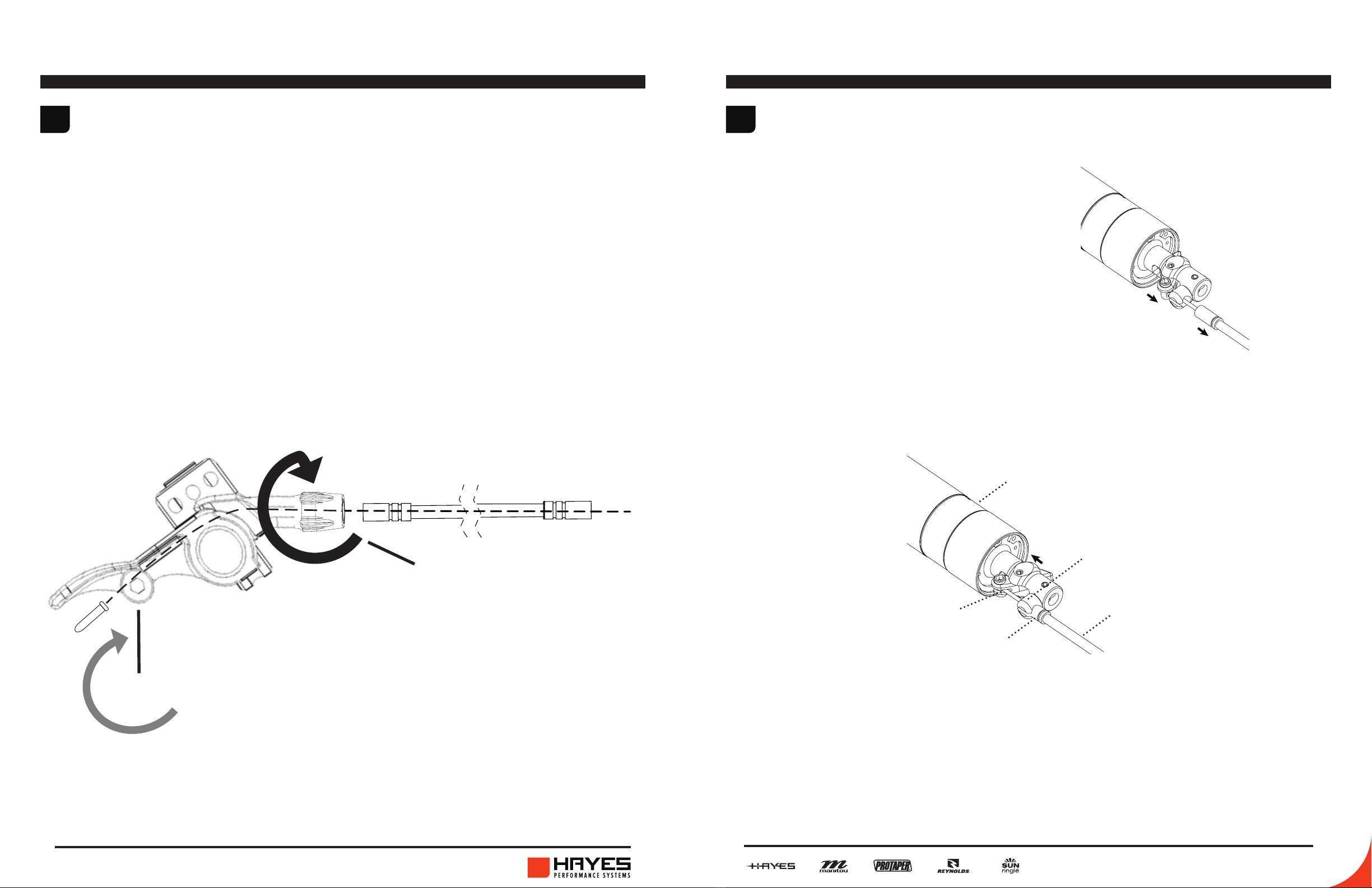
1. Insert the cable head end into the
actuation lever. Gently pull on the outer
housing and move the lever down
to pass the cable end stop with the
ferrule.
2. Guide the inner cable through the slotted cable end stop and push the ferrule f
irmly into the cable end stop by hand.
3. Adjust the tension with the cable tensioner on the lever, so there is no play in
the cable. If the tension is too high, it will permanently activate the post. A low
tension will cause cable play, and the post will not reach its full speed.
4. Cut the inner cable and secure it with an end cap.
3 4
PREPARING INNER CABLE CONNECTING CABLE TO SEATPOST
INSTALLATION
STEP 4: CONNECTING CABLE TO SEATPOST
1. Insert the barrel nut end into the
actuation lever.
2. Gently pull on the outer housing and
move the lever down to pass the cable
end stop with the ferrule.
3. Guide the inner cable through the slotted
cable end stop and push the ferrule
rmly into the cable end stop by hand.
mast
slotted cable stop
cable housing
cable head
12 ferrule
INSTALLATION
STEP 4: CONNECTING CABLE TO SEATPOST
1. Insert the barrel nut end into the
actuation lever.
2. Gently pull on the outer housing and
move the lever down to pass the cable
end stop with the ferrule.
3. Guide the inner cable through the slotted
cable end stop and push the ferrule
rmly into the cable end stop by hand.
mast
slotted cable stop
cable housing
cable head
12
ferrule
adjust cable
tension
2Nm

12 13
JACK DROPPER POST SETUP GUIDE JACK DROPPER POST SETUP GUIDE
installation installation
There is only one position for seatpost direction, saddle and saddle clamp
orientation.
Insert the seatpost into your seat tube. When inserting or extending, make sure
you do not pull too hard on the outer housing, as doing so may pull the ferrule
out of the cable stop.
5 5
INSERTING SEATPOST INSERTING SEATPOST (CONTINUTED)
13
INSTALLATION
STEP 5: SEATPOST ORIENTATION
There is only one position for seatpost direction, saddle and
saddle clamp orientation.
rear of bike front of bike
Insert slowly and carefully! When inserting, make sure there are no such things
as pivot points, bent tubes, etc inside your seattube that can interfere with the
seatpost.
WARNING
! !
You should always use a good quality grease on contacting faces between
seatpost and seattube in order to prevent corrosion. Use friction paste only
if proper clamping is impossible with greased components. Contact us before
applying friction paste.
WARNING
! !
Make sure your post does not slip inside the seat tube when sitting on it, before
going out for a real ride.
WARNING
! !
Over-tightening your frame‘s seat clamp might lead to a stuck post and/or
increased wear. Use only as much torque as you need to keep the post in place
during normal riding. It is appropriate for the post to rotate or slip under higher
input forces to prevent overload. Never exceed 5 Nm of torque!
WARNING
! !
14 15
JACK DROPPER POST SETUP GUIDE JACK DROPPER POST SETUP GUIDE
installation
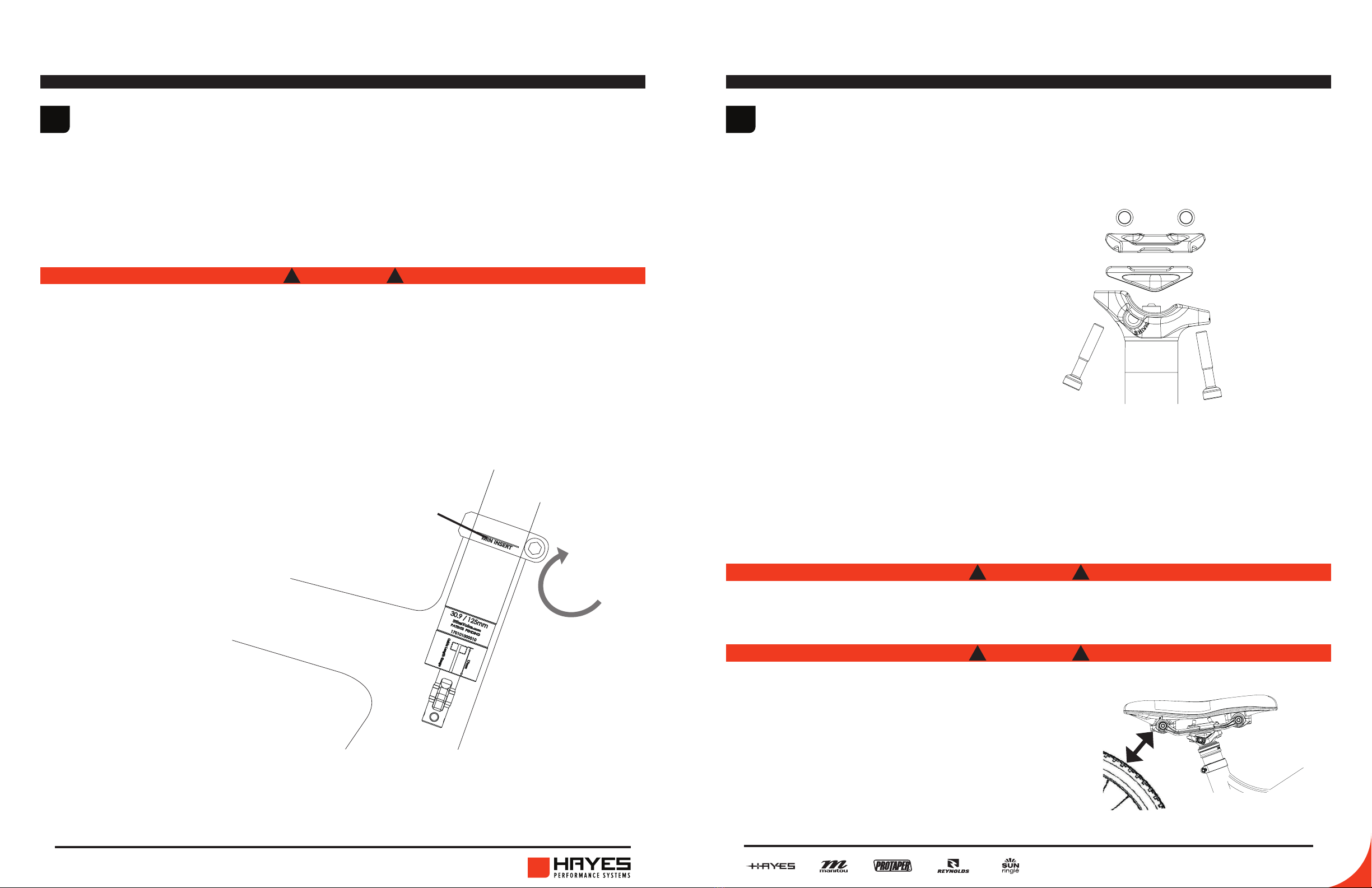
All seatpost models must be inserted into the bicycle’s seat tube, so that the
minimum insert line is covered by the seat tube at all times or deeper.
5INSERTING SEATPOST (CONTINUTED)
Insucient seatpost insertion into the bicycle frame‘s seat tube could result in
damage to the seatpost and/or bicycle, causing loss of control, which could lead
to serious injury or death. In case your frame requires more minimum insertion
depth than the post, follow the frame specication.
WARNING
! !
5Nm
Sattelklemme
INSTALLATION
STEP 5: MINIMUM INSERTION DEPTH
All seatpost models must be inserted into the bicycle’s seat
tube, so that the minimum insert line is covered by the seat
tube at all times or deeper.
WARNING: Insucient seatpost insertion into the
bicycle frame‘s seat tube could result in damage to
the seatpost and/or bicycle, causing loss of control,
which could lead to serious injury or death.
In case your frame requires more minimum insertion
depth than the post, follow the frame specication.
MIN INSERT
SEAT CLAMP TORQUE:
Tighten your frame’s seat
collar to a maximum
torque of 5 Nm.
max.
5Nm
15
installation
Remove the saddle clamp bolts, barrel nuts, and upper and lower saddle clamps
with a T25 Torx wrench.
Adjust the saddle angle by tightening the two saddle clamp bolts. Tighten both
bolts evenly and alternately to the maximum torque specied on the seatpost.
Ensure that the shaft or thread of the bolts does not contact the post and cause
the bolts to bend.
Jack saddle clamp works with standard rails, oval rails and carbon rails.
To install the saddle, replace the two
saddle clamp bolts, barrel nuts, upper
and lower saddle clamps in the order
they were removed. Ensure that the
rails of your saddle rest in the channel
provided by the upper and lower saddle
clamps before tightening.
6SADDLE INSTALLATION
GREASE SHOULD NOT BE USED ON THE THREADED CONNECTIONS!
WARNING
! !
With seatpost fully dropped and rear
suspension fully compressed, make sure
there is sucient clearence between the
saddle and the tire
WARNING
! !
2Nm
17
INSTALLATION
STEP 7: SADDLE INSTALLATION
Remove the saddle clamp bolts, barrel nuts, and upper and lower
saddle clamps with a T25 Torx wrench (4 mm Allen key on older
models).
To install the saddle, replace the two
saddle clamp bolts, barrel nuts, upper
and lower saddle clamps in the order
they were removed. Ensure that the
rails of your saddle rest in the channel
provided by the upper and lower
saddle clamps before tightening.
Adjust the saddle angle by tightening the two saddle clamp
bolts. Tighten both bolts evenly and alternately to the
maximum torque specied on the seatpost. Ensure that
the shaft or thread of the bolts does not contact the post
and cause the bolts to bend.
REVIVE saddle clamp works with standard rails, oval rails
and carbon rails.
CAUTION: GREASE SHOULD NOT BE USED ON THE THREADED
CONNECTIONS!
CAUTION: With seatpost fully
dropped and rear suspension fully
compressed, make sure there
is sucient clearence between
the saddle and the tire.
36
barrel nut
upper saddle
clamp
lower saddle
clamp
saddle clamp
bolts
Torx T25
barrel nut
upper saddle
clamp
lower saddle
clamp
saddle clamp
bolts
Torx T25
16 17
JACK DROPPER POST SETUP GUIDE JACK DROPPER POST SETUP GUIDE
usage
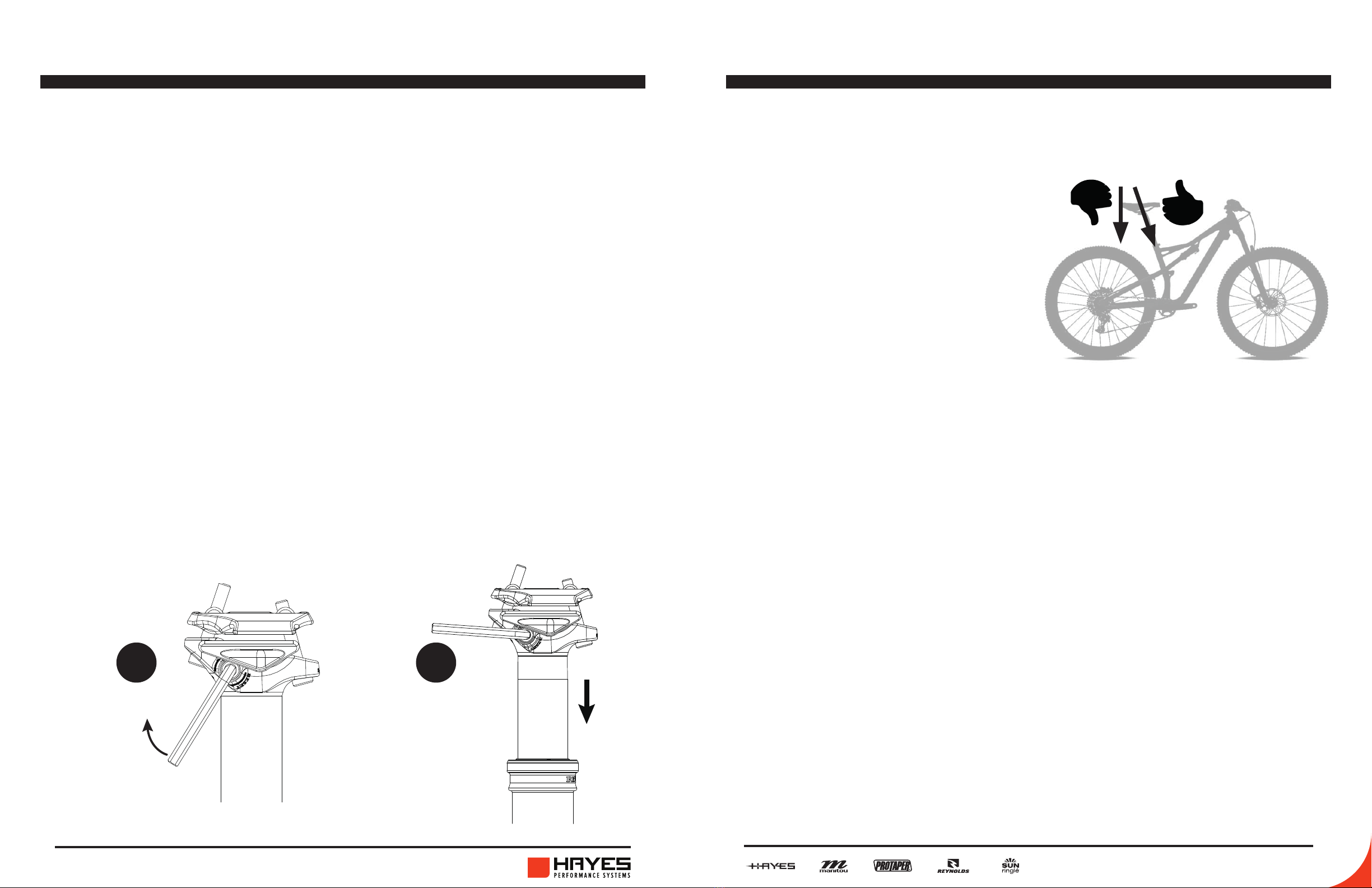
When you receive your post, it will have travelled a long way to reach you. Do a
hydraulic reset using the Jack’s patented reset feature after installing the post
1. Extend the post completely by pushing the remote.
2. Use the included reset lever or a 4 mm Allen key to turn the reset valve
clockwise until you feel a stop.
3. Drop the post by hand completely, while keeping the reset valve open.
4. Release the reset valve, remove hand from saddle.
5. To extend the post, push the remote.
After this procedure, the correct function should be restored completely. Reset,
if necessary, after a few minutes to give the oil a chance to settle down if it still
feels springy.
When your post begins to feel springy, use the reset function. „Springyness“
can be caused by storing your bike upside down or lying on its side. Whenever
possible, store or park your bike upright to avoid having to reset it.
BEFORE FIRST RIDE
18
USAGE
BEFORE FIRST RIDE
When you receive your post, it will have travelled a long way
to reach you. Do a hydraulic reset using the REVIVE‘s patented
reset feature after installing the post:
1. Extend the post completely by pushing the remote.
2. Use the included reset lever or a 4 mm Allen key to turn the
reset valve clockwise until you feel a stop.
3. Drop the post by hand completely, while keeping the reset
valve open.
4. Let go of the saddle once you have released the reset valve.
5. To extend the post, push the remote.
After this procedure, the correct function should be restored
completely. Reset, if necessary, after a few minutes to give the
oil a chance to settle down if it still feels springy.
When your post begins to feel springy, use the reset function.
„Springyness“ can be caused by storing your bike upside down
or lying on its side. Whenever possible, store or park your bike
upright to avoid having to reset it.
open
reset-valve
Allen key 4 mm
1st 2nd
drop post
while keeping
reset valve
open
usage
To raise the saddle, push the trigger with unweighted saddle. Once the desired
position is reached, release the trigger. You can set the saddle height innitely in
any position within the post’s travel range.
Your post might need to be manually broken loose if it hasn‘t been used or
adjusted for a long time, since the seals tend to stick to the contacting surfaces.
For this initial „break-away“ just push the remote and then gently push or pull the
saddle until the post starts moving.
TIP: Always store the bike with the dropper not fully extended. This will prevent
the remote from stiening up due to temperature changes (hydro-lock). Dropping
the post about 1/2“-1“ is plenty enough.
DROP AND EXTEND
The saddle can be dropped by
(1) Unweighting it
(2) Pushing the trigger
(3) Sitting on the saddle rmly
Ensure smooth action and reduce wear
on pins and bushings inside the post by
applying force only in the direction of the
seat tube axis.
19
USAGE
DROP AND EXTEND
The saddle can be dropped
by (1) unweighting it,
(2) pushing the trigger, and
(3) sitting on the saddle rmly.
Ensure smooth action and
reduce wear on pins and
bushings inside the post by
applying force only in the
direction of the seat tube
axis.
To raise the saddle, push the trigger with unweighted saddle.
Once the desired position is reached, release the trigger.
You can set the saddle height innitely in any position within
the post’s travel range.
Your post might need to be manually broken loose if it hasn‘t
been used or adjusted for a long time, since the seals tend to
stick to the contacting surfaces.
For this initial „break-away“ just push the remote and then
gently push or pull the saddle until the post starts moving.
TIPP: Always store the bike with the dropper not fully extended.
This will prevent the remote from stiening up due to temperature
changes (hydro-lock). Droppening the post about 1/2“-1“ is
plenty enough.

18 19
JACK DROPPER POST SETUP GUIDE JACK DROPPER POST SETUP GUIDE
usage
1. Reset the post and then fully extend to maximum length before adjusting air
pressure. Let the post rest for 30 seconds.
2. Remove the saddle clamps.
3. Move the reset lever to upward position using a 4 mm Allen key or the reset
lever.
ADJUSTING RETURN SPEED
Your Jack SL comes with a factory setting of 240~250 psi in air pressure. This
pressure will provide a good balance between return speed and lever force.
However, if you feel your return speed is too slow, you can make your post faster
by increasing air pressure up to a maximum of 290 psi.
Keep your post right side up and fully extended, when adjusting air pressure.
Never operate the air valve, while the post is laying horizontally or upside down
or you will cause suspension uid to leak out of the post under high pressure!
This can cause severe injuries!
WARNING
! !
CAUTION
Safety glasses and gloves must always be worn when adjusting the air pressure,
since the dropper post contains high pressures and suspension uid
20
USAGE
ADJUSTING RETURN SPEED
Your REVIVE comes with a factory setting of 240~250 psi in air
pressure. This pressure will provide a good balance between
return speed and lever force. However, if you feel your return
speed is too slow, you can make your post faster by increasing
air pressure up to a maximum of 290 psi.
CAUTION: Safety glasses and gloves must always
be worn when adjusting the air pressure, since
the dropper post contains high pressures
and suspension uid!
WARNING: Keep your post right side up and
fully extended, when adjusting air pressure.
Never operate the air valve, while the post is
laying horizontally or upside down or you will
cause suspension uid to leak out of the post
under high pressure! This can cause severe injuries!
1. Reset the post and then fully extend to maximum length
before adjusting air pressure. Let the post rest for 30 seconds.
2. Remove the saddle clamps.
3. Move the reset lever to upward position using a 4 mm Allen
key or the reset lever.
usage
ADJUSTING RETURN SPEED (CONTINUED)
4. Remove the valve cap from the valve housing. Do not lose this small plug since
it is essential for proper reset function.
5. Attach the air valve adapter and then attach the shock pump onto the adapter.
Make sure not to overtight the shock connection.
6. Pump the post to desired pressure. We do not recommend pressures lower
than 210 psi, since it can make the post become very slow. Maximum pressure is
290 psi. We recommend to use a high quality shock pump with a 2-step valve to
avoid air loss, when detaching the pump.
7. Remove pump and adapter from the post.
8. Clean your post from any excessive suspension uid.
9. Reinstall all previously removed parts in the order they were removed.
Instead of using the air adapter, you can also remove the reset axle and attach
the pump directly.
21
USAGE
ADJUSTING RETURN SPEED
4. Remove the valve cap from the valve housing.
Do not lose this small plug since it is essential for
proper reset function.
5. Attach the air valve adapter and then attach the shock
pump onto the adapter. Make sure not to overtight the
shock connection.
6.
Pump the post to desired pressure. We do not recommend
pressures lower than 210 psi, since it can make the post become
very slow. Maximum pressure is 290 psi. We recommend to
use a high quality shock pump with a 2-step valve to avoid air
loss, when detaching the pump.
7. Remove pump and adapter from the post.
8. Clean your post from any excessive suspension uid.
9. Reinstall all previously removed parts in the order they
were removed.
Instead of using the air adapter, you can also remove the reset
axle and attach the pump directly.
air valve
adapter
Allen key 1.5 mm Allen key 2 mm
OR
Allen key 4 mm
20 21
JACK DROPPER POST SETUP GUIDE JACK DROPPER POST SETUP GUIDE
SERVICE
MAINTENANCE
You can expect reliable service from this high-performance product if properly
installed and regularly maintained by an authorized Manitou service center or a
qualied service technician.
For assistance locating a qualied service technician, visit www.manitoumtb.com.
Besides routine maintenance, the operator must check the seatpost every time it
is used to ensure proper operation.
Your new seatpost is warranted for a period of two years from the date of
purchase. The warranty is expressly limited to the repair or replacement of the
defective part and is the sole remedy of the warranty.
Do not disassemble your seatpost by yourself unless you are a skilled and
authorized technician! Failure to follow these warnings and instructions will
immediately void your warranty!
WARNING
! !
CAUTION
When working on the seatpost, gloves and safety glasses must always be worn!
As some of the components are under high pressure, disassembling the seatpost
may cause damage and severe personal injury.
SERVICE INTERVALS
BEFORE EVERY RIDE
• CHECK SADDLE CLAMPS FOR PROPER FIT
• INSPECT THE POST FOR DAMAGE
• CHECK FUNCTION
AFTER EVERY RIDE
• GENTLY WIPE OFF DIRT & WATER (NO POWER WASH!)
• MAKE SURE NO WATER ENTERS THE FRAME DURING WASHING (HUMIDITY CAN
CAUSE CORROSION)
• STORE BIKE IN A DRY PLACE
MINIMUM EVERY 12
MONTHS OR AFTER 100
HOURS OF OPERATION*
• LOWER TUBE SERVICE**
UPON NEED • FULL CARTRIDGE SERVICE**
MAINTENANCE
SERVICE
*whichever comes rst
** Complete maintenance plan, instructions and video tutorials can be
found on www.bikeyoke.com!
Before longer periods of non-use (>1 month), be sure to carry out a service on
the lower tube unit to prevent corrosion damage due to humidity.
Depending on the amount of use and riding conditions, a shorter maintenance
interval may be necessary in order to ensure a smooth function of your Manitou
seatpost!

22 23
JACK DROPPER POST SETUP GUIDE JACK DROPPER POST SETUP GUIDE
faq
IS THERE A WEIGHT LIMIT ON THE JACK DROPPER POST?
Our Jack / Jack SL has a maximum rider weight of 115kg (253lbs).
CAN I USE OTHER REMOTES THAN MANITOU?
We support all commonly available cable dropper remotes. To provide full return
speed and smooth drop feel, your remote should have a least 10 mm of cable pull
for Jack and at least 5 mm of cable pull for Jack SL.
CAN I MOUNT SADDLES THAT HAVE CARBON RAILS AND/OR HIGH-
OVAL RAILS TO MY POST?
Our Jack droppers are compatible with standard 7x7 mm and oval rails 7x9 or
7x10 mm made from carbon or alloy.
CAN I CLAMP MY MANITOU SEATPOST IN THE ASSEMBLY STAND?
We recommend to clamp only the lower tube unit with care.
CAN I GET SPARE PARTS FOR MY JACK?
We have all important spare parts available in our online shop, at our distributors
and listed Manitou dealers. Other parts are available on demand.
IS THERE ANYTHING I NEED TO CONSIDER WHEN LOWERING MY POST?
Before pushing the remote lever, slightly unweight your saddle. Always apply the
drop force along the seat tube direction!
faq
MY POST SLIGHTLY COMPRESSES UNDER LOAD. IS THAT NORMAL?
A small amount of compression movement is absolutely normal and harmless,
and can be up to 1-2 mm.
WHAT DO I HAVE TO CONSIDER WHEN INSTALLING THE SADDLE?
Alternately tighten the clamping bolts to the torque specied on the dropper post.
IMPORTANT: Do not grease the saddle clamp bolts.
CAN I LIFT MY BIKE ON THE SADDLE?
It is acceptable for Manitou droppers to carefully lift the bike on the saddle.
IS IT OKAY TO USE T-BAR LIFTS WITH MY MANITOU SEATPOST?
Manitou generally advises against using t-bar lifts. In addition to the obvious risk
of scratching the post‘s coating, the multitude of lift variants result in incalculable
loads on the post, which can lead to possible late eects. Any use of our
seatposts on t-bar lifts is expressly at the user‘s own risk and voids the warranty.
FOR MORE ANSWERS AND QUESTIONS CHECK OUT OUR WEBSITE.

24 25
JACK DROPPER POST SETUP GUIDE JACK DROPPER POST SETUP GUIDE
ISSUE POTENTIAL CAUSE SOLUTION
Remote lever
does not return
Actuator lever (#48) or plunger (#32)
are seized
Properly clean and grease actuator lever and
plunger (use thick grease, not suspension grease)
Seized inner cable due to corrosion Replace inner and outer cable
Remote lever is
hard to push
Riding in low temps, then going back
inside will let oil expand and cause
extensive pressure inside inner chamber
Use 4mm Allen Key to engage reset function ->
pressure will equalize. Advise to drop the post
before storing the bike after coming back from
rides in cold temps to avoid this happening again
Oil betwen piston shaft (#29) and push
rod (#30) -> defective seal (#53)? Full rebuild and replacement of defective seal
Sticky or ow
movement
Water or dirt or corrosion inside lower
tube or lack of grease Lower tube service
Foam ring (#45) clogs breathing holes at
bottom of post
Clean or replace foam ring, if neccessary perform
lower tube service
Pressure is too low Reset pressure to 260 psi
Cable tension too low Increase cable tension
Seat collar torque too high Check seat collar (max 5Nm)
Post clamped too close to collar Move post out of seattube by 2mm
Outside temperature too low Post should normally work ne until as low as -10°
C (with original oil)
Air leakage Schrader valve or O-rings (#17 or #18)
not tightened or defective
Tighten or replace schrader valve and/or full
cartrideg rebuild with replacement of defective parts
Oil leakage Defective O-ring #53 or defective lower
seal head assembly Full rebuild with replacement of defective parts
Post sinks owly
under load
Defective O-rings #16, #21, #24 or #27 Full rebuild with replacement of defective parts
Cable tension too high Reduce cable tension
Outer housing endcap is diocated (after
post adjustment in frame) Relocate the outer housing endcap in ist seat
Post owly
extends by
itself
Defective O-rings #16, #21, #24 or #27 Full rebuild with replacement of defective parts
Cable tension too high Reduce cable tension
Outer housing endcap is diocated (after
post adjustment in frame) Relocate the outer housing endcap
Post requires
frequent resets
Post is early version without microvalve
(#54)
This is normal, if the post is stored and/or actuated
upside down Upgrading with new inner tube (#22)
and microvalve will make the post less prone to air
ingestion
Reset lever
does not return
Reset axle (#8) is seized Make sure set screw (#5) is not clamping the axle,
remove, clean and grease reset axle
Pressure is too low Set pressure to 260 psi
TROUBLESHOOTING EXPLODED VIEW
33
open with heat
46
19
27
5
Torque 4.5Nm
1
51
23
22
39
37
6
53
11
10
21
3
8
52
54
42
26
thread-lock strong, open with heat
55
12
20
13
29
torque 6Nm
44
40
45
50
49
41
4
7
57
36
43
48
34 7
32
24
BikeYoke REVIVE
47
17
30
25
upwards
38
28
lip must face
18
31
2
14
16
9
15
35
thread-lock medium
NOTE:
running change:
#41 + #42 = old
#57 = new
torque 4Nm
POS part name qty.
1barrel nut M5 2
2REVIVE upper saddle clamp 1
3REVIVE lower saddle clamp 1
4saddle clamp bolt M5x30 2
5set screw M3x0.5x3 1
6o-ring 5x1 1
7set screw M4x0.7x5 2
8REVIVE lever axle 1
9o-ring 6x1 1
10 REVIVE lever 1
11 REVIVE upper tube 1
12 valve plug 1
13 o-ring 3.5x1 1
14 valve core 1
15 REVIVE valve 1
16 o-ring 2x1.5 1
17 o-ring 13x2/11.5x2 1
18 o-ring 8x1.5 1
19 REVIVE seal head 1
20 spring pin 3x12 1
21 o-ring 8x2 1
22 inner tube 1
23 o-ring 7x2.5 1
24 backup-ring 1
25 main piston 1
26 valve spring 1
27 o-ring 2x1.5 NBR90 1
28 main valve 1
29 piston shaft 1
30 push rod 1
31 o-ring 4x1 1
32 shaft cap 1
33 o-ring 17x2 1
34 shaft bushing 1
35 lower seal head 1
36 u-cup 1
37 wiper /spring loaded wiper 1
38 upper stanchion bushing 1
39 lower tube 1
40 guiding pin 6
41 lower stanchion bushing 1
42 lower stanchion bushing washer 1
43 lower sealhead circlip 1
44 o-ring 18.64x3.53 1
45 foam cover 1
46 o-ring 24x2 1
POS part name qty.
47 actuator housing 1
48 actuator lever 1
49 cable stop 1
50 actuator circlip 1
51 spring pin 3x10 2
52 barrel nut 1
53 o-ring 2.5x1.5 1
54 Microvalve 1
55 reset lever 1
56 air adapter (not pictured) 1
57 lower bushing (IGUS) 1
Cartridge fluid volumes:
125mm = 35ml
160mm = 41.5ml
185mm = 46ml
213mm = 60ml
BikeYoke recommends 96% Mobil DTE 10 Excel 15 with 4% r.s.p. No Stick Slip.
Other suspension oils with similar viscosity will work, but may differ in performance.
Recommended grease:
r.s.p. Slick Kick
r.s.p. Soft grease
SRAM Butter
KS Post Paste
Buzzy's Slick Honey
Don´t use spray-on lubricants!
33
open with heat
46
19
27
5
Torque 4.5Nm
1
51
23
22
39
37
6
53
11
10
21
3
8
52
54
42
26
thread-lock strong, open with heat
55
12
20
13
29
torque 6Nm
44
40
45
50
49
41
4
7
57
36
43
48
34 7
32
24
47
17
30
25
upwards
38
28
lip must face
18
31
2
14
16
9
15
35
thread-lock mediu m
torque 4Nm

16F, No. 37, Sec. 3
Mincyuan E. Rd.
Zhongshan District
5800 W. Donges Bay Rd.
Mequon, WI 53092
Dirnismaning 20 a
85748 Garching (b. Munich)
Germany
16F, No. 37, Sec. 3
Mincyuan E. Rd.
Zhongshan District
GLOBAL HEADQUARTERS &
HAYES BICYCLE GROUP USA
HAYES BICYCLE GROUP EU
HAYES BICYCLE GROUP ASIA
facebook.com/ManitouMTB
instagram.com/ManitouMTB
#ScienceofSmooth
Table of contents
Other Manitou Bicycle Accessories manuals

Manitou
Manitou DORADO User manual

Manitou
Manitou 2001 MARS User manual

Manitou
Manitou Circus Expert User manual

Manitou
Manitou MARA PIGGYBACK User manual

Manitou
Manitou XVERT R User manual

Manitou
Manitou DORADO EXPERT 37MM User manual

Manitou
Manitou Mara Pro User manual

Manitou
Manitou Axel Super 2004 User manual

Manitou
Manitou DORADO DH User manual

Manitou
Manitou SIX User manual


Popular Bicycle Accessories manuals by other brands


Specialized
Specialized Elite CylcoComputer user manual

Sigma
Sigma BC 16.16 manual

Playcore
Playcore Dero Setbacks installation instructions

VDO Cyclecomputing
VDO Cyclecomputing x3dw instruction manual

Cateye
Cateye RAPID X2 manual

buratti meccanica
buratti meccanica Clorofilla Trail Use and maintenance manual


