Manitou DORADO DH User manual

AMERICAN MADE
MANITOU SUSPENSION
CONGRATULATIONS ON CHOOSING THE LATEST IN SUSPENSION
TECHNOLOGY AVAILABLE, A 2003 MANITOU DORADO FORK BUILT
IN THE USA. This DORADO fork is fully assembled and is ready to
be installed onto your bicycle. It comes equipped with a 1 1/8-inch
threadless steerer tube, AND is only available with a disc brake ver-
sion.
2003 DORADO FORK LINE
DORADO DH . . . . . . . . . . 180 MM TRAVEL / COIL SPRING /
TPC+ DAMPING
DORADO SC. . . . . . . . . . . 130 MM TRAVEL / COIL SPRING /
TPC+ DAMPING
You can also download this manual at www.answerproducts.com.
BICYCLING IS A HAZARDOUS
ACTIVITY THAT REQUIRES THAT
THE RIDER STAY IN CONTROL OF HIS OR HER BICYCLE AT ALL
TIMES. READING THIS MANUAL ENTIRELY AND PROPERLY MAIN-
TAINING YOUR BICYCLE AND SUSPENSION FORK WILL REDUCE THE
POSSIBILITY OF INJURY OR POSSIBLE DEATH. PRIOR TO RIDING
YOUR BICYCLE, YOU SHOULD INSPECT YOUR SUSPENSION FORK TO
ENSURE THAT NO DAMAGE HAS OCCURRED DURING THE COURSE OF
RIDING. DO NOT RIDE YOUR BICYCLE IF THE FORK SHOWS ANY
SIGNS OF BENDING, CRACKING, LEAKING, OR IF IT IS MISSING ANY
OF THE ORIGINALLY SUPPLIED COMPONENTS. ANY FALL FROM
YOUR BICYCLE CAN RESULT IN SERIOUS INJURY OR EVEN DEATH.
FOLLOWING THESE INSTRUCTIONS CAN HELP YOU REDUCE THE RISK
OF BEING INJURED.
IF YOU ARE A MODERATE OR AGGRESSIVE OFF-ROAD RIDER,
OR RIDE AT LEAST THREE TIMES A WEEK OVER ROUGH TERRAIN,
ANSWER RECOMMENDS RETURNING YOUR SUSPENSION FORK
EVERY 2 YEARS FOR A THOROUGH INSPECTION AND UPDATE. TAKE
YOUR FORK TO A MANITOU AUTHORIZED DEALER WHO CAN
ARRANGE FOR SHIPMENT TO ANSWER PRODUCTS, OR YOU MAY
CALL ANSWER AT (661) 257-4411 TO HAVE YOUR FORK
SHIPPED DIRECTLY.
IMPORTANT: The DORADO fork is an off-road fork, and as
such, does not come with proper reflectors for on-road use.
CONSUMER SAFETY INFORMATION
1. Never remove or have the steerer tube or legs (SC version only)
removed from the crown. The steerer tube and legs are press fit
at the factory. Pressing the steerer tube or legs out will perma-
nently damage the crown beyond repair and render it unsafe for
any continued use.
2. Never attempt to thread a threadless steerer tube. Cutting
threads will weaken the steerer tube and cause an unsafe condi-
tion. The only safe thing to do is to obtain the proper
crown/steerer from your dealer.
3. Any other alteration or modification to your fork should be con-
sidered unsafe. Contact Answer Warranty prior to modifying
your fork in any way for safety information.
4. Do not use the DORADO fork if any parts are broken, bent,
cracked, or you suspect may be damaged. Contact your dealer
or Answer Warranty at (661) 257-4411 if you have any ques-
tions concerning the integrity or condition of your fork.
5. Answer Products recommends that you inspect your fork before
every ride for wear and damage. Inspect the crown, inner legs,
outer legs, and dropout areas for cracks or damage.
WARRANTY INFORMATION
Any Answer Products fork found by the factory to be defective in
materials and/or workmanship within one year from the date of pur-
chase (or two years in EU countries) will be repaired or replaced at
the option of the manufacturer, free of charge, when received at the
factory with proof of purchase, freight prepaid. This warranty does
not cover breakage, bending, or damage that may result from crash-
es or falls. This warranty does not cover any fork that has been sub-
ject to misuse or whose serial number has been altered, defaced or
removed. This warranty does not cover paint damage. Any modifica-
tions made by the user will render the warranty null and void. This
warranty is expressly in lieu of all other warranties, and any implied
are limited in duration to the same duration as the expressed warran-
ty herein. Answer Products shall not be liable for any incidental or
consequential damages.
If for any reason warranty work is necessary, return the fork to the
place of purchase. At that time, instructions for repair, return, or
replacement shall be given. Customers in countries other than USA
should contact their dealer or local distributor.
INSTALLATION AND SETUP
INSTRUCTIONS
Ensure that the proper top crown has been delivered on your DORA-
DO first. The steerer tube may need to be cut to length to fit your
bicycle head tube. If you are not familiar with this procedure, or do
not have the proper tools to cut the steerer tube, it is recommended
that you seek a dealer with a qualified bicycle mechanic to perform
installation.
THE STEERER TUBE AND LEGS (SC VERSION)
ARE A ONE TIME PRECISION PRESS FIT AT THE
FACTORY AND CANNOT BE REMOVED FROM THE CROWN. REPLACE-
MENT OF THE ENTIRE CROWN/STEERER ASSEMBLY MUST BE DONE
TO CHANGE STEERER TUBE LENGTHS OR DIAMETERS. REMOVING
AND REPLACING THE STEERER TUBE OR LEGS WILL RESULT IN AN
UNSAFE CONDITION AND SHOULD NEVER BE DONE.
FORK INSTALLATION
1. Remove the old fork from your bicycle.
2. Measure and cut the steerer tube to fit your bicycle head tube.
You generally will want to leave about 10–20 mm excess length
for the DH version.
3. Remove the headset crown race from the old fork and press
onto the DORADO steerer until the race is seated over the
crown.
4. Clean and grease the headset bearings and races.
5. Install the lower bearings (if applicable) on fork crown race.
6. Insert the steerer tube into the head tube of the frame.
7. Install the upper bearings, small spacer ring, and then the top
crown (for DH model).
8. Install the stem cap and bolt. Tighten the bolt to headset manu-
facturer’s specifications.
9. Install the handlebars to the desired height and torque stem
bolts to manufacturer’s specifications. On the DH model, torque
the 5 mm stem clamping system bolts to 60–75 in.-lbs. (7.3–8.5
Nm).
10. Install the brakes and adjust per the manufacturer’s instructions.
11. Install the small side of the hex lock through-axle through the
large opening and wheel. Tighten down the hex lock end bolt
until it is snug. Then tighten the dropout pinch bolts to 40–60
in.-lbs. (4.5–6.8 Nm).

UPPER TRIPLE CLAMP SIZING – DORADO DH
To fit a variety of bike head tube sizes, there are two distinct upper
triple clamps. The flat upper triple clamp is the small size and fits
head tubes between 130 mm and 160 mm in length. The drop upper
triple clamp is the large size and fits head tubes between 155 mm
and 185 mm in length. Both clamps must fully engage the aluminum
bulges on the outer tubes without extending beyond the small taper
line with the upper and lower clamps. All triple clamp bolts must be
torqued to 60–75 in.-lbs. (7.3–8.5 Nm).
HEX AXLE INSTALLATION
The hex axle used on DORADO forks is unique in that it allows
the legs to be locked together once the pinch bolts have been tight-
ened. To install the hex axle, simply slip the axle into the dropout,
small axle hex side first into the large dropout hex. Thread in the set
bolt into the small hex side and snug slightly. Push the fork up and
down a few times to center the axle and hub and then tighten all
pinch bolts to 40–60 in.-lbs. (4.5–6.8 Nm).
ATTACHMENT OF THE BRAKE CABLE
Failure to properly route and securely attach the brake cable to the
fork can cause serious injury or death. Included with the fork is a
small black cable guide that can be attached to the fork guard
depending on how you attach the cable. The best method we’ve
found is to attach the cable so that it runs down the outside of the
left fork leg. Just make sure that you do not attach the cable to the
fork any other place than on the fork guard, as this will cause the
cable to bind and possibly crimp as the fork is compressed. The
cable should be routed through the guides located on the upper car-
bon tubes but should be free to slide.
HANDLEBAR INSTALLATION – DORADO DH
The DORADO DH comes equipped with an integrated handlebar
upper triple clamp system. This provides additional steering stiffness
as well as puts the handlebars straight every time. All handlebar
bolts should be torqued to 50–60 in.-lbs. (5.7–6.8 Nm). All triple
clamp bolts and steerer tube bolts should be torqued to 60–75 in.-
lbs. (7.3–8.5 Nm).
SPRING SETUP – MEASURING SAG
You’ll need a tape measure, a pencil and a piece of paper.
1. Measure the distance from the front axle’s centerline to the bot-
tom of the lower crown without anyone sitting on the bike and
write this distance down. (Remember the exact locations of the
two points because you’ll need to use them later.)
2. Have the rider sit on the bike and measure the distance between
the same two points as in step one. It’s important to be in the
normal riding position (weight centered) with your feet on the
pedals.
3. Subtract the second measurement from the first. The resulting
measurement is the static sag.
SAG MEASUREMENT CHART
FORK MODEL FORK TRAVEL SAG
DORADO SC 130 mm 25 to 32 mm
DORADO DH 180 mm 40 to 45 mm
RIDE KITS
Each DORADO fork comes with two medium rate springs installed. In
addition, one firm spring and one soft spring have also been pack-
aged with the fork. Using the recommended sag measurements list-
ed above, adjust the spring stack as necessary. If there is too much
sag, replace a single spring at a time with a firmer one; if too little
sag, replace with a softer one. If additional adjustments are required,
ride kits can be purchased from Answer under the following part
numbers:
MODEL DH MODEL SC
SPRING RATE PART NO. SPRING RATE PART NO.
Soft 85-4946 Soft 85-4534
Medium 85-4947 Medium 85-4538
Firm 85-4948 Firm 85-4539
Extra Firm 85-4949
DAMPING ADJUSTMENTS –
DORADO FORKS
With DORADO forks, since the fork features an upside-down design,
the damping system is also reversed. As a result, compression
damping adjustment is now located at the bottom of the right leg
and rebound damping is on top of the right leg.
COMPRESSION DAMPING ADJUSTMENT – TPC PLUS
For TPC Plus-equipped DORADO forks, a turn of the knob located on
the bottom of the right leg is all that is needed to adjust compression
damping. Turning the knob clockwise (as you are looking at the fork
from the bottom) increases compression damping, while turning it
counterclockwise decreases compression damping.
REBOUND DAMPING ADJUSTMENT – TPC PLUS
Rebound adjusters on DORADO forks are located on the top of the
right fork leg. Turning the knob clockwise (as you are looking from a
rider’s position) increases rebound damping, while turning it coun-
terclockwise decrease rebound damping.
BEFORE EACH RIDE
IMPORTANT: The DORADO should not be used if any parts
appear to be or are damaged. Contact your local dealer or
Answer Products for replacement parts.
IMPORTANT: Before every ride you should:
1. Ensure that the through-axle is properly adjusted and tight.
2. Wipe the inner legs and clean and check the entire fork for any
obvious damage.
3. Check the headset for proper adjustment.
4. Ensure that the front brake cable is properly routed and check
brake adjustment.
BREAK-IN
Your new fork is designed to break in during your first few rides
(about 20 hours total riding time). Prior to break-in, you may notice
your fork feels tight and slightly sticky. Following the break-in period,
your fork will feel much smoother and react to bumps much better
than when you first put it on your bike. After 20 hours, you may
want to recheck your compression and rebound to fine tune the fork
completely.

MAINTENANCE
IMPORTANT:
1. Use of dirt guards is recommended to keep your DORADO fork
performing at its optimum for extended service cycles and
maintaining maximum life of the fork.
2. Use of this fork without dirt guards will require frequent serv-
ice intervals to maintain performance and normal life of the
fork.
3. Warranty will be void if fork is found to show that dirt guards
were not in place and frequent service was not performed.
Your DORADO fork requires periodic maintenance, cleaning and
inspection performed by a qualified service technician. This is
because moisture and contamination may build up inside the fork
depending on the severity of riding conditions.
If you have any questions regarding your 2003 Manitou DORADO
suspension fork in the U.S., contact the Answer Customer Service
Department at (661) 257-4411. For information outside of the U.S.,
contact your authorized Manitou dealer or distributor. You can also
log on to www.answerproducts.com and download this manual or
see detailed instructions on how to service your suspension fork.
Thank you again for choosing a 2003 Manitou DORADO suspension
fork.
DEALER SERVICE ADDENDUM
INTRODUCTION When servicing the fork, take the time to
inspect all parts for excessive wear or damage. There are basically
three aspects of a fork that will require attention:
1. Lubrication of stanchions (inner legs) and bushing inspection
2. Spring stack
3. Damping system
LUBRICATION OF STANCHIONS (INNER LEGS) AND
BUSHING INSPECTION The outer leg bushings need to be serv-
iced approximately every 40 hours of riding (depending on conditions
– extreme conditions may require a more frequent service schedule).
The method used to determine if your fork requires the lubrication
system to be cleaned and serviced is if stiction (binding as you com-
press the fork) develops. If you feel any stiction, remove the inner
legs per the instructions below and inspect the bushings for signs of
excessive wear. Pay close attention to the bushing contact surface,
which can be damaged by contamination in severe conditions.
Replace any worn or damaged parts that are discovered.
SPRING STACK Inspection and service of the spring stack should
be performed after 80 hours of riding. The spring stack may require
servicing if there is an audible rubbing sound coming from the left
side of the fork during compression. The spring stack can be removed
and serviced using the instructions below.
DAMPING SYSTEM The damping system on your DORADO fork
needs to be serviced approximately every 40 hours. The DORADO fork
uses a sealed gas free hydraulic damping system. The damping oil
and foam compensator (if installed) should be removed at this time
and replaced with 5WT fork oil as described in the instructions below.
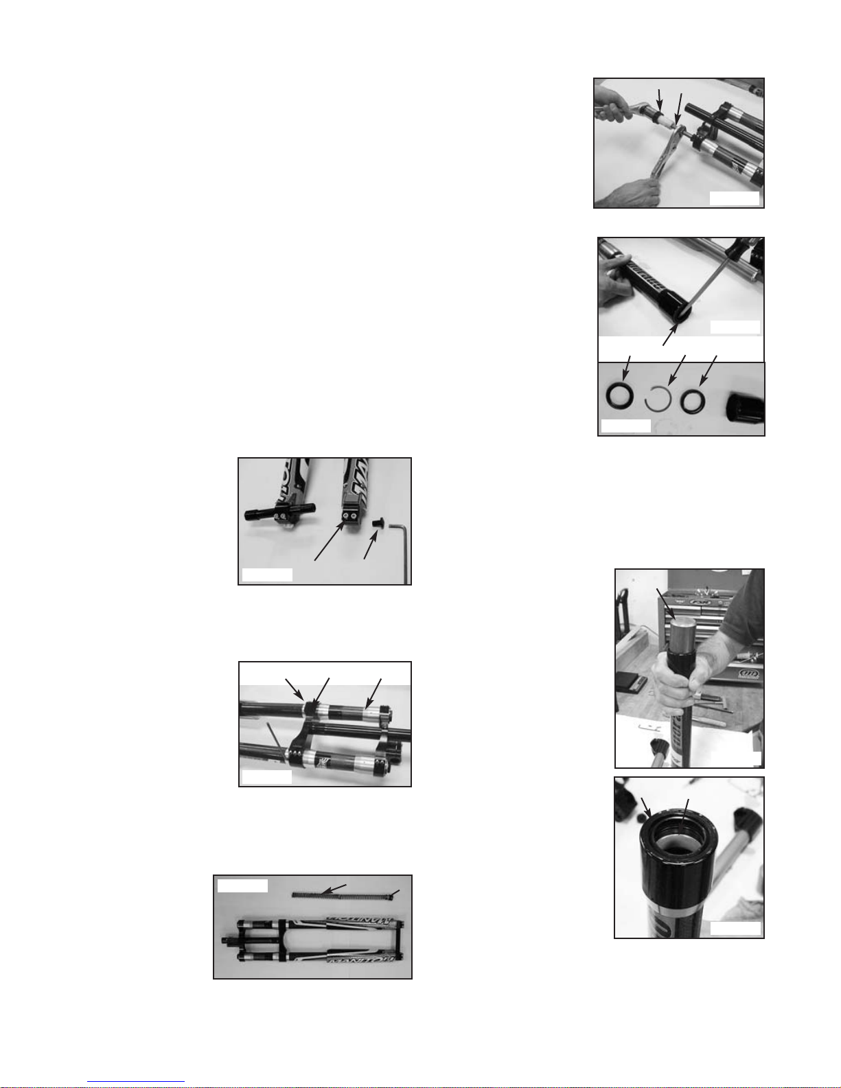
Hex Axle – Removal (Figure 1)
To remove the front wheel,
loosen the four dropout pinch
bolts (1) using a 5 mm hex
wrench. Loosen the button head
screw (2) on the right side of
the fork (while facing the fork)
using a 6 mm hex wrench. Push
the axle through the dropouts
from right to left.
Hex Axle – Installation
Reverse the steps above. Torque the button head screw to 15–20 in.-
lbs. (1.7–2.3 Nm). Torque the pinch bolts to 40–45
in.-lbs. (4.5–5.1 Nm).
Triple Clamp Removal (Figure 2)
Loosen the five pinch bolts (1)
using a 4 mm hex wrench and
slide the outer leg down through
the assembly.
Triple Clamp Installation
(Figure 2)
Wipe the aluminum sleeves (2)
on the outer legs and inside of
each triple clamp (3) with iso-
propyl alcohol. Position the
lower clamp on the flat surface
of the leg sleeves; the inside of the clamp must have full surface con-
tact with the sleeve. Torque the pinch bolts to 60–75 in.-lbs. (7.3–8.5
Nm).
Coil Spring Removal (Figure 3)
Use a 20 mm socket to remove the bottom right leg (facing the fork)
end cap (1). Pull the spring
stack (2) consisting of
one MCU, two springs and
connectors out of the
fork leg.
Coil Spring Service, Ride
Kit Installation (Figure 3)
Replace the spring in the
sequence shown, coating
the spring with a liberal amount of Maxima spring grease. Install the
end cap. Torque the end cap to 60–70 in.-lbs. (6.9–7.90 Nm).
Inner Leg Removal (Left Leg, Figure 4)
Remove the coil spring (see above) prior to removing the compression
rod. Unscrew the top cap (1)
with a 1 1/16" socket. Pull the
shaft out of the inner leg until it
stops; do not force. Clamp the
shaft using soft jaw blocks
(Answer tool P/N 064615). Using
a 1 1/16" socket, unscrew the top
cap off of the compression rod
(2). Pull the inner leg downward
from the outer leg.
Seal System Removal and
Bushing Replacement
(Figures 5 and 6)
There are two seals that make up
the sealing system on the bottom
of the outer carbon legs: an outer
(dust) seal to prevent contamina-
tion from the outside, and an
internal (oil) seal to retain lubri-
cation grease inside the fork. The
seals should be replaced if exces-
sive grease is found to be leaking
out of the fork or if on inspection,
excessive contamination is found
inside the outer leg. The seals
must also be removed if it
becomes necessary to replace the
bushings.
Remove the outer (dust) seal (1)
as shown (2). Pry out the metal circlip (3) and then the lower (oil)
seal (4). Discard both seals and circlip; they cannot be reused once
removed.
The bushings should be inspected for signs of wear (discoloration) or
tears on the surface. Bushings can be replaced using tools and
instructions found in Answer bushing removal and installation tools
PN 85-3909 and 85-3911.
Seal System Installation (Figure 7 and 8)
The two seals must be identified and
oriented before installation:
1. The oil seal is installed first
and is rubber on the outside
diameter. It is installed so that
the lip is pointing to the inside
of the outer leg. Install using
Answer seal installation tool
P/N 064000 (1).
2. Install the circlip into
the machined groove in the
outer leg.
3. The dust seal is installed last
and has metal on the outside
diameter. It is installed so that
the lip is pointing to the out-
side and metal surface towards
the circlip. Use the installation
tool to tap the seal into place.
The dust seal will be flush with
the rim (2) of the outer leg
when the seal system installa-
tion is complete.
Before reinstalling the inner leg
after servicing, liberally apply
Motorex grease to the upper and
lower outer leg bushings (3). Lightly
grease the inner legs before inser-
tion.
12
132
21
FIGURE 3
12
FIGURE 2
FIGURE 1
FIGURE 4
12 3 4
FIGURE 5
FIGURE 6
1
23
FIGURE 7
FIGURE 8
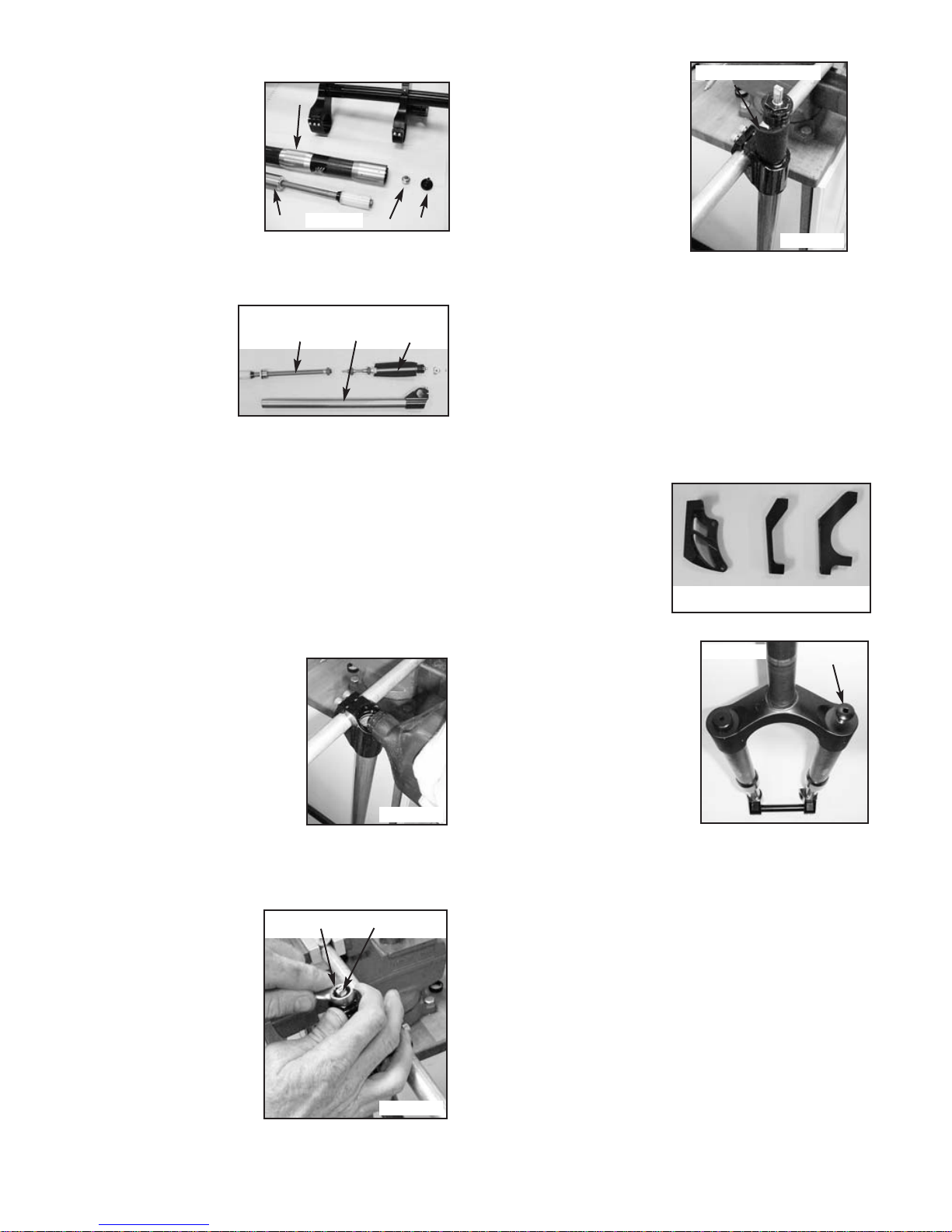
Damping System (Right Leg) Service – Leg Removal
(Figure 9)
It is recommended that the
right leg be removed before
service. Remove inner leg from
outer leg as follows:
1. Pull the rebound damper
adjuster knob (1) out of
the damper nut.
2. Remove the damper nut
(2) with an 8 mm hex
wrench.
3. Pull the inner leg (3) out
of the outer leg (4).
4. Remove the leg guard.
Damping System (Right Leg) Service – Leg Disassembly
(Figure 10)
Oil is removed from the
inner leg (3) by removing
the rebound and com-
pression assemblies to
ensure that all old oil is
removed from the sys-
tem. The compression
damping assembly (2) is
located at the bottom
(dropout) end and the
rebound assembly (1) is at the top.
1. Rebound Assembly Removal – With the rebound assembly end of
the leg pointing up (to minimize spilling damping oil), unscrew
the end cap and slowly pull out the assembly over a drip pan.
Pour out and discard the damping oil.
2. Compression Damping Assembly Removal – Unscrew the screw
holding the adjuster knob and remove the knob. Loosen the 13
mm adjuster needle lock nut (Figure 11, #1). Unscrew the end
cap using a 20 mm socket and slowly pull out the assembly over
a drip pan. A piece of black foam (compensator) may come out
as part of some production models.
Damping System (Right Leg) Service – Leg Assembly
(Figures 11, 12 and 13)
The damping system contains no air and when replacing damping oil,
must be bled to remove all air.
1. Install the rebound damper
assembly and torque the end cap
to 60–75 in.-lbs. (7.3–8.5 Nm).
2. Hang the leg vertical at a 45º
angle as shown in Figure 11. Place
a drip pan under the leg.
3. Fully extend the rebound damping
assembly shaft and fill with 5WT
Maxima fork oil (Answer PN 85-
3814) up to the bottom of the
inner leg threads. Cycle the
rebound damper shaft several
times, covering the open end of the leg with a rag. Allow the leg
to sit for two minutes to allow any air bubbles in the system to
rise to the top.
4. On the compression damping assembly, remove and discard the
foam compensator if one was there during damper removal. A
replacement is found in
tune-up kit PN 85-4953.
Remove the 13 mm
adjuster needle locknut
(1). Unscrew the needle
(2) until it is loose from
the assembly, but do not
remove.
5. Insert the compression damp-
ing assembly with its foam
compensator (if applicable)
wrapped tightly around the
shaft into the leg. Oil will be
displaced during this step. Be
sure that the foam does not
bunch up against the leg cap
and is fully inserted into the
leg. Screw in the assembly and
torque to 60–75 in.-lbs.
(7.3–8.5 Nm) using a
20 mm socket.
6. Install the adjuster needle and
13 mm lock nut and torque
to 10–15 in.-lbs. (1.1–1.7 Nm).
7. Install the compression adjuster knob.
8. Inspect the damper bleed process by compressing the rebound
shaft to the bottom out bumper. This is to ensure that the foam
compensator did not bind up internally to limit the travel. If it
does not fully compress, the system must be re-bled.
9. Fully extend the damper shaft and install the inner leg into the
outer leg. Lubricate the bushings and inner leg as specified
under Seal System Installation.
10. Install the damper nut using an 8 mm hex wrench and torque to
15–30 in.-lbs. (1.7–3.4 Nm).
11. Push the rebound damper adjuster knob into the nut until it
snaps in place.
Disk Brake Adapters (Figure 14)
There are three disk brake
caliper adapters included with
the DORADO forks:
(1) International Standard
(2) Post Mount – 6" Disk
(3) Post Mount – 8" Disk
DORADO SC (Single Crown) Fork
Service (Figure 15)
Service procedures for the DORADO SC
fork are the same as for the DH model
except for the method used to remove
the left inner leg. Leg removal is
accomplished by removing the 6 mm
button head cap screw (1) on top of
the crown and pulling the inner leg
out. Re-torque the screw to 15–30 in.-
lbs. (1.7–3.4 Nm) upon assembly.
321
4
FIGURE 9
FIGURE 10
132
12
123
1
FIGURE 11
FIGURE 14
FIGURE 13
FIGURE 12
FIGURE 15
1 Foam Compensator
This manual suits for next models
1
Table of contents
Other Manitou Bicycle Accessories manuals

Manitou
Manitou JACK DROPPER POST User manual

Manitou
Manitou Mezzer Pro User manual

Manitou
Manitou Axel Super 2004 User manual

Manitou
Manitou MARA PIGGYBACK User manual

Manitou
Manitou XVERT R User manual

Manitou
Manitou Jack SL Dropper Seat Post User manual

Manitou
Manitou DORADO EXPERT 37MM User manual

Manitou
Manitou 2001 MARS User manual

Manitou
Manitou R7 EXPERT User manual

Manitou
Manitou MATTTOC PRO User manual


