MantelMount MM720 User manual

U.S. PAT. NO. 8,864,092
MM720
Standard
Pull Down
TV Mount
Read this entire manual
before you begin.
Do not unpack
box contents
until verifying the
requirements listed
on page 4.
IMPORTANT:
MantelMount has three dierent adjustments
that must be made after the installation is
complete in order to operate properly.
ALL NEW FEATURE
!
WARNING!
This product contains small parts that
can be a choking hazard. Do not let
children play with any of these small
parts! Keep children away from the work
area during installation.
!
Caution
This product is intended to be installed
by professional installation contractors,
or persons familiar with the tools and
methods required for this installation.
If you are not sure about your ability
to perform this installation, you must
contact a professional. MantelMount
is not responsible for damage or injury
caused by incorrect installation or
improper use.
!
Caution
Do not let children operate, pull on, or
hang from MantelMount. Do not let
children push MantelMount upward
to the top position - this will cause the
mount to slam against the wall due to
the upward force of the springs. Only a
person tall enough to control the mount
all the way to the top should operate
MantelMount.
!
Caution
Do not use this product in any way, or
for any purpose, that is not specically
described in these instructions.
MantelMount is not responsible for
damage or injury caused by incorrect
installation or improper use.
INSTALLATION INSTRUCTIONS
If you need help, call 1.800.897.9755 ext.1
For missing/damaged parts or questions during installation,
contact our Customer Support team at 1.800.897.9755 ext.1or
support@mantelmount.com.
Customer satisfaction is our highest priority!
Watch an installation video or access a PDF of this manual at
MantelMount.com/FAQs/Specs and Manuals.
Contains important safety information – please save! MantelMount.com
The main bolt adjusts the lifting force to
accommodate dierent TV weights. All TVs
within the weight range should stay in the UP
and DOWN positions when adjusted properly.
The bottom travel stop is adjusted with two
screws so that the TV and mount do not
lower all the way into the mantel.
Your MM720 features the all new one handed
tilt adjustments handle, to easily tilt your TV
forward or back.
The side-to-side swivel stops are adjusted
with two screws so that the TV does not
swivel into the mantel.
MM720 Installation Instructions
2
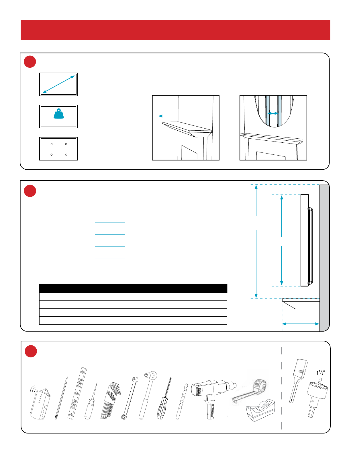
1 Verify TV and mount space meet these criteria:
VESA
Width: 200-700mm
Height: 100-500mm
SCREEN SIZE
50" to 90"
(Diagonally)
2 Verify MantelMount will fi t the wall space.
VESA
Width: 200-700mm
Height: 100-500mm
50"– 90"
VESA COMPLIANT
Up to 600mm X 600mm
WEIGHT CAPACITY
25 to 115 LBS.
(Including Sound Bar)
WOOD STUDS FOR MOUNTING
Studs Maximum 28" apart;
Wall Covering Maximum 5/8"
MANTEL DEPTH
18" MAXIMUM
VESA
Width: 200-700mm
Height: 100-500mm
MAX 25-115 LBS
18" MAX
WALL SPACE
HEIGHT
TV HEIGHT
MANTEL DEPTH
If Mantel Depth is: Required Vertical Space is:
Less than 8" TV height + 2"
9" – 11" TV height + 4"
11" – 14" TV height + 6"
14" – 18" TV height + 9"
A. Use the reference diagram (right) and chart (below) to write down the following
measurements (in inches):
Wall Space Height
:(Distance from mantel to ceiling/crown molding.)
TV Height:
(Include sound bar height if placing below TV.)
Mantel Depth:
(Distance mantel extends away from the wall.)
Required Vertical Space:
(Calculation from chart below.)
B. If the Required Vertical Space is less than or equal to the Wall Space
Height, then MantelMount will t the wall space.
STUDS
MAX 28"
APART
3 Verify you have the required tools.
4–5mm
10–14mm
AWL DRILL BIT POWER DRILL
PENCIL LEVELSTUD FINDER WRENCH SOCKET WRENCHALLEN WRENCHES TAPE MEASURER TAPE DISPENSER
OPTIONAL
PAINT
BRUSH
HOLE SAW
PHILLIPS
7/32"
BEFORE INSTALLATION
3
{02} x4
M5x30
{01} x4
M5x12
{03} x4
M5x40
{05} x4
M6x30
{04} x4
M6x16
{06} x4
M6x40
{08} x4
M8x25
{07} x4
M8x15
{09} x4
M8x45
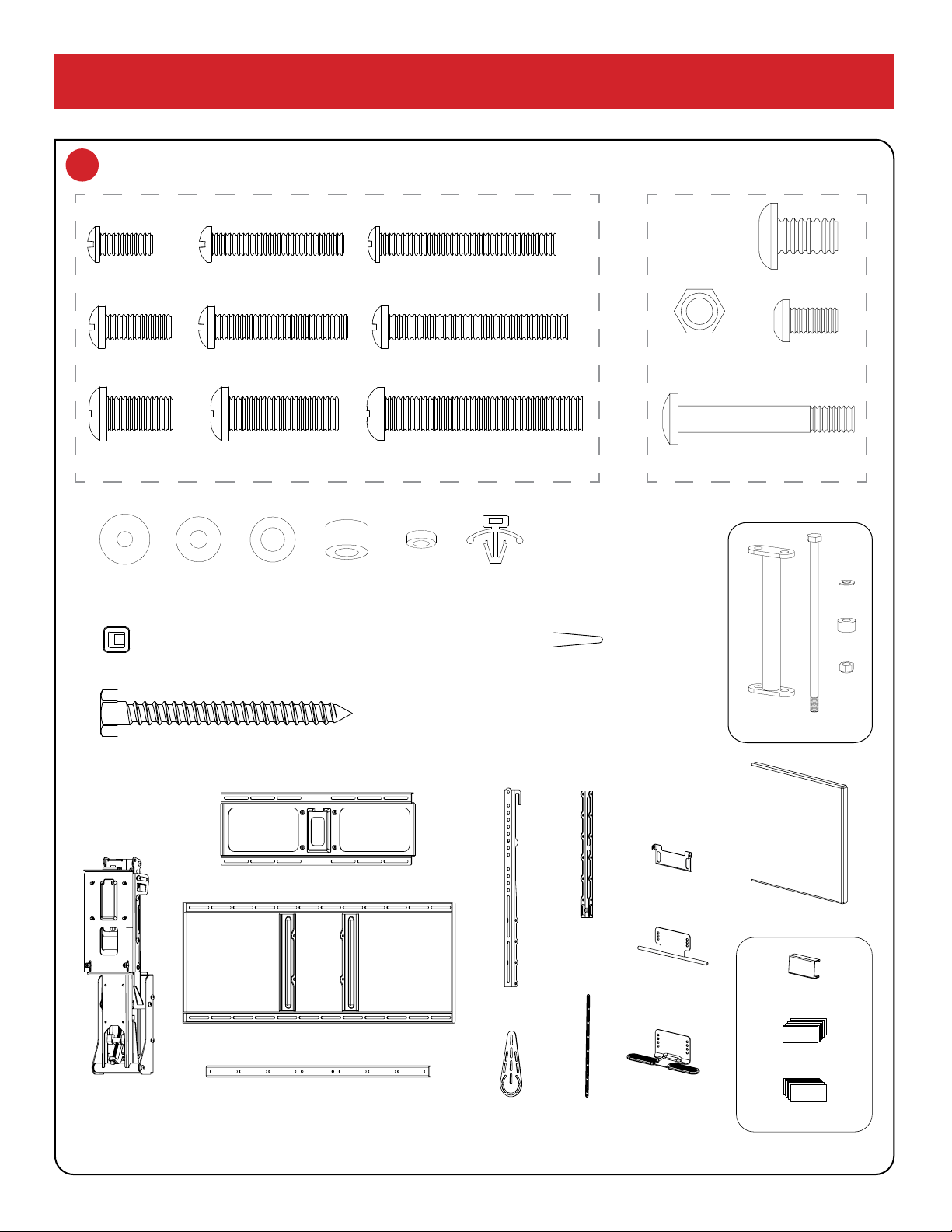
4 Verify all parts are included.
If any parts are missing or damaged, contact Customer Support at 1-800-897-9755 x1 before installing.
SILVER SCREWS FOR BACK OF TV
{10} x4
M5-M6
{19} x2
{66} x2
{11} x8
M8
{12} x12
Spacer
{19} x2
{10} x4
M5-M6
{19} x2
{66} x2
{11} x8
M8
{12} x12
Spacer
{66} x2
Spacer
{10} x4
M5-M6
{19} x2
{66} x2
{11} x8
M8
{12} x12
Spacer
{10} x12
M5-M6
{10} x4
M5-M6
{19} x2
{66} x2
{11} x8
M8
{12} x12
Spacer
{11} x8
M8
{10} x4
M5-M6
{19} x2
{66} x2
{11} x8
M8
{12} x12
Spacer
{12} x12
Spacer
{10} x4
M5-M6
{11} x8
M8
{12} x12
Spacer
{15} x16
M6x10
{18} x4
M6x40
{17} x4
Lag Bolt
{20} x1
Safety Bolt
{27} x1
Safety Nut M8
{23} x8
Locknut M6
{22}
x2
Anchor
{24} x4
Cable Ties
{14} x4
HEX M8x15
{53} x1
Center
Handle
{57} x2
Wall Cover
{31} x2
Vertical
Brace
{59} x2
Sound Bar
Wing
{30} x2
Brace
Extender
{32} x2
Wall Plate
{55} x1
Horizontal
Brace
{33} x1
TV Brace
{35} x1
Lifting
Mechanism
Black Parts for Mount
Silver Screws for back of TV
{02} x4
M5x30
{01} x4
M5x12
{03} x4
M5x40
{05} x4
M6x30
{04} x4
M6x16
{06} x4
M6x40
{08} x4
M8x25
{07} x4
M8x15
{09} x4
M8x45
{22} x2
Anchor
{33} x1 TV Brace
{32} x1 Wall Plate
{55} x1 Horizontal Brace
{17} x4
Lag Bolt
{20} x1
Safety Bolt
{22}
x2
Anchor
{24} x4
Cable Ties
{17} x4 Lag Bolt
{35} x1
Lifting Arm
{31} x2
Vertical Brace
{53} x1
Center Handle
{16} x2
Sound Bar Wing
{65} x1
Tilt Puller
{54} x4
Tilt Straps
{67} x1
Hideaway Handle
{30} x2
Brace
Extender
{17} x4
Lag Bolt
{20} x1
Safety Bolt
{22}
x2
Anchor
{24} x4
Cable Ties
{24} x4 Safety Ties
23030
x1
12283
x1
23058
x1
12187
x1
14126
x2
BEFORE INSTALLATION
{63} x8 Wall Clips
{25} x8 Velcro Hook
{26} x8 Velcro Loop
{57} x2 Wall Covers
{15} x24
M6x10
{14} x4
M8x16
{18} x4
M6x40
{23} x16
Locknut M6
BLACK PARTS
FOR MOUNT
Thread patterns may vary.

MM720 Installation Instructions
4
MM720 INSTALLATION STEPS
STEP 1 Attach Braces to TV
.....................................PAGE 5
STEP 2 Determine Wall Placement
..............................PAGE 8
STEP 3 Attach Mount to Wall
....................................PAGE 11
STEP 4 Attach TV to Mount
.....................................PAGE 15
STEP 5 Make Final Adjustments
.................................PAGE 18
CAUTION / WARNING SPECIAL NOTE REQUIRES TWO PEOPLE
DO NOT
HELPFUL INFORMATION
Symbols Used in this Manual
Installation Tips & Videos: http://mantelmount.com/install-tips
Questions during installation? Contact Customer Support:
Two people required for parts of this installation.
This product is intended to
be installed by professional
contractors or persons
familiar with the tools and
methods required for this
installation.
If you are uncertain about
your ability to perform this
installation, please contact a
professional.
Do not use this product in any
way or for any purpose that is
not specically described in
these instructions.
Keep children away from the
work area during installation.
This product contains small parts,
please keep out of reach from
children.
Do not let small children
pull on or hang from
MantelMount.
Only persons tall enough to
control the product all the
way to the top/raised position
should operate MantelMount.
Do not allow small children to
push MantelMount upward to
the top position. This will cause
the mount to slam against the
wall due to the upward force of
the springs.
WARNINGWARNING WARNINGWARNING CAUTIONCAUTION
Do not use this product for
purposes not specically
described in these
instructions.
MantelMount is not responsible
for damage or injury caused
by incorrect installation or
improper use.
MantelMount is not responsible
for damage or injury caused
by incorrect installation or
improper use.
CAUTIONCAUTION
Do not remove the gas
springs or any bolts that hold
the Lifting Arm together.
WARNINGWARNING
U.S. Pat. No. 8,864,092
For more information on MantelMount patented technology visit: www.mantelmount.com/pages/patents

5Customer Support 1.800.897.9755 x1 suppor[email protected]
Select Screws and Spacers.
If Spacers {12} are required, choose one of these Screw
combinations shown with maximum Spacer usage.
{02}
{01} {10}
{10}
{10}
{10}
{11}
{11}
{11}
{12}
{12}
{10} {12}
{10} {12}
{12}
{12} {12}
{12} {12}
{12} {12}
{12}
{12}
{03}
{05}
{04}
{06}
{08}
{07}
{09}
M5
M6
M8
Test-t Brace components on back of TV.
Place TV screen-side down on a at, blanketed surface.
Lay out components to check assembly conguration. If
installing a sound bar, refer to STEP 1.8.
1.1
STEP 1
Attach Braces
to TV
*
Determine if TV has a at or irregular back.
An irregular back will require Spacers {12} and longer
Screws to ll spaces between the Vertical Brace {31} and
the TV. The Braces must be parallel to television screen.
Flat Back TV
Irregular Back TV {12}
{12}
{31}
{31}
Irregular Back TV
(Recessed Threads)
{31}
{31}
{30}
{53} {55}
{31}
{30}
BACK
OF TV
1.2
1.3
In order for the TV to hide the Mount on the wall, the
Braces must be at least 4” higher than the bottom of TV
(or Soundbar if one is installed).
If you are using an RB100 Recess Box then they must be
more than 6“ higher to hide the Recess Box.
MM720 Installation Instructions
6
If the lower VESA holes are less than 4" from the
bottom of the TV:
Connect the Vertical
Braces {31} through the
UPPER VESA holes only,
so that the bottom of
the braces are between
4" to 10" from the
bottom of the TV. *
If the only option is
to attach the Vertical
Braces to the Upper
Vesa holes through a
slot: 1) Hand-thread
the screw through
the slot; 2) slide the
Vertical Brace upward
until the screw meets
the bottom of the
slot; and 3) tighten
the screw.
You must attach the
Brace Extenders {30}
to the Vertical Braces
as described in STEP
1.7. However, you
must also attach the
LOWER VESA hole
through the Brace
Extender as shown.
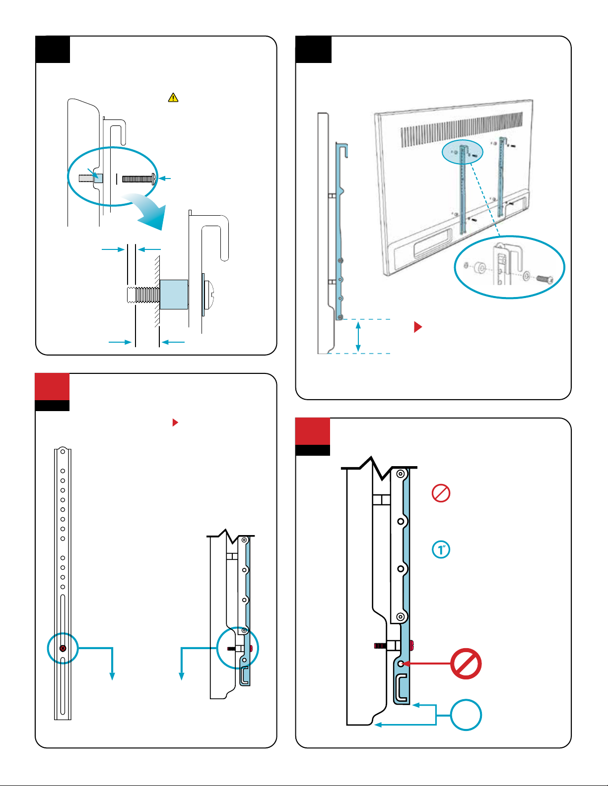
Hand-thread screw combination into the TV.
Ensure there is adequate thread engagement
without hitting the bottom of threaded insert.
Do not use screws that
are too long for the TV’s
threaded inserts because
it may damage internal
components!
MUST LEAVE
A GAP IN
THREADED
TV INSERT
MAXIMIZE THREAD
ENGAGEMENT FOR
STABILITY
AFTER ASSEMBLY
(ENLARGED)
{12}
CAUTIONCAUTION
TV SCREW
Lower VESA hole
with screw in place.
1.4
OPTIONAL
1.6
Attach the Vertical Braces to the back of TV.
Install the Vertical Braces {31} so that the bottoms of the
braces are between 4" to 10" from the bottom of TV,
(*or Soundbar if one is installed) centering the braces
vertically as much as possible.
{31}
4 to 10
INCHES *
SIDE VIEW
{31}
{31}
VERTICAL BRACES MUST ALWAYS
BE INSTALLED HIGHER THAN THE
BOTTOM OF THE TV.
If the lower VESA holes are less than
4" from the bottom of the TV, go to
STEP 1.6; otherwise skip to STEP 1.7.
*
If installing this mount with a MantelMount RB100 Recess Box, the bottom
of the Vertical Brace must be more than 6” and up to10” from the bottom of
TV (or more than 6” from the bottom of the Soundbar if one is installed).
1.5
{31}
Upper VESA hole
with screw in place
.
Rules for mounting the Extenders {30}
DO NOT use the
lowest hole on
the extender (30)
If you are NOT
using a Soundbar,
the Extenders {30}
must be 1 inch above
the bottom of the TV
to leave room for
the Handle.
OPTIONAL
1.7
A:
B:
1
”
DO NOT use
this lowest hole.
7Customer Support 1.800.897.9755 x1 suppor[email protected]
{55}
{15}
{15}
{30}
{31}
{31}
{30}
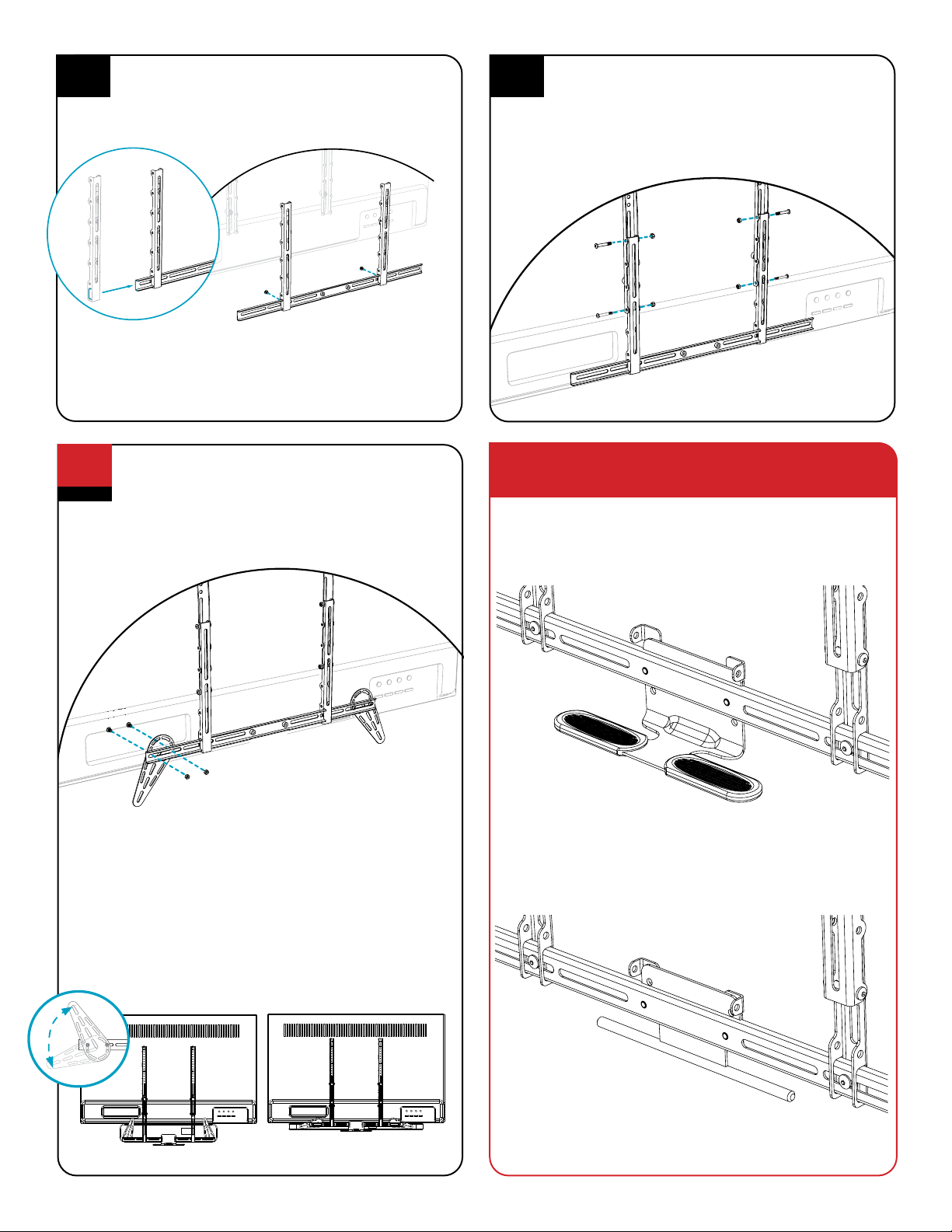
Attach the Horizontal Brace to Brace Extenders.
Slide one Brace Extender {30} onto the left end of the
Horizontal Brace {55}, then slide the other Brace Extender
onto the opposite right end.
Align the Brace Extenders with the Vertical Braces (that are
already mounted to the back of the TV) while positioning the
Horizontal Brace so that it extends an equal amount on either
side of the Brace Extenders. Attach Horizontal Brace to Brace
Extenders w/Screws {15}.
{30}
{55}
Attach Brace Extenders to the Vertical Braces.
Slide the Brace Extenders {30} (with the Horizontal Brace
{55} now attached to them) onto the Vertical Braces {31}.
Position it so that the Horizontal Brace will be hidden by
the TV. Use Screws {18} and Nuts {23} to attach.
{23}
{18}
{23} {23}
{31}
{31}
{30}
{30}
{55}
{18}
{18}
1.9
1.8
{15}
If installing a sound bar, attach the Sound Bar Wings.
Use Screws {15} and Nuts {23} to attach the Sound Bar
Wings {16} to the Horizontal Brace {55}. Position the
Wings to t the mounting holes of the sound bar.
Install sound bar. See below for Sound Bar Wing
installation information.
{15}
{15}
{16}
{16}
{55}
{23}
Arrange Sound Bar Wings and sound bar to work with the
Heat-Sensing Center Handle.
The Sound Bar Wings may be positioned and rotated so that
the Center Handle {53} will reach below the sound bar.
For example, if a sound bar is tall, the Brace Extenders {30}
and Horizontal Brace can be attached lower down on the
Vertical Braces toward the bottom of the sound bar while the
Wings point upwards in order to align with the sound bar’s
installation holes.
TALLER SOUND BAR WIDER SOUND BAR
WIDE
TALL
WIDE
TALL
OPTIONAL
1.10
The MM720 was designed with two tilt handle conguration
options. Both options will allow you to tilt your television
equally. Choose the handle conguration that works best for
your mounting situation. DO NOT install BOTH HANDLES.
Option B: Hideaway Handle conguration.
Allows for the handle to be hidden away behind the television while
still giving access to the mounts tilt feature.
Option A: Heat-Sensing Handle Conguration.
Our patented Heat-Sensing Handle turns red if the temperature
above the replace exceeds a safe 110° F – a visual cue that either
the TV needs to be raised to the UP position or the replace needs
to be turned o.
Tilt Handle Confi guration Options
MM720 Installation Instructions
8
NOTE The tilt function does not work with the Recess Box RB100, because the TV will be too close to the wall. If you intend to
use the RB100 Recess Box on with your MantelMount installation DO NOT use parts {65} or {54}.
Attach the Heat Sensing Handle {53} and the Tilt Puller
{65} as shown, using Spacers {66}, Washers {19} and
Screws {15}. The Spacers {66} MUST BE located inside
the slots of the Tilt Puller. The Spacers will clamp tightly
against the Heat Sensing Handle while still allowing the
Tilt Puller to slide freely.
The Heat Sensing Handle should be within one inch
BELOW the bottom of the TV or Soundbar so that it can
be easily grabbed to move the TV.”
Attach two Tilt Straps {54} to the Tilt Puller {65} using
two screws {15} and two nuts {23}. When attaching the
straps together be sure the screws
and nuts are attached to the end of the straps.
IMPORTANT NOTE: The Screws {15} must be on the
OUTSIDE, and the Nuts {23} must be on the INSIDE.
1.11A Option A: Heat Sensing Handle
Attach the Hideaway Handle {67} and the Tilt Puller {65}
as shown, using Spacers {66}, Washers {19} and Screws
{15}. The Spacers {66} MUST BE located inside the slots
of the Tilt Puller. The Spacers will clamp tightly against
the Hideaway Handle while still allowing the Tilt Puller
to slide freely.
The Hideaway Handle should be within one inch ABOVE
the bottom of the TV or Soundbar so that it can be easily
grabbed to move the TV.”
Attach two Tilt Straps {54} to the Tilt Puller {65} using
two screws {15} and two nuts {23}. When attaching the
straps together be sure the screws
and nuts are attached to the end of the straps.
IMPORTANT NOTE: The Screws {15} must be on the
OUTSIDE, and the Nuts {23} must be on the INSIDE.
1.11B Option B: Hideaway Handle
{53}
{65}
{66}
x2
{19}
x2
{15}
x2
{15}
x2
{54}
x2
{23}
x2
{67}
{65}
{66}
x2
{19}
x2
{15}
x2
1.11 - Tilt Handle Confi guration Options:
(Choose Your Handle Option)
Heat Sensing Handle: OPTION A
Hideaway Handle : OPTION B

9
STEP 2
Determine
Wall Placement
Measure the distance
from the bottom of the
Vertical Braces {31} (not
the Extenders) to the
bottom of the TV/
sound bar.*
DEPTH OF MANTEL
{31}
DISTANCE
FROM 2.1
DISTANCE
Minimum distance between mantel
and lower wall plate holes
MEASURE
THIS
DISTANCE
Determine the minimum vertical position of the Wall Plate.
Use the Look-up Table below to nd the minimum distance between the mantel and
the bottom of the lower Wall Plate {32}. This will be the intersection of the distance
from STEP 2.1 and the mantel depth. Write the minimum distance in the box below.
Most customers want their TV mounted as close to the mantel as possible. If this
describes you, go directly to STEP 2.4.
However, if you want the TV higher on the wall (such as centered between the
mantel and ceiling) e.g. for extra space on the mantel for pictures or a center speaker,
continue to STEP 2.3.
VALUE FROM
LOOK-UP TABLE
*If installing this mount with a MantelMount
RB100 Recess Box, the bottom of the Vertical
Brace must be more than 6” from the bottom
of TV (or 6” from the bottom of the Soundbar
if one is installed).
2.1 2.2
10
9
8
7
6
5
4
8"OR LESS
10.5
9.5
8.5
7.5
6.5
5.5
4.5
9"
11
10
9
8
7
6
5
10"
11.5
10.5
9.5
8.5
7.5
6.5
5.5
11"
12
11
10
9
8
7
6
12"
12.5
11.5
10.5
9.5
8.5
7.5
6.5
13"
12.3
12.3
11.3
11.3
9.25
8.25
7.25
14"
14
13
12
11
10
9
8
15"
15.3
14.3
13.3
12.3
11.3
10.3
9.25
16"
16.8
15.8
14.8
13.8
12.8
11.8
10.8
17"
19
18
17
16
15
14
13
18"
7"
8"
9"
10"
4"
5"
6"

MM720 Installation Instructions
10
(E)
Distance between
mantel and lower
wall plate holes
OPTIONAL Some customers want the TV centered between the mantel and the ceiling or crown molding. Others want enough space below the TV
for pictures or a center speaker.
The TV’s position on the wall is directly related to the placement of the lower Wall Plate. To determine exactly where to place the lower
Wall Plate, choose an option below that best describes your scenario and ll in the boxes.
NOTE: Distance “E” below must always be at least the minimum distance in STEP 2.2
Determine a higher vertical position of the Wall Plate.
Find the center of your mantel and the centers
of two studs.
Measure and mark the center line of the mantel onto the
wall with tape.
Next, use a stud nder to locate two studs, one on each
side of the centerline. (If you prefer to use one center stud
alone, see “Mount Space”in the Troubleshooting Tips on
page 21.)
Then, at the height from either Step 2.2 or 2.3, locate the
center of the stud(s) by poking a sharp awl or nish nail
through the drywall to nd each stud edge. Mark these
center spots on the wall. Lag Bolts must be installed into
the CENTER of the studs in STEP 3.1.
AWL
STUD FINDER
C
L
Cutout shown
for reference
Option 1: I want the TV centered between the mantel
and ceiling/crown molding.
1. Record measurements already taken:
Wall Space Height from pg. 2 (A)
TV Height from pg. 2(B)
Distance from STEP 2.1 from pg. 8(C)
2. Subtract the TV Height (B) from the Wall Space Height (A),
then divide by 2.
(A) – (B) =
3. Add (C) and (D) to determine how many inches above
the mantel to place the lower Wall Plate holes.
(C) + (D) =
Option 2: I want the TV a specic distance above
the mantel.
1. Record distance from STEP 2.1 from pg. 8(C)
2. Write the specic number of inches
you want between the mantel and
the TV (or TV with sound bar):
3. Add (C) and (D) to determine how many inches above
the mantel to place the lower Wall Plate holes.
(C) + (D) =
2
(D)
(E)
(E)
(D)
OR
Align the slots on the Wall Plate {32} pointing upwards.
Center and level the plate above the mantle and position
the height using the table in STEP 2.2. Mark the 4 spots
for lag bolts directly on center of the studs.
Pre-drill the 4 holes with 7/32” drill bit to a depth of 2.5
inches (65mm) including wall covering.
Note: Wall covering (drywall) must not exceed
5/8” thickness.
2.3
2.4 2.5
2.6
Minimum Height
from STEP 2.2
SLOTS UP
11
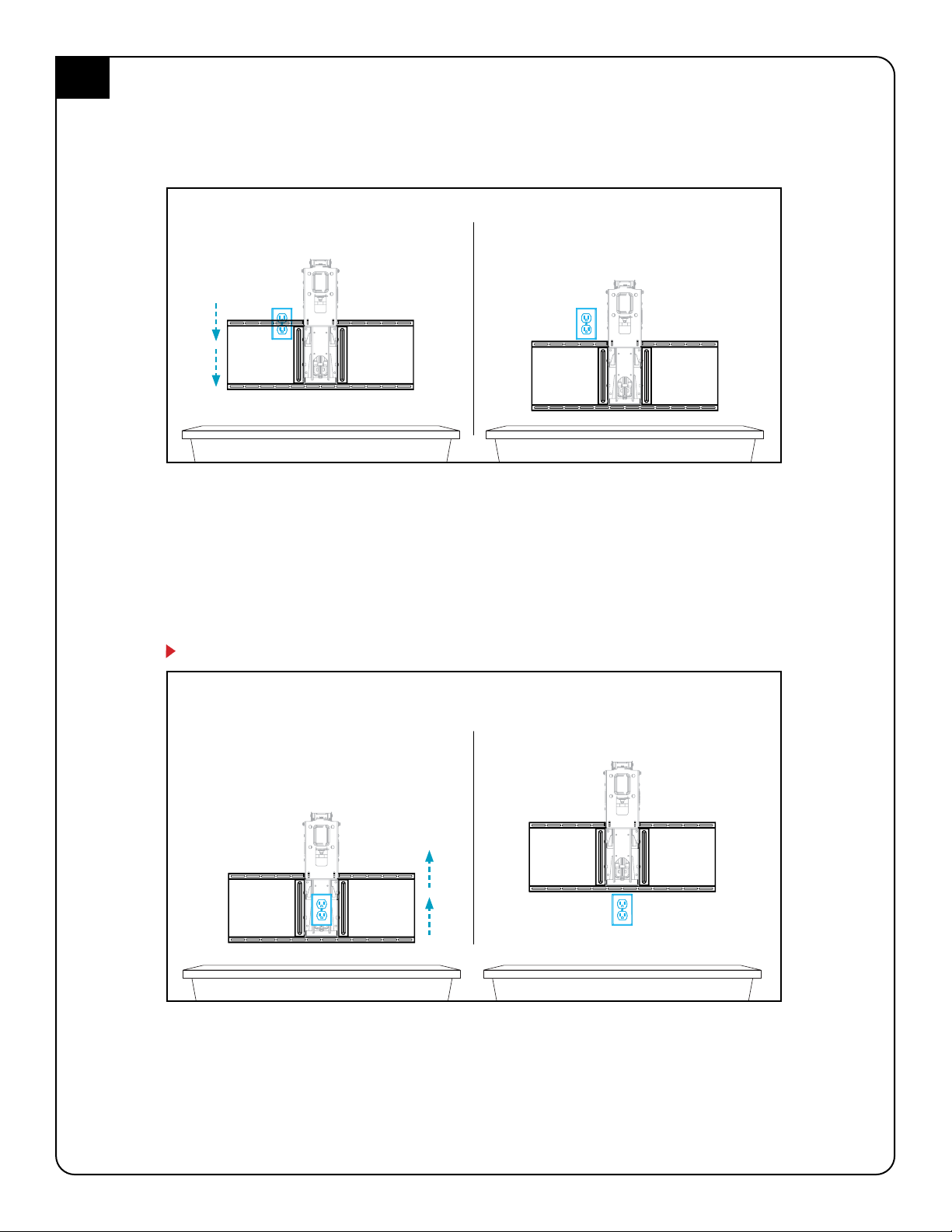
BEFORE
Wall plate impeded by outlet.
BEFORE
If the wall plate sits directly behind lifting
arm wall plate must be moved up.
After
Wall Plate lowered to clear outlet.
After
Wall plate moved up to clear outlet.
If necessary, move Wall Plates to clear an outlet.
If a Wall Plate installation is impeded by an electrical outlet (or other) and professionally relocating the outlet is
impossible, try one of these two options:
Move Wall Plates up or down to clear the outlet. As long as you don’t place the LOWER Wall Plate below the
Minimum Distance (Step 2.2) or above the Maximum Distance (step 2.3), MantelMount will still function properly.
Simply move the Wall Plates up or down enough to clear the outlet, leaving them as close as possible to the
originally planned vertical positions.
IMPORTANT: You must now move the Vertical Braces {31} on the back of the TV using the same number of inches
used to move the Wall Plates (e.g., move the Vertical Braces down 2" if the Wall Plates were moved down by 2" ).
The bottom of the Vertical Braces must remain between 4 to 10 inches from the bottom of the TV.
Move the Wall Plates up enough to clear the outlet, leaving them as close as possible to the originally planned
vertical positions.
IMPORTANT: You must now move the Vertical Braces {31} on the back of the TV using the same number of inches
used to move the Wall Plates (e.g., move the Vertical Braces up 2" if the Wall Plates were moved up by 2" ).
The bottom of the Vertical Braces must remain between 4 to 10 inches from the bottom of the TV.
NOTE: If outlet is directly behind the Lifting Arm, the only solution is to move the Wall Plates up.
2.7
MM720 Installation Instructions
12
Attach the Wall Plate {32} using Lag Bolts {17} and
Washers {11} directly into the centers of the studs.
3.1
: Do Not over tighten Lag Bolts {17}. Tighten
only until the washers are rmly against the wall plate. Damage
due to over tightening can cause property damage or injury.
STEP 3
Attach Mount
to Wall
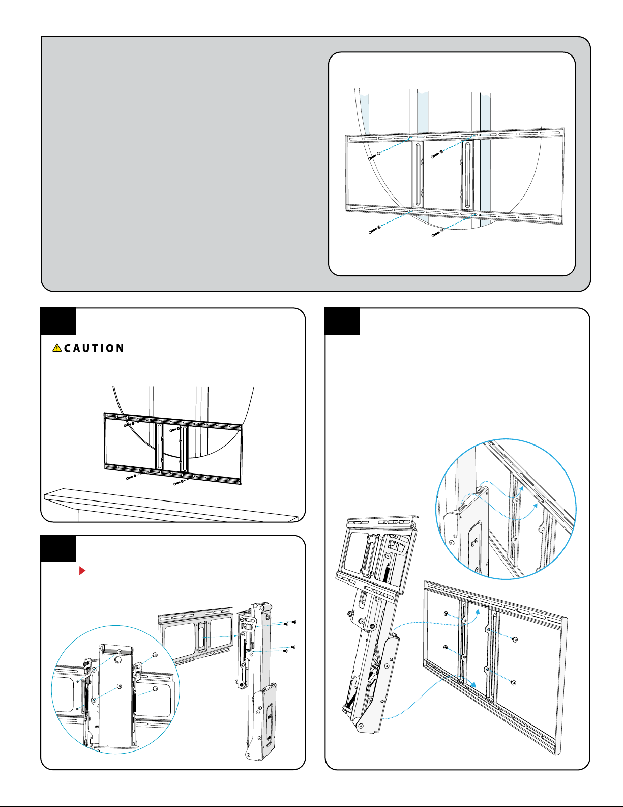
Attach the TV Brace {33} to the lifting arm. Level the TV
Brace and tighten the 4 screws {15}.
NOTE: After TV is mounted to bracket you may need
to adjust these screws to make nal Post-Leveling
adjustments (Step 5.4).
3.2
Insert top tabs of Lifting Mechanism {35} into the slots of
Wall Plate {33} then slide the bottom into position. Align
all four holes and install Screws {14}. Insert all 4 screws
before tightening securely.
IMPORTANT: When handling the Lifting Mechanism {35}
DO NOT damage or scratch the rods of the Gas Springs.
3.3

13
OPTIONAL
3.4
STANDARD
30° BOTH
DIRECTIONS
OPTIONAL
80° BOTH
DIRECTIONS
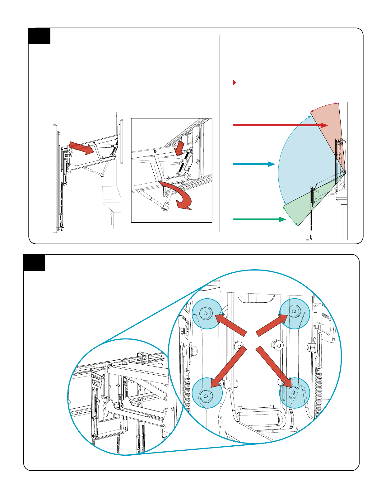
Determine the desired swivel setting.
MantelMount is designed to swivel 30° left and 30° right.
Most TVs will reach the wall within this amount of swivel.
For situations where more swivel is desired, the SRE00
Side Swivel Kit that provide 80 degrees in both directions.
This situation is only for a small TV and a mounting
situation that does not have a mantel.
Note: The Auto-Straightening feature does not work with
the SRE00 Swivel Kit. The TV will need to be manually
straightened so it’s parallel with the wall when raising it
to the UP position
OPTIONAL STEPS AND FEATURES
The following steps are optional. Please review to determine if
they are useful to your installation. If not, skip ahead to Section 4.
This step is OPTIONAL. SRE00 NOT REQUIRED IF MOUNTING OVER A FIREPLACE.If you do not need to add the Side Swivel Kit, skip ahead to Section 4.
Note: The SRE00 is recommended only for installations of the MantelMount that require maximum swivel in both Directions, such as a mount that is
attached to a post or located at a corner. Also, when the mount is in the stowed, at position this extender will shift the TV slightly to one side or the other.
The wall attachment can be shifted sideways to compensate for this if a center installation is desired.
SRE00 Swivel Range Extender
(Optional)
Before starting this next optional step – Installing the SRE00
Swivel Range Extender –You MUST pull the Lifting Arm down
and engage the Safety Latches. See step 4.1 before proceeding.
SRE00 Contents:
23030
(x1)
12283
(x1)
14126
(x2)
23058
(x1)
12187
(x1)
Engaging the Safety Latches. In this next step of the installation process you will be required to simultaneously engage the Safety
Latches. This will allow you to safely perform the rest of the installation.
Engaging the Safety Latches will require two people. The rst person must rmly pull down the TV Brace until the Lifting
Mechanism is in the horizontal position. DO NOT HIT THE MANTLE! The second person must simultaneously lower both of the Safety
Latches from the stowed position under the upper lifting arm and into the Latches catch slots. SLOWLY raise the TV Brace while
at the same time pushing the Safety Latches INWARD and REARWARD until they engage the slots in the Lower Arm. The Lifting
Mechanism will now stay at a horizontal position.
3.4
The Safety Latches must always be engaged
or disengages simultaneously.
WARNING: For your safety always
engaged or disengage Safety Latches by
reaching underneath the mount.
WARNING: DO NOT reach through
the arm to grab the Safety Latches!
Grab from below the Arm only!
MM720 Installation Instructions
14
OPTIONAL
3.8
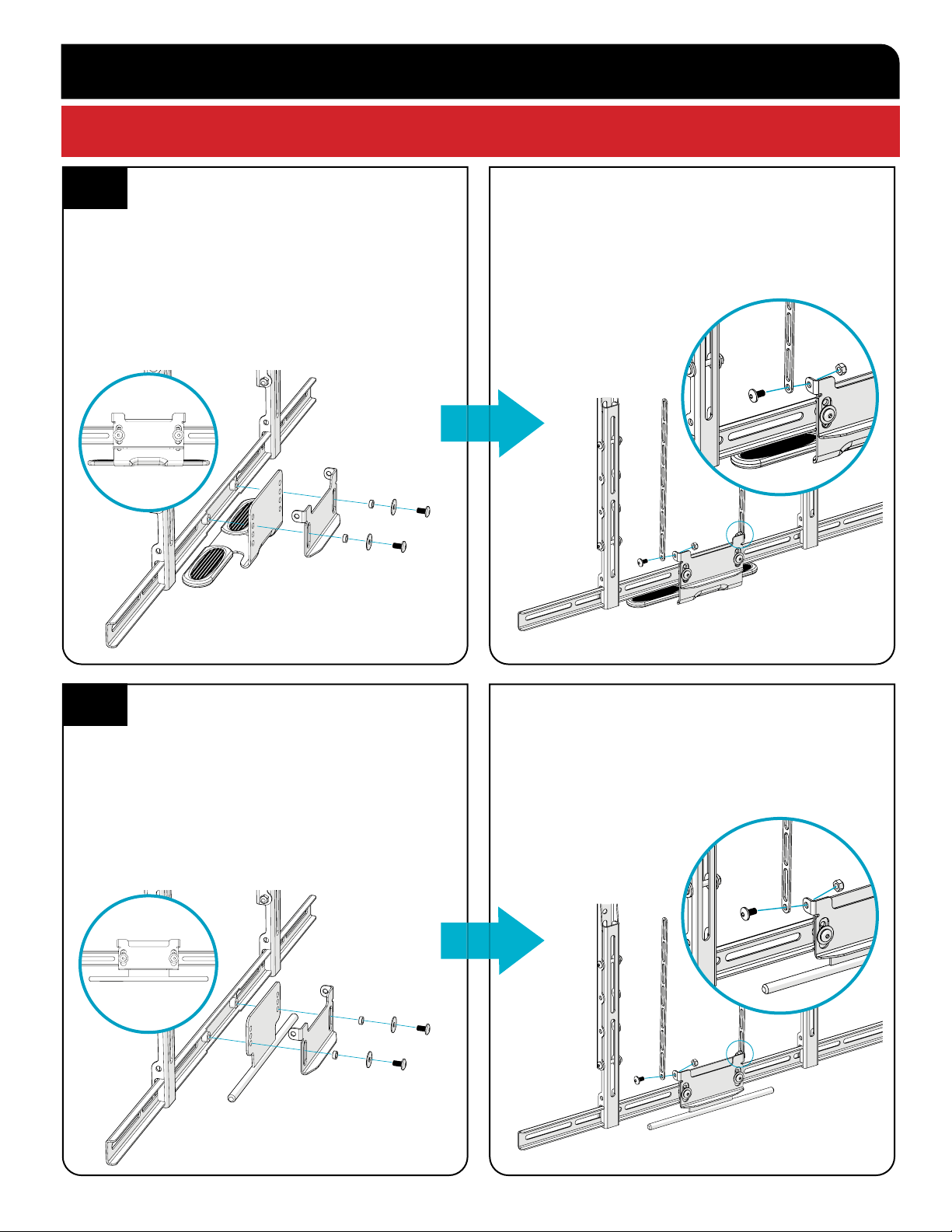
Tighten the Locknuts at the bottom until the swivel
movement is snug but not tight, so that the TV holds
all positions during swivel.
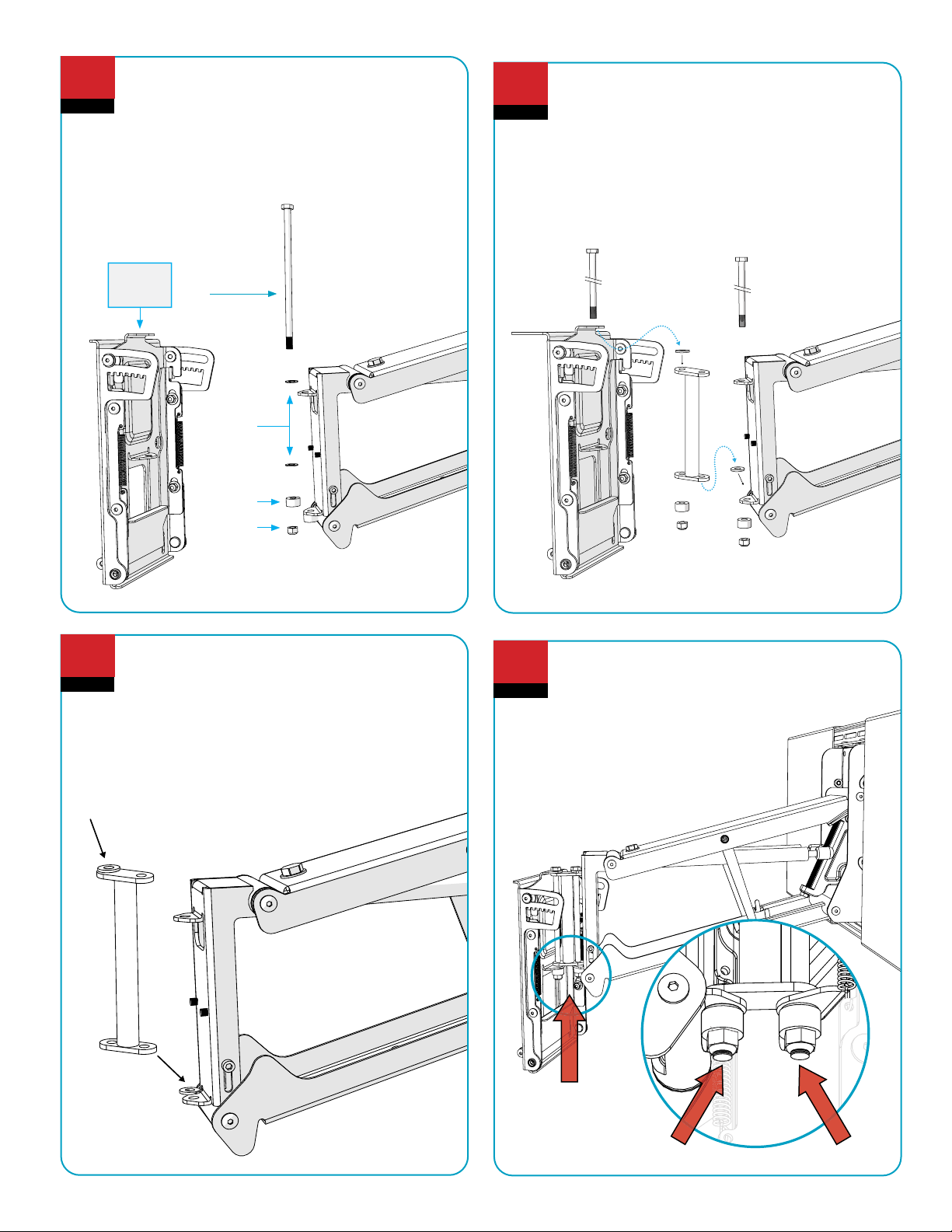
OPTIONAL
3.6
Re-assemble the Swivel Plate to the Arm in the order
shown here. The Swivel Bridge ts inside the tabs of
the Lifting arm and the Swivel Plate
OPTIONAL
3.7
Be sure to place one Washer on the lower tab of
the lifting arm. The Swivel Bridge will rest on this
washer.
Place the other Washer on the top of the opposite
side of the Swivel Bridge as shown. The Swivel Plate
will rest on this Washer.
OPTIONAL
3.5
Installing the optional SRE00 Swivel Kit. Before
installing the optional SRE00 Swivel Kit you will
rst need to pull down the mount and engage the
Safety Latch ( See Step 3.4 before attempting ).
Remove the Swivel TV Plate (Tilting or non-Tilting).
You will reuse all of the components. This kit
includes a duplicate set of hardware to complete the
installation.
Tilt
Swivel
Plate
12283 (x1)
23058 (x1)
12187 (x1)
12167 (x4)

15Customer Support 1.800.897.9755 x1 suppor[email protected]
STEP 4
Attach TV
to Mount
4.1
Preset the lifting force.
Turn the main bolt CLOCKWISE (while looking at the head of the bolt from underneath) as shown to pull the Gas Springs
DOWN for heavy TVs. Rotate the bolt the other way for less lifting force for lighter TVs.
See the diagram below for a preset estimate for the Gas Springs. The lightest lifting force is at the top, and the heaviest is down
just below the middle of the bolt threads.
DO NOT adjust all the way to the bottom. That position is only to remove the Gas Springs.
25LB
50LB
75LB
100LB
Weight of TV
MM720 Installation Instructions
16
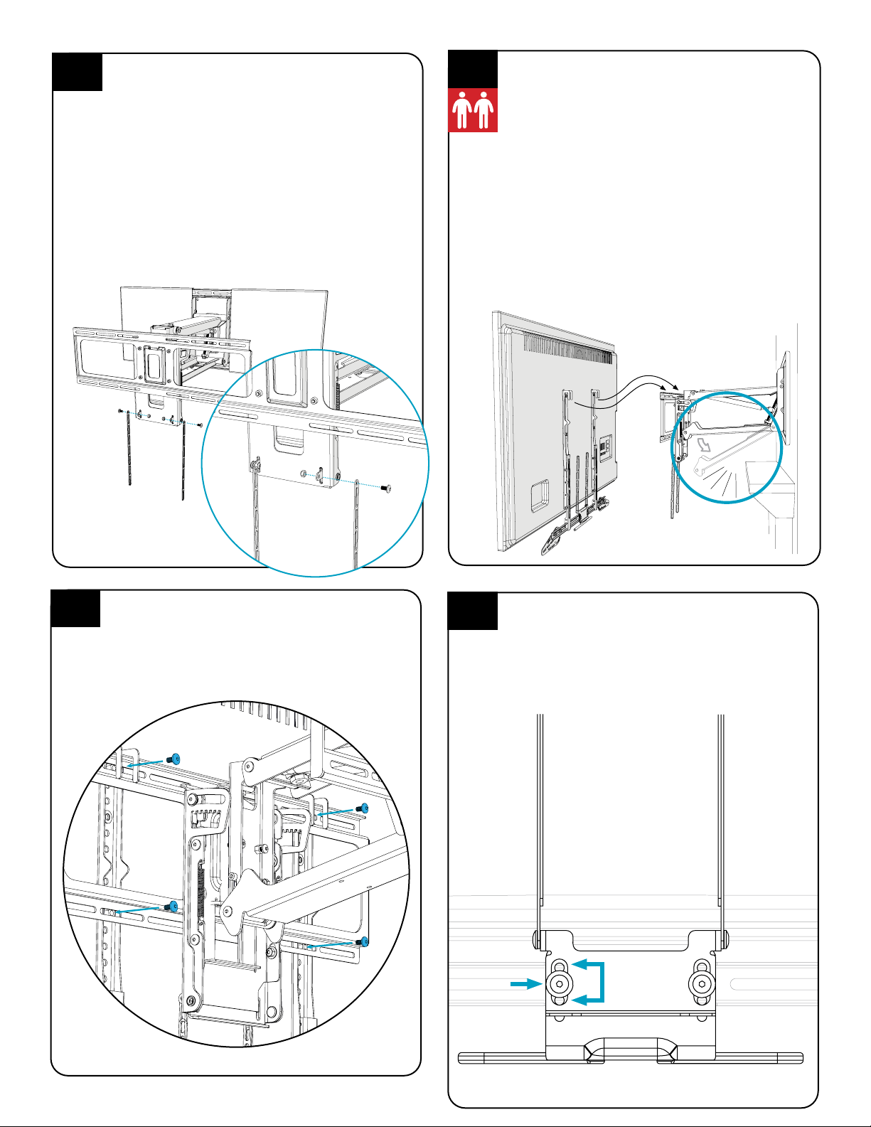
This step requires two people.
Carefully hang the Television onto the TV Brace making
sure that all four hooks on the Vertical Braces {31} engage
the TV Brace.
DO NOT allow the Television to drop far enough to cause
the Lifting Mechanism {35} to hit the mantle.
MantelMount comes pre-adjusted to reduce the
possibility of contacting the mantle, but you should
always be prepared to remove the television at this stage
to make the proper correction.
If the Lifting Mechanism {35} appears to be too close to
the mantle, remove television. Go to STEP 5.1 and make
an adjustment to the Bottom Stop position. Repeat this
process until the Lifting Mechanism is a safe distance from
the mantle when the TV is installed.
4.3
Install 4 Screws {15} through the TV Brace {33} and into
the Vertical Braces {31}.
4.4
When the lower Tilt Straps {54} are connected to the
upper Tilt Straps, the Slots in the Tilt Puller {65} must
be centered on its screws, as shown. Hold the Tilt Puller
centered until the Tilt Strap screws are tightened.
4.5
SLOTSCREW
4.2
Attaching top tilt linkage .
Attach two hanging Tilt Straps {54} to the front of the
Swivel Plate using two Screws {15} and two Nuts {23}.
Tighten screws as they will not be accessible after the
TV is mounted to the brace. Let the straps hang as we
will be attaching them to the rest of the tilt mechanism
after the television is attached to the MantelMount.
NOTE The tilt function does not work with the Recess
Box RB100, because the TV will be too close to the wall.
If you intend to use the RB100 Recess Box on with
your MantelMount installation DO NOT use parts
{65} or {54}. You can skip this step.

17
4.7
NOTE: Using the tilt function on your mount will require the use of both of your hands. You will use one hand to hold the handle
steady while pulling the Tilt Puller downward with the other hand. You will feel the locking mechanism disengage from the locked
position. You are now free to tilt your mount forward up to 10°. Once you achieve the desired tilt slowly release the Tilt Puller until
you feel it reengage the tilt lock mechanism.
Place one hand on the handle and
one hand pulling the Tilt Puller.
4.6
We can now use four Screws {15} and four Nuts {23}to attach the Tilt Straps to the hanging Tilt Straps we attached in step 4.4. When
attaching the hardware to the Tilt Straps attach them as close to the end of the straps as your installation allows.
Keep the slots centered.

MM720 Installation Instructions
18
4.10
Attach the electrical and signal cables to the TV.
Give each segment of the cables extra length so
that they are not stressed or kinked when the
mount moves.
Ensure that cables do not get pinched within the
Lifting Arm when the TV is raised.
Reference Only: This is one possible
conguration for the signal cables. Each
segment of the cables has extra length so that
the cables are not stressed or kinked when the
mount is moved.
{22}
4.9
{22}
Insert the two Cable Tie Anchors {22} into the two
holes in the Lower Arm of the Lifting Mechanism. Press
rmly until they are at.
Shown below is the easiest way to attach cables. Use
the included Cable Ties {24} to attach cables so they are
sideways to the Lower Arm, making a gentle loop.
Cables should be long enough to accommodate the
extension and swivel of MantelMount and do not get
caught between the lifting arm and the mounting
bracket. After check range of motion and cable
clearance tightening the Cable Ties.
4.8

STEP 5
Make Final
Adjustments
Tilt
Lifting
Force
Bottom
Stop
Side
Swivel
Stops Post-Leveling
Adjusting the Bottom
Stop Position:
Loosen the Locknuts and
adjust the Bottom Stop
screws to the desired
stopping position.
There is one screw on each
side of the Lifting Mechanism.
Make sure to balance both
sides evenly so the TV is level
in the DOWN position.
Tighten both Locknuts after
the adjustments are made.
5.1
Adjust the Side Swivel Stop
positions, if necessary.
To keep the TV from bumping the
mantel or wall, loosen the Locknuts
{23} and adjust the Swivel Stop
Screws to the desired stopping left
and right positions. Tighten both
Locknuts after the adjustments
are made.
If no swivel is desired, it may be
necessary to remove the Locknuts
and reattach them on the other
side of the Swivel Bracket so that
the Screws can be threaded out to
their maximum length.
5.2
MM720 Installation Instructions
20
Adjusting for Television weight.
With the Safety Latches Secured in place, use a socket wrench with an
extension to adjust the long bolt inside the Lifting Mechanism {35}.
Turn the bolt clockwise (AS SHOWN BELOW) to pull the Gas Springs
down and increase the lifting force for heavy TVs, or turn counter-
clockwise for lighter TVs. This adjustment can take several turns.
(Reference Step 4.3)
Adjust the bolt until the TV gently stays in the lowered position. Move
the TV up and down within the range below the Safety Latches. The TV
should almost stay up against the Safety Latches, but should be easily
lowered to the Bottom Stop.
5.3
Verify the proper Lifting Performance (Force)
MantelMount is designed to keep the TV securely in
the UP position while also allowing it to gently rest in
the DOWN position. Refer to diagram below.
If you need to make adjustments, reinsert the Safety
Latches and then repeat STEP 5.3.
For more information on rening Lifting
Performance, refer to “Mount Performance”
in the Troubleshooting Tips on page 26.
Neutral in the
MID positions
Weakest in the
DOWN/BOTTOM
position
Strongest in the
UP/TOP position
Safety Latches
Make Post-Leveling adjustments, if necessary.
Place a level on top of the TV while it’s in the UP position.
If it’s level, the installation is complete! If not, slightly
loosen all four Leveling Screws {15} and rotate the TV
until it’s level and then tighten all the Screws.
5.4
{15} x4
Table of contents
Other MantelMount TV Mount manuals

MantelMount
MantelMount MM750 User manual

MantelMount
MantelMount MM340 User manual

MantelMount
MantelMount MM340 Assembly instructions

MantelMount
MantelMount MM860 User manual

MantelMount
MantelMount MM540 User manual

MantelMount
MantelMount MM815 User manual

MantelMount
MantelMount MM440 User manual

MantelMount
MantelMount MM700 User manual

MantelMount
MantelMount MM710 User manual

MantelMount
MantelMount MM860 User manual


