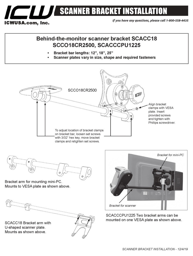
MantelMount MM340 User manual

Read this entire manual
before you begin.
Do not unpack
box contents
until verifying the
requirements listed
on page 2–3.
U.S. PAT. NO. 8,864,092
INSTALLATION INSTRUCTIONS
MM340
Standard
Pull Down
TV Mount
Contains important safety information – please save! MantelMount.com
If you need help, call 1.800.897.9755 ext.1
For missing/damaged parts or questions during installation,
please contact our Customer Support team at 1.800.897.9755 ext.1
or support@mantelmount.com. Customer satisfaction is our highest priority!

BEFORE INSTALLATION
3 Verify you have the required tools.
2
7/32"
4–5mm
10–14mm
AWL DRILL BIT PENCIL LEVEL STUD FINDER WRENCH SOCKET WRENCH POWER DRILL TAPE MEASURERALLEN WRENCHES
1Verify TV and mount space meet these criteria:
VESA
Width: 200-700mm
Height: 100-500mm
SCREEN SIZE
44" to 80"
(Diagonally)
2 Verify MantelMount will t the wall space.
VESA
Width: 200-700mm
Height: 100-500mm
44"– 80"
VESA COMPLIANT
Width: 200–600mm
Height: 200–600mm
WEIGHT CAPACITY
20 to 90 LBS.
(Including Sound Bar)
WOOD STUDS FOR MOUNTING
Studs Maximum 32" apart;
Wall Covering Maximum 5/8"
MANTEL DEPTH
18" MAXIMUM
VESA
Width: 200-700mm
Height: 100-500mm
MAX 90 LBS
18" MAX
WALL SPACE
HEIGHT
TV HEIGHT
MANTEL DEPTH
If Mantel Depth is: Required Vertical Space is:
Less than 9" TV height + 4"
9" – 11" TV height + 5"
11" – 14" TV height + 6"
14" – 18" TV height + 8"
A. Use the reference diagram (right) and chart (below) to write down the following
measurements (in inches):
Wall Space Height
:(Distance from mantel to ceiling/crown moulding.)
TV Height:
(Include sound bar height if placing below TV.)
Mantel Depth:
(Distance mantel extends away from the wall.)
Required Vertical Space:
(Calculation from chart below.)
B. If the Required Vertical Space is less than or equal to the Wall Space
Height, then MantelMount will t the wall space.
STUDS
MAX 32"
APART
MM340 Installation Instructions

{31} x2
Vertical
Brace
{30} x2
Vertical
Brace
Extender
{32} x1
Wall Plate
{33} x1
TV Brace
{35} x1
Lifting
Arm
{31} x2
Vertical
Brace
{30} x2
Vertical
Brace
Extender
{32} x1
Wall Plate
{33} x1
TV Brace
{35} x1
Lifting
Arm
{31} x2
Vertical
Brace
{30} x2
Vertical
Brace
Extender
{32} x1
Wall Plate
{33} x1
TV Brace
{35} x1
Lifting
Arm
BEFORE INSTALLATION
4 Verify all parts are included.
If any parts are
missing or damaged,
contact Customer
Support at
1-800-897-9755 ext.1
before installing.
3
{10} x4
M5-M6
{11} x8
M8
{12} x12
Spacer
{15} x16
M6x10
{18} x4
M6x40
{17} x4
Lag Bolt
{20} x1
Safety Bolt
{27} x1
Safety Nut M8
{23} x8
Locknut M6
{22}
x2
Anchor
{24} x4
Cable Ties
{14} x4
HEX M8x15
{53} x1
Center
Handle
{57} x2
Wall Cover
{31} x2
Vertical
Brace
{59} x2
Sound Bar
Wing
{30} x2
Brace
Extender
{32} x2
Wall Plate
{55} x1
Horizontal
Brace
{33} x1
TV Brace
{35} x1
Lifting
Mechanism
Black Parts for Mount
Silver Screws for back of TV
{02} x4
M5x30
{01} x4
M5x12
{03} x4
M5x40
{05} x4
M6x30
{04} x4
M6x16
{06} x4
M6x40
{08} x4
M8x25
{07} x4
M8x15
{09} x4
M8x45
{02} x4
M5x30
{01} x4
M5x12
{03} x4
M5x40
{05} x4
M6x30
{04} x4
M6x16
{06} x4
M6x40
{08} x4
M8x25
{07} x4
M8x15
{09} x4
M8x45
SILVER SCREWS FOR BACK OF TV
{10} x4
M5-M6
{11} x8
M8
{12} x12
Spacer
{15} x8
M6x10
{18} x4
M6x40
{17} x4
Lag Bolt
{20} x1
Safety Bolt
{27} x1
Safety Nut M8
{23} x4
Locknut M6
{22}
x2
Anchor
{24} x4
Cable Ties
{14} x4
HEX M8x15
{53} x1
Center
Handle
{57} x2
Wall Cover
{31} x2
Vertical
Brace
{59} x2
Sound Bar
Wing
{30} x2
Brace
Extender
{32} x2
Wall Plate
{55} x1
Horizontal
Brace
{33} x1
TV Brace
{35} x1
Lifting
Mechanism
Black Parts for Mount
Silver Screws for back of TV
{02} x4
M5x30
{01} x4
M5x12
{03} x4
M5x40
{05} x4
M6x30
{04} x4
M6x16
{06} x4
M6x40
{08} x4
M8x25
{07} x4
M8x15
{09} x4
M8x45
{10} x4
M5-M6
{11} x8
M8
{12} x12
Spacer
{15} x16
M6x10
{18} x4
M6x40
{17} x4
Lag Bolt
{20} x1
Safety Bolt
{27} x1
Safety Nut M8
{23} x8
Locknut M6
{22}
x2
Anchor
{24} x4
Cable Ties
{14} x4
HEX M8x15
{53} x1
Center
Handle
{57} x2
Wall Cover
{31} x2
Vertical
Brace
{59} x2
Sound Bar
Wing
{30} x2
Brace
Extender
{32} x2
Wall Plate
{55} x1
Horizontal
Brace
{33} x1
TV Brace
{35} x1
Lifting
Mechanism
Black Parts for Mount
Silver Screws for back of TV
{02} x4
M5x30
{01} x4
M5x12
{03} x4
M5x40
{05} x4
M6x30
{04} x4
M6x16
{06} x4
M6x40
{08} x4
M8x25
{07} x4
M8x15
{09} x4
M8x45
BLACK PARTS
FOR MOUNT
Thread patterns may vary.
{17} x4
Lag Bolt
{20} x1
Safety Bolt
{22} x2
Anchor
{24} x4
Cable Ties
{17} x4
Lag Bolt
{20} x1
Safety Bolt
{22} x2
Anchor
{24} x4
Cable Ties
{17} x4
Lag Bolt
{20} x1
Safety Bolt
{22} x2
Anchor
{24} x4
Cable Ties
{17} x4
Lag Bolt
{20} x1
Safety Bolt
{22}
x2
Anchor
{24} x4
Cable Ties
{17} x4
Lag Bolt
{20} x1
Safety Bolt
{22} x2
Anchor
{24} x4
Cable Ties
{10} x4
M5-M6
{11} x8
M8
{12} x12
Spacer
{10} x4
M5-M6
{11} x8
M8
{12} x12
Spacer
{10} x4
M5-M6
{11} x8
M8
{12} x12
Spacer
{10} x4
M5-M6
{11} x8
M8
{12} x12
Spacer
{15} x16
M6x10
{18} x4
M6x40
{17} x4
Lag Bolt
{20} x1
Safety Bolt
{27} x1
Safety Nut M8
{23} x8
Locknut M6
{22}
x2
Anchor
{24} x4
Cable Ties
{14} x4
HEX M8x15
{53} x1
Center
Handle
{57} x2
Wall Cover
{31} x2
Vertical
Brace
{59} x2
Sound Bar
Wing
{30} x2
Brace
Extender
{32} x2
Wall Plate
{55} x1
Horizontal
Brace
{33} x1
TV Brace
{35} x1
Lifting
Mechanism
Black Parts for Mount
Silver Screws for back of TV
{02} x4
M5x30
{01} x4
M5x12
{03} x4
M5x40
{05} x4
M6x30
{04} x4
M6x16
{06} x4
M6x40
{08} x4
M8x25
{07} x4
M8x15
{09} x4
M8x45

4
MM340 INSTALLATION STEPS
CAUTION / WARNING SPECIAL NOTE REQUIRES TWO PEOPLE
DO NOTHELPFUL INFORMATION
Symbols Used in this Manual
STEP 1 Attach Braces to TV
.....................................PAGE 5
STEP 2 Determine Wall Placement
..............................PAGE 7
STEP 3 Attach Mount to Wall
....................................PAGE 10
STEP 4 Attach TV to Mount
.....................................PAGE 12
STEP 5 Make Final Adjustments
.................................PAGE 14
This product is intended to
be installed by professional
contractors or persons
familiar with the tools and
methods required for this
installation.
If you are uncertain about
your ability to perform this
installation, please contact a
professional.
Keep children away from the
work area during installation.
This product contains small parts,
please keep out of reach from
children.
Do not let small children
pull on or hang from
MantelMount.
Only persons tall enough to
control the product all the
way to the top/raised position
should operate MantelMount.
Do not allow small children to
push MantelMount upward to
the top position. This will cause
the mount to slam against the
wall due to the upward force of
the springs.
WARNING WARNING CAUTION
Do not use this product for
purposes not specically
described in these
instructions.
MantelMount is not responsible
for damage or injury caused
by incorrect installation or
improper use.
CAUTION
Do not remove the gas
springs or any bolts that hold
the Lifting Arm together.
WARNING
Installation Tips & Videos: http://mantelmount.com/install-tips
Questions during installation? Contact Customer Support
Monday – Friday, 7am– 4pm PST
Two people required for parts of this installation.
MM340 Installation Instructions

STEP 1
Attach Braces
to TV
Select Screws and Spacers.
If Spacers {12} are required, choose one of these Screw
combinations shown with maximum Spacer usage.
1.3
{02}
{01} {10}
{10}
{10}
{10}
{11}
{11}
{11}
{12}
{12}
{10} {12}
{10} {12}
{12}
{12} {12}
{12} {12}
{12} {12}
{12}
{12}
{03}
{05}
{04}
{06}
{08}
{07}
{09}
M5
M6
M8
Test-t Brace components on back of TV.
Place TV screen-side down on a at, blanketed surface.
Lay out components to check assembly conguration.
1.1
Determine if TV has a at or irregular back.
An irregular back will require Spacers {12} and longer
Screws to ll spaces between the Vertical Brace {31} and
the TV. The Braces must be parallel to television screen.
1.2
Flat Back TV
Irregular Back TV {12}
{12}
{31}
{31}
Irregular Back TV
(Recessed Threads)
{31}
{31}
{30}
{31}
{30}
BACK
OF TV
Other manuals for MM340
4
Table of contents
Other MantelMount TV Mount manuals

MantelMount
MantelMount MM440 User manual

MantelMount
MantelMount MM860 User manual
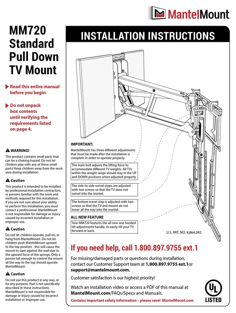
MantelMount
MantelMount MM720 User manual
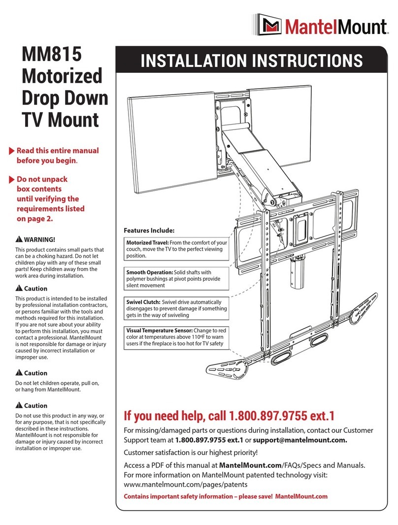
MantelMount
MantelMount MM815 User manual
MantelMount
MantelMount MM540 User manual
MantelMount
MantelMount MM710 User manual

MantelMount
MantelMount MM860 User manual

MantelMount
MantelMount MM750 User manual
MantelMount
MantelMount MM700 User manual
MantelMount
MantelMount MM340 Assembly instructions
