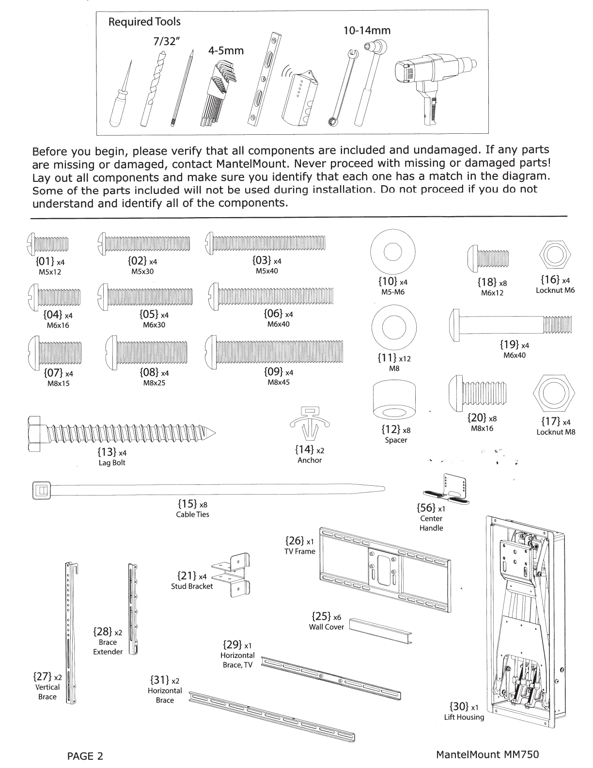
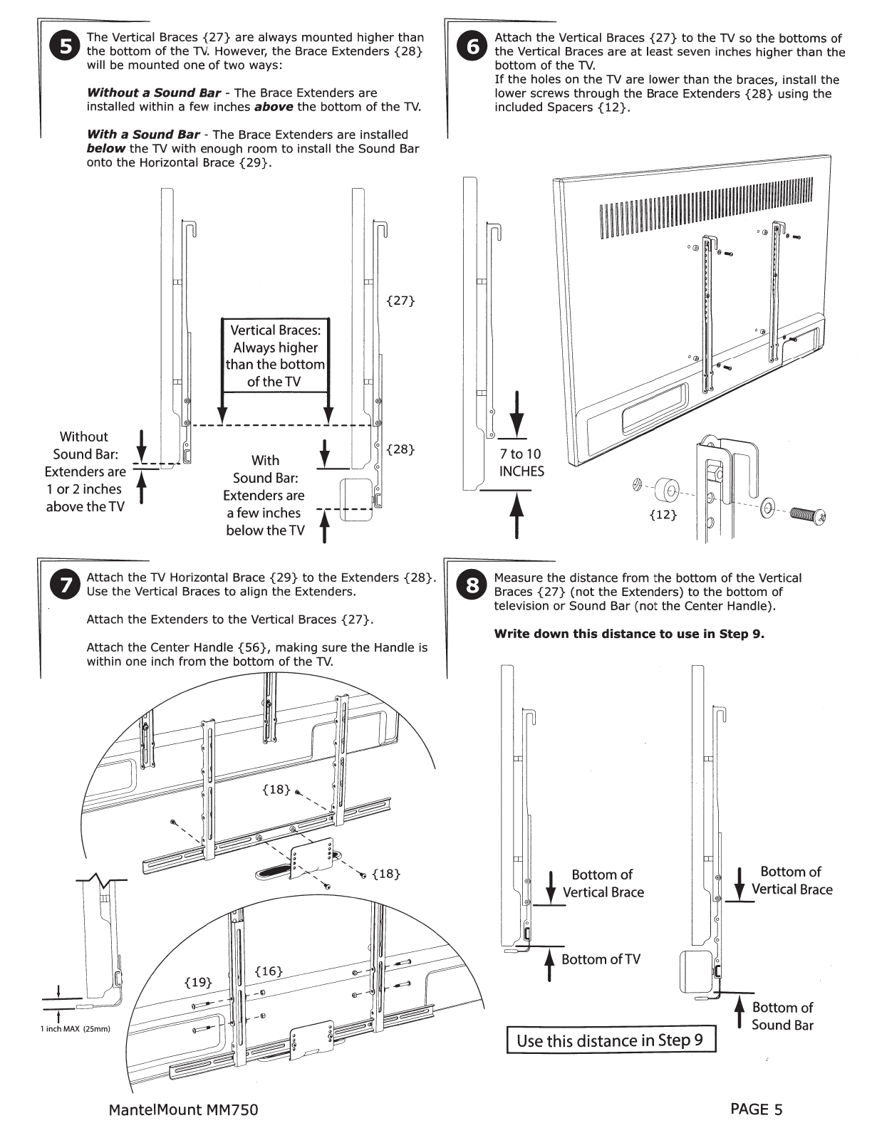
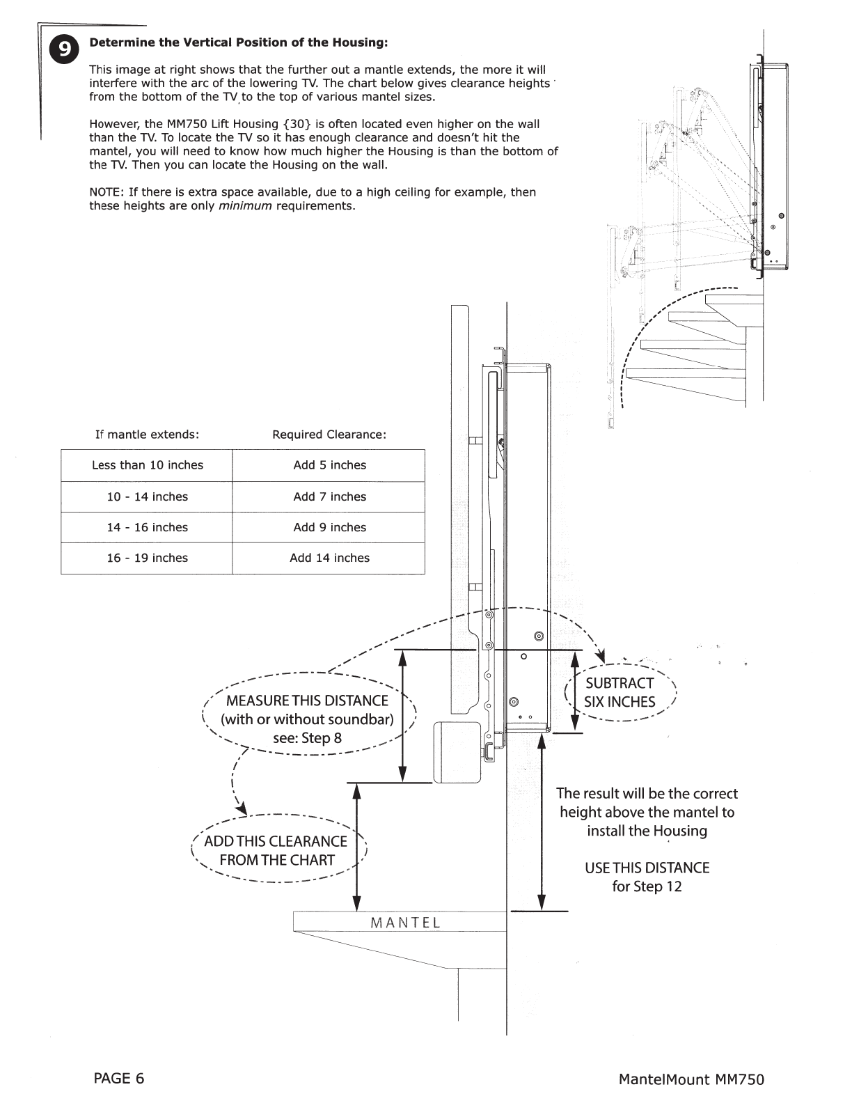
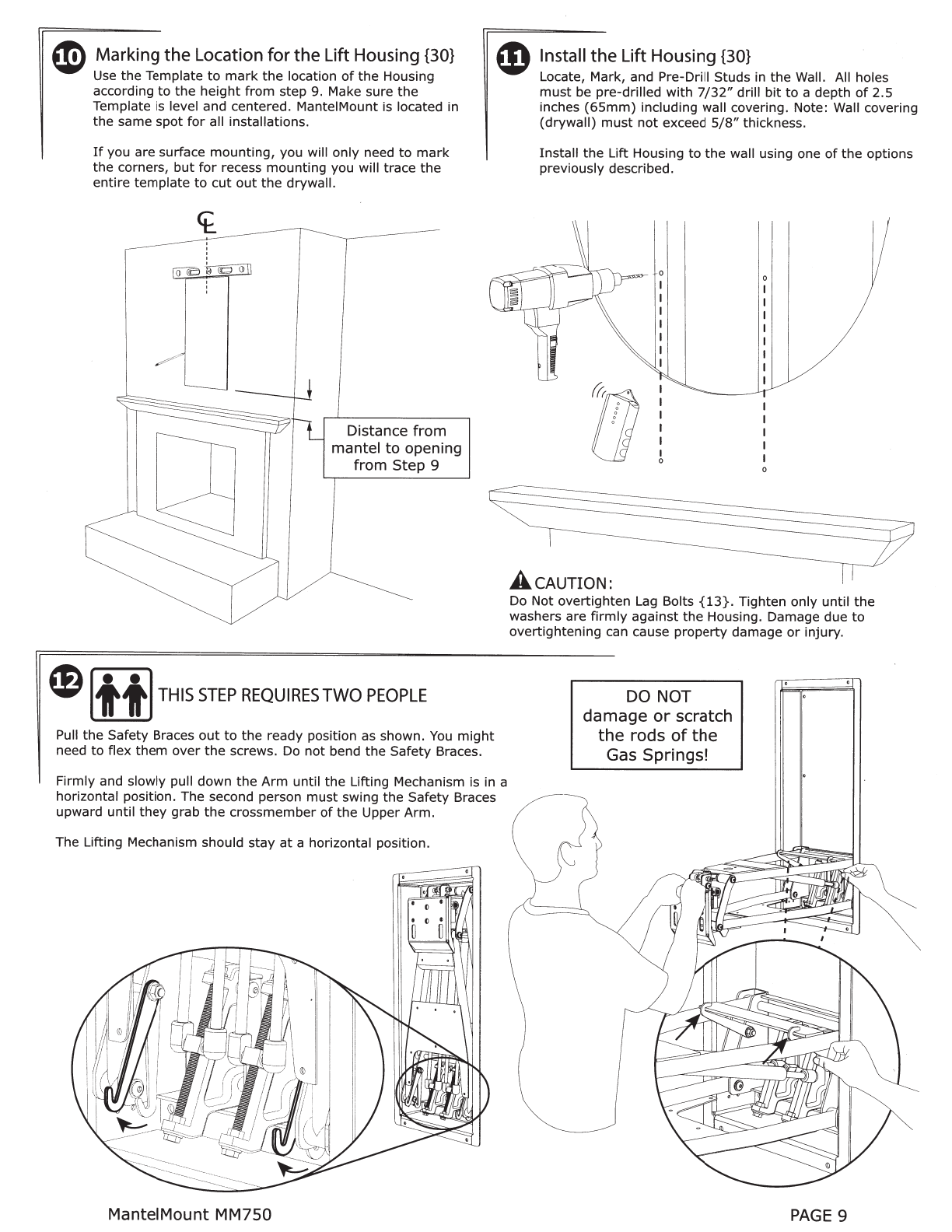
MantelMount MM750 User manual

[li]®
Mantel
Mount®
MM750
Installation
Instructions
IMPORTANT SAFETY INSTRUCTIONS -SAVE THESE INSTRUCTIONS
Please read
this
entire
manual before you begin.
Do
not
unpack
any
contents
until
you
verify
all requirements on
PAGE
3.
If
you have any questions,
visit
ManteiMount.com
or
call
(800)-897-9755.
A WARNING!
This product contains small parts
that
can be a
choking hazard.
Do
not
let
children play
with
any
of
these small parts! Keep children away
from
the
work
area during installation.
A WARNING!
Do
not
let
small children operate, pull on,
or
hang from
ManteiMount.
Do
not
operate ManteiMount when anyone is
near
or
behind the
mount.
ManteiMount is very strong and
can
result in crushing injuries.
A WARNING!
ManteiMount
must
be installed
to
a wall
or
structure
that
is able
to
hold five
times
the
combined
weight
of
all equipment.
If
you are unsure about
your
structure,
a contractor
must
evaluate
your
installation.
A WARNING!
Exceeding
the
weight
capacity can result in
serious personal
injury
or
damage
to
equipment!
The combined
weight
of
all components
must
not
exceed 110 lbs
(50
kg).
IMPORTANT:
ManteiMount has
three
different
adjustments
that
must
be made
after
the installation is
complete in
order
to
operate properly.
The side-to-side swivel stops are
adjusted
with
two
screws and
locknuts so
that
the
TV
does
not
swivel into the mantel.
Tilt
is removed with one screw
inside
the
swivel mechanism. The
TV
should always be vertically
parallel
to
the wall
The bottom travel stop is adjusted
with
two
screws and locknuts so
the
TV
and
mount
do
not
lower
all
the
way
into
the
mantel.
..
...
..
·
..
A
CAUTION:
This product is intended
to
be installed by
professional installation contractors,
or
persons
familiar
with
the
tools and methods required
for
this
installation.
If
you are
not
sure about
your
ability
to
perform this installation, you
must
contact a professional. ManteiMount is
not
responsible
for
damage
or
injury
caused
by
incorrect installation
or
improper
use.
A
CAUTION:
Do
not
use
this
product in any way,
or
for
any
purpose,
that
is
not
specifically described in these
instructions. ManteiMount is
not
responsible
for
damage
or
injury
caused by incorrect installation
or
improper use.
U.S. Pat. No.
8,864,092
ManteiMount MM750 www.ManteiMount.com
PAGE
1

Required
Tools
10-14mm
Before you begin, please
verify
that
all components are included and undamaged.
If
any
parts
are
missing
or
damaged,
contact
ManteiMount. Never proceed
with
missing
or
damaged parts!
Lay
out
all components and make sure you identify
that
each one has a match in
the
diagram.
Some
of
the
parts included will
not
be used during installation. Do
not
proceed
if
you do
not
understand and identify all
of
the
components.
-
{01}
x4
M5x12
~
{02}
x4
M5x30
a.~
{04}
x4
{OS}
x4
M6x16 M6x30
~~
{07}
x4
{08}
x4
M8x15 M8x25
{03}
x4
M5x40
M6x40
{09}
x4
M8x45
{14}
x2
Anchor
@
{1
0}
x4
MS-M6
@
{11}
x12
M8
{12}
x8
Spacer
{18}xs
M6x12
{19}
x4
M6x40
{16}
x4
LocknutM6
@180
{20}
x8
M8x16
{17}
x4
LocknutM8
,
,
~
,.,
~
~
--
------
--
--
--
--
-
~
~
{27}
x21
Vertical •
Bra
ce
,
{28}
x2
Bra
ce
Ex
tender
PAGE
2
{15}
x8
CableTies
{21}
x4
Stud Bracket
{31} x2
Horizontal
Brace
{29}
xl
Horizont
al
Br
ace,TV
{26}
xl
TV
Fr
a
me
{56}
xl
Center
Handle
{30}
xl
Lift
Hou
s
in
g
ManteiMount
MM750

Please
verify
that
your
installation
meets
all
of
these
CRITICAL
requirements:
A
c
E
ManteiMount is designed
for
use
only
with
decorative
fireplaces
that
are
not
the
primary
heat source
for
a
house. Temperature
at
the
front
edge
of
mantle should
never exceed
110°
F.
Mantle
must
not
extend
from
mounting
surface
more
than
19
inches
(22
inches
for
non-recessed
installations). ManteiMount can
not
extend past a mantel
larger
than
19 inches. Larger mantels will also reduce
the
amount
of
side-to
-side swivel.
19 inches
MAXIMUM
B
D
Wall
must
be WOOD STUD
FRAME
only. There
must
be
at
least 2 studs available
for
mounting. Wall covering
must
not
exceed
5/8
inch thick.
For
other
types
of
walls
or
other
types
of
installations
please visit
the
FAQ
section
at
www.ManteiMount.com.
TELEVISION REQUIREMENTS:
1.
Weight
must
be
below 110 pounds
(56
Kg).
2. Screen size larger
than
50 diagonal inches.
3. Mounting screw holes
are
VESA
compliant.
For non-vESA hole patterns, please
visit
the
FAQ section
at
www
.ManteiMount.com.
/
larger
than
50"
/
VESA
.
Width:200-
600mm
Height: 1
00-600mm
Note:
This is
not
an installation step,
only
a verification.
------
-
---------
--
,-------,
Do
not
use these dimensions
during
installation.
The space above
the
mantl
e
must
be
taller
than
the
TV.
The required space
depends on
how
far
out
th
e
mantle
extends. Refer
to
cha
rt
below and add this
additional
height
to
the
TV
height
to
determine
if
space is tall enough.
If
mantle
ext
ends: This is required space height:
Le
ss
than
10
inches TV
height
plus 6 inches
10 -
14
inches TV height plus 8 inches
14
-
16
inches TV
height
plus 10 inches
16
-
19
inches TV
height
plus 15 inches
ManteiMount MM750
.....
.r:::.
~
Q.l
.r:::.
Q.l
u
co
a.
Vl
-------
--
- -
-
-
~
'
Ma
ntle
_ :
Extends: '
I
PAGE 3

0 Use a Vertical Brace
{27}
to
determine
if
your
television
is a
flat
back
or
an
irregular
back.
An
irregular
back will
require spacers and
longer
screws
to
fill any spaces
between
the
Vertical Brace and
the
TV.
The Braces
must
be parallel
to
your
television screen.
Flat Back Irregular Back Irregular Back
(Recessed
Threads)
ePossible Screw Combinations shown
with
maximum
spacer usage
(if
spacers are required).
C®\@)©D·
~{02}
v {12} {12}
{1
0}
(~JQ\\@)}@)
...
~--·---v
\2U
{12} {12}
{03}
{1
0} {12}
(~
{11}
PAGE
4
(~@}
~{OS}
{12}
{10}
(clf@}
10
{12}
{11}
®
-f©J@)@)···
-{12} {12}
{12}
{11}
6 Choose
the
correct screw
diameter
and length
for
the
TV.
V Hand-thread screw combination into
the
TV
to
ensure
there
is
adequate thread
engagement
without
hitting
the
bottom
of
tt:lreaded insert.
Use
only
minimum
amount
of
spacers
(if
required).
Must leave a gap
in
threaded
TV
.
~
msert
7-1?
~hreads-1
m1mmum
engagement
A CAUTION:
Do
Not use screws
that
are too long
for
the
threaded
inserts
of
Television. This can
damage
internal components.
0 IMPORTANT INFORMATION: The Vertical Braces
{27}
are
a fixed distance
higher
than
the
bottom
of
the
Lift Housing
Frame
{30}.
This relationship can be used
to
calculate
most
mounting
situations such as centering
the
TV in an
alcove
or
mounting
the
TV
at
a specific
height
on
the
wall.
If
you measure
the
distance
from
the
bottom
of
your
TV
(or
Sound Bar)
to
the
bottom
of
the
Vertical Braces
{27}
(see:
page 5) you will automaticatly
know
·
the
,
distance
from
the
bottom
of
your
TV
to
the
bottom
of
the
Lift Housing
{30}.
You
can use this
information
to
install
the
Lift Housing on
the
wall in
order
to
locate
your
TV
to
any specific
height
you desire.
Example:
If
the
Vertical Braces are
attached
10
inches
from
the
bottom
of
the
TV,
then
the
bottom
of
the
cutout
opening
should be 4 inches
higher
than where you
want
the
bottom
edge
of
the TV on
the
wall
(10"-
6"
=
4").
,
If
you are installing above a
mantel,
then
your
installation
must
still have
the
additional clearance
for
downward
motion
stated in
the
chart
in Step 9.
7.5
INCHES
to
Flange edge
6
INCHES
to
housing
)
\~
'\
or
cutout
,,
-----
-~~;;}!
ManteiMount MM750

ft
The Vertical Braces
{27}
are always mounted
higher
than
V the
bottom
of
the
TV.
However,
the
Brace Extenders
{28}
will be mounted one
of
two
ways:
Without
a
Sound
Bar
-The Brace Extenders are
installed
within
a few inches
above
the
bottom
of
the
TV.
With
a
Sound
Bar
-The Brace Extenders are installed
below
the
TV
with
enough
room
to
install
the
Sound Bar
onto
the
Horizontal Brace
{29}.
Vertical
Braces:
Always higher
than
the
bottom
of
the
TV
-----------
--
- ®
{27}
Without 1
Sound
Bar:
J.
_
Extenders are -t
1
or
2 inches
abovetheTV
0
{28}
With
Sound
Bar:
Extenders are
a
few
inches
-t-
belowtheTV
A Attach
the
TV Horizontal Brace
{29}
to
the
Extenders
{28}.
V
Use
the
Vertical Braces
to
align
the
Extenders.
-t-
Attach
the
Extenders
to
the
Vertical Braces
{27}.
Attach
the
Center Handle
{56},
making sure
the
Handle is
within one inch from
the
bottom
of
the
TV.
"17
{18}
1 inch
MA
X (
2S
mm)
ManteiMount MM750
A Attach
the
Vertical Braces
{27}
to
the
TV so
the
bottoms
of
V
the
Vertical Braces are
at
least seven inches
higher
than
the
bottom
of
the
TV.
If
the
holes on
the
TV are
lower
than the braces, install
the
lower screws
through
the
Brace Extenders
{28}
using
the
included Spacers
{12}.
!IIIII
I
lll
lllllllllllllll
ll
llllllllllll!~""
11
~
1
~m
1
7
to
10
INCHES
t
'@
@--®---
{12}
---
-@-
-fill@
A Measure
the
distance
from
the
bottom
of
the
Vertical
W Braces
{27}
(not
the
Extenders)
to
the
bottom
of
television
or
Sound Bar
(not
the
Center Handle).
Write
down
this
distance
to
use
in
Step
9.
.,
1.Bottom
of
"'
_!_Vertical
Brace
tBottom
ofTV
Use
this distance in Step 9
.,
1.Bottom
of
_I_Vertical
Brace
PAGE 5

Determine
the
Vertical
Position
of
the
Housing:
This image
at
right
shows
that
the
further
out
a
mantle
extends,
the
more
it
will
interfere
with
the
arc
of
the
lowering
TV.
The
chart
below gives clearance
heights·
from
the
bottom
of
the
TV.
to
the
top
of
various mantel sizes.
However,
the
MM750 Lift Housing
{30}
is
often located even
higher
on
the
wall
than
the
TV.
To
locate
the
TV so
it
has enough clearance and
doesn't
hit
the
mantel, you will need
to
know
how
much
higher
the
Housing is
than
the
bottom
of
the
TV.
Then you can locate
the
Housing on
the
wall.
NOTE:
If
there
is extra space available, due
to
a high ceiling
for
example, then
these heights are only
minimum
requirements.
If
mantle
extends:
Less than
10
inches
10
-
14
inches
14
-
16
inches
16-
19
inches
Required Clearance:
Add 5 inches
Add 7 inches
Add 9 inches
Add 14 inches
MEASURE
THIS
DISTANCE
1\
, (with
or
without
soundbar) /
'·-...
see:
Step 8
_..,.
...-'
,/
..
-
...
-
..
-
..
---
..
-
..
~
..
---
..
®
0
®
.0
..,
'
[""
=
.
.....
.,
.
' :'·
(t
~
../ .
..
--
--
·
-~-
...........
SUBTRACT
\
.
SIX
INCHES
' I
/
-.
-~-
..
-
"'
I
l
'
\
The
result will be
the
correct
hei
ght
above the mantel
to
install the
H<;>using
~-
---
-
-
,.,..
..
-
..
-...
..
....
.....
/
ADD
THIS
CLEARANCE
-i',
USE
THIS
DISTANCE
,.
for Step 12
\,_
FROM
THE
CHART
/
.....
__.
..
._
..
_ _
___
..
I
MAN
TEL
~-
--
PAGE 6
Mant
eiMount MM750

Installation Options: Surface Mount
SURFACE
MOUNT (non-recessed) installation using Horizontal Braces
{31}
to
attach
to
existing wall studs, on
top
of
existing drywall.
The Horizontal Braces can reach studs
that
are up
to
34 inches
(875mm)
apart. They attach flush
to
the
back
of
the
Lift Housing
{30}.
UlmO
{20} {17}
QJIIIIIIIIIII\11\111\1'>
@
{13} {11}
\
SURFACE
MOUNT (non-recessed) installation
onto
stone
or
concrete walls using
the
six holes in
the
back
of
the Lift Housing
{30}.
The wall
must
be solid stone
or
concrete
that
can hold
five
times
the
weight
of
all combined equipment. This
surface
must
not
be a facade
or
non-structural
material.
Use concrete anchors
(not
included)
to
attach
the
Lift
Housing
to
the
surface.
Concrete Anchoring Hardware
Not
Included
Installation Options: Recessed using Horizontal Braces
{31}
RECESSED
installation using
the
Horizontal Braces
{31}
to
attach
to
existing wall studs:
The Horizontal Braces attach
to
the
flange on
the
front
of
the
Lift Housing
{30}.
The Braces can be located
off-center
to
the Housing,
if
needed,
to
reach
the
nearest stud.
Use
the
included Template
to
mark
the
location
to
cut
the
drywall.
This installation is
easiest when
there
is
no
center
stud
that
needs
to
be
cut
to
make room.
Paintable Wall Covers
{25}
can be snapped onto
the
Horizontal Braces.
{31}
Ql8MO
{20} {17}
QJIIIIII\1111111111111"
> @
{13} {11}
ManteiMount MM750
PAGE
7

Installation
Options: Recessed using
2x4
Stud Brackets
{21}
MM750 includes brackets
that
make
it
easier
to
install horizontal
pieces
of
2x4 bracing inside
the
wall. This is because all
of
the
attachment
holes in
the
Brackets can be reached
for
drilling
and
screwing
simply
by
reaching
through
the
opening
that
is
cut
for
the
Lift
Housing
{30},
see FIG.
A.
When wall studs
are
far
apart,
or
when
a
center
stud needs
to
be
cut,
or
when
the
cleanest look is desired, sections
of
horizontal
2x4
can be installed
through
the
cutout.
They provide a solid
structure
for
the
mount
without
the
need
for
the
Horizontal
Braces
{31}.
The
mount
is attached
with
Lag Bolts
through
the
holes in
the
front
flange
of
the
Lift
Housing
{30}
.
The
Stud
Brackets can be attached
with
lag bolts,
or
bolts
with
nuts
and washers. The hardware
to
attach
the
Stud Brackets is
not
included.
FIG. A
(view
from
inside
the
wall) FIG. B
~11111111111111111111'
>
{13}
@
{11}
II
II
II
II
Drywall
Not
Shown
(view
from
inside
the
wall)
I
I
I
I
'
\
Cutting a
Center
Stud:
When
cutting
a
center
stud, measure
1.5"
above and below
the
template
mark
before
the
opening is
cut
out.
The
drywall
will hold
the
stud
in place while
it
is
cut.
Plunge
cut
through
the
stud
at
both locations and
attach
the
cut
ends
to
the
cross bracing when
they
are installed, see FIG.
C.
{21}
Stud
Bracket
PAGE
8
Note:
If
the
Bracket
is
near
the
cutout
opening,
make
sure
to
orient
the
attaching
hardware
away
from
the
opening so
they
do
not
interfere
with
the
Lift
Housing
{30}.
This
hardware
is
attached before
the
braces are
installed
into
the
wall, see FIG.
B.
...
.
,.
·..
·'• '
FIG. C
(view
facing
the
wall)
IL
LS"~
I
II
.
II
I; -
~:
:tl---:.
=:=;:~
~-=1
1
I I
I I
I I
I I
I I
I I
I I
I I
ManteiMount
MM750

~
Marking
the
Location
for
the
Lift Housing {30}
Use
the
Template
to
mark
the
location
of
the
Housing
according
to
the
height
from
step
9. Make sure
the
Template is level and centered. ManteiMount is located in
the same
spot
for
all installations.
If
you are surface
mounting,
you will only need
to
mark
the corners,
but
for
recess
mounting
you will trace
the
entire
template
to
cut
out
the
drywall.
Distance
from
mantel
to
opening
from
Step 9
~
Itt]
THIS
STEP
REQUIRES
TWO
PEOPLE
Pull
the
Safety Braces
out
to
the
ready position as shown.
You
might
need
to
flex
them
over
the
screws. Do
not
bend
the
Safety Braces.
Firmly and slowly pull down
the
Arm
until
the Lifting Mechanism is in a
horizontal position. The second person
must
swing
the
Safety Braces
upward until
they
grab
the
cross
member
of
th
e Upper
Arm
.
The Lifting Mechanism should
stay
at
a horizontal posi
tion.
ManteiMount MM750
Install
the
Lift Housing {30}
Locate, Mark, and Pre-Drill Studs in
the
Wall. All holes
must
be pre-drilled
with
7
/32"
drill
bit
to
a depth
of
2.5
inches
(65mm)
including wall covering. Note: Wall covering
(drywall)
must
not
exceed
5/8"
thickness.
Install
the
Lift Housing
to
the
wall using one
of
the
options
previously described.
0
.A.
cAUTION:
Do
Not
overtighten Lag Bolts
{13}.
Tighten only
until
the
washers are
firmly
against
the
Housing. Damage due
to
overtightening can cause property damage
or
injury.
DO
NOT
damage
or
scratch
the
rods
of
the
Gas Springs!
PAGE 9

eAwARNING:
DO
NOT
put
hands into Lifting Mechanism while operating
the
mount. Severe
Injury
can
occur
due
to
pinching
or
crushing. Always use the Safety Braces when working
near
or
inside ManteiMount.
ONLY
WITH
SAFETY BRACES
IN
PLACE!
~
Iii
I
THIS
STEP
REQUIRES
TWO
PEOPLE
Carefully hang
the
Television
onto
the
TV Frame
making
sure
that
both hooks on
the
Vertical
Braces
{27}
engage
the
TV Frame.
DO
NOT
allow
the
Television
to
drop
far
enough
to
cause
the
Lifting Mechanism
to
hit
the
mantle.
ManteiMount comes pre-adjusted
to
reduce
the
possibility
of
contacting
the
mantle,
but
you
should always be prepared
to
remove
the
television
at
this
stage
to
make
the
proper
correction.
If
the
Lift Housing
{30}
appears
to
be
too
close
to
the
mantle, remove television. Go
to
STEP
17
and make an
adjustment
to
the
Bottom
Stop
position. Repeat this process
until
the
Lifting
Mechanism is a safe distance
from
the
mantle
when the TV is installed.
Some
older
TVs are
not
weight balanced.
If
the
TV is much heavier on one side, slide
the
TV
slightly
sideways
to
balance and level
the
TV.
Attach with 4 Screws
{18}.
PAGE
10
Install
the
TV Frame
{26}
using 4 Screws
{20}
and
Washers
{11}.
These screws can also be used
to
fine
tune
level
th~
TV.
Always
remember
to
tighten.
a.
@
{20} {11}
l)t
@
l)t
-@
-----------
,
Jinc
hes
h
MAX
\J'
ManteiMount
MM750

Adjusting
for
Television
weight:
With Safety Braces in place, use a socket
wrench with an extension
to
adjust
the
long bolts inside
the
Lift Housing
{30}.
Take
turns adjusting each side so
they
stay relatively even with each other.
Turn
the
bolts clockwise (AS
SHOWN
BELOW)
to
pull
the
Gas Springs down and
increase
the
lifting force
for
heavy TVs,
or
turn counter-clockwise
for
lighter
TVs.
This
adjustment
can take several turns. Reference
the
sticker scale on each side
for
the
weight
of
the
TV.
Each
scale represents
the
TOTAL
WEIGHT
of
the
TV.
Adjust
the
bolt until
the
TV
gently stays
in
the lowered position. When
the
mount
moves with a neutral feel within
the
Safety Braces, un-latch
the
Safety Braces and
check the
mount
operation
throughout
the
full range
of
motion.
(TV and some components are
not
shown
in
these images
for
clarity.)
Safety
Braces
Locked
~
Align the
TOP
of
the block
with the desired weight
Verify
the
proper
lifting
performance:
Adjust
each
side
evenly
Clockwise for heavyTVs
ManteiMount MM750
ManteiMount lifting force
is
designed
to
keep
the
TV
securely in
the
up position while also allowing
the TV
to
gently
rest
in
the
down position. See
the
diagram below
for
the
correct lifting adjustment.
Neutral in the
MID positions
Strongest in the
------.
UP
position
Weakest
in
the
Bottom position
PAGE
11

Adjusting the Hard Stops
for
Range
of
Motion:
Adjusting
the
Bottom
Stop
Position:
Loosen
the
Locknuts and 'adjust
the Bottom Stop screws
to
the
desired stopping position.
There are
two
screws underneath
the Lifting Mechanism. Turn these
screws inward until
they
tighten
at
the desired lower position.
Tighten both locknuts
after
the
adjustments are made.
..
~
~q"'ingM~w~nted
Tilt:
The>
T:V
:
s!!la.utd
,be fairly vertical in
the
up position and
parallel
to
the
wall.
If
the
TV
is tilted slightly downward,
back
out
the adjustment screw slightly as shown.
Tighten the locknut after
the
adjustment
is made.
PAGE12
II!\
Adjusting
the
Side
Swivel
Stop
~
Positions:
Loosen
the
Locknuts and adjust
the
Swivel Stop screws
to
the desired
stopping positions, both
left
and
right. ·
Tighten both locknuts
after
the
adjustments are made.
Note:
If
no swivel is desired,
it
may
be
necessary
to
remove the locknuts
and re-attach them on the other side
of
the
Swivel Bracket so
that
the
Screws can
be
threaded
out
to
their
maximum length.
e
Attaching
Cables:
If
cables are attached using the Anchors
{14},
ensure
that
cables are
not
near the pinchingcarea
if.-
IV
~
Frame
and
swivel portion
of
the
moUQt.,.l(~ables
ar~
Q~;r
/
f!e
swivel,
loop them away from
the
pinch area securely. ·
I
Keep all Cables }
below pinch area
<,
I
\
Anchor
{14}
Cable
Ties
{15}
0
0
ManteiMount
MM750
0
0

~
Reference Only: This is one possible configuration
for
the
signal cables.
Each
segment
of
the
cables
W
has extra length so
that
the
cables are
not
stressed
or
kinked when
the
mount
is moved.
Ensure
that
cables do
not
get
pinched between brackets when
the
mount
is raised.
A
CAUTION:
Never release
the
handle before
it
is fully upright.
ManteiMount is strongest in
the
top position, and
allowing
it
to
slam closed can damage televisions.
Always control
the
lifting process.
/
"JJ
·
'=
~
:
~
·
,.;,
..
A
CAUTION:
Never allow small children
to
play around
or
operate ManteiMount. Property damage
or
personal
injury
can occur.
ManteiMount MM750
PAGE
13

;g
G)
m
.......
.:::..
3:
OJ
::J
......
(!)
3:
0
c
::J
......
3:
3:
-..,J
U1
0
r
]
~
s
'i
..
-
~
'/
..
ol
~
.,
ol
~
..
~
~~
..
..
(
2_7
\
·
--
\
.....
_,
__
..
.!
r1
6'\
\ -
__;
r
~
,
I
i
19
"
~
j
~
<iJ
•
'<;,
(s
7)
r5
6)
~
~
~
·
(
l9
J '
·
~
(
18
;
'-
-
~
~
,
__
/
r;.~~
~
-
~
'\
~
\ 1,'
i ...
8
..
1
..
I
..
@
~
..
,~
~)
~
,
,,
[
f.:;\
44
'
\0
~
"~
_(
43
)
'·
CQ
--~
@
(
2
0----
-
~
G
'-..
I
D--.._
".
r
4
~
-
-
Ys
1
1
~
\::_/
\
~
/..' '
i
39
)
<e
@
~
~
-
®0J
<e
• '
c:::n'
@
tl
0
@
@
r -
--....
,
'
11
:
@
-----
··-",
__
./
o
G
--
-
--
~~
~
~
l
~
~
co
~
/
~,
/
11
\
~
-
•43 !
'
\_
')
~
-"'\..:/
CQ
@
G
0
~
)-
~
~
-,
<=
-J
45
\
,
..o
I
'(:J
0
_!
)
--
@
_,.---,
\
2
~
!J D
(4
2\
(()
_.
--
'-...
~
Y D
(3-7\
__j
co
@
G
~
---
-
~
-
---
\
-
\2
?J
:
s
~
)
(3
2)
~
~
\ , 88
"'
=:,(
_.
(
2
~
2
(
33
·,, \ )
\:::
J f
.-
--
,
(
52
)(""'
k .
i
11
\
f[A
4s
)
0~
iJ
(32
)
-
~
~
~
-
p
::
(.,
"'
~
0 3)
___
_...
"'
«(
l@:tQ~
@@
)
--
-\
_1
7/@
(
?~
)
r!l
~
65
'--
---
<e
G
<e
(_vl
/1
_
'
55
r·
--
.,__
\.:
j
~
1
34
@
\,
'
~
I_, .
~
o
)
"-.
,
./
(3
g\
\:::
.
'J
co
(@
@
G
:"
.,
..-
--
---
--\
20
\
(!)-
---
--~
-
---
/
@)
,, \ r
(4-
-6
·
\..-
-50 \
-
_.
~
>
i
I ' '
i
-
'/
.
CO
1 I
/-
-:-;'
@
I
\42 ! @
\
._.__...,
)
uG
:1
8
V
i
.
!
.
0t
~
1~
©~
~
l
r
&
i\W
~W,
-
l
;,
I ,,, , ,
~..;\::';Lru_
r
Additional Installation
Parts
!
s9
!
\
~
__
/,
,
'.
·
01
TITITITI
04
lJ
ITIT
IT
07
IJ
TITITI
10
11
12
13
14
@
@@
~
~
Jill
+~
02
~
~~~
OS
UTI
U
TI
0~
U
TI
U
TI
@
@@
u u
~~
03
~~~~
06
~~
m
o~
~ ~ ~
u
@
@@
uu
..
@
@@
u u
II
i
:_
s.~
l
~
~
~
~
u
l
~
~
~~
~~u
w~
15
~

~
QJ
::J
,..,.
(!)
~
0
c
::J
,..,.
~
~
-...J
lJ1
0
:g
.
G1
m
~
lJ1
"'
"'
j
~
!:l
F
fTE~No.
2 I
I
f
---
3
I 4
5
6
7
8
1----
-
---
-
·-··
.
I 9 '
i
10
I
i
11
j
- ·- -
12
13
14
f---------~--
-
15
f------
--
----
16
17
f------
-·
18
I
I
19
I
20
I
21
22
23
24
25
26
27
28
29
30
PART
NU~ER
'
·
.,.,
,.
12189
.-_
12190
12191
12193
12194
12195
12197
12198
12199
12166
14126
12122
-
14137
14110
12162
12183
12187
·-
12178
12255
12176
15023
12186
21088
21090
21140
21050
14038
14056
14060
-
"----1---
,/
21115
-.
-
----
- - --
DESCRIPTION
QTY
.
-
M5x12 4
-- ·-
M5x30 4
M5x40 4
M6x16 4
M6x30 4
M6x40 4
M8x
15
4
M8x25 4
M8x45 4
-
--
-
Washer
M6
4
'
Washer
M8
x2
36
-1
- ·
Spacer
s-
-I
I
Lag
Bolt
M8
x
60
4 I
Cable
Tie
Anchor
I
I 4
Cable
Tie
8
-~----~
Locknut
M6
6
I
Locknut
M8
8
--
t---
-
--
Round
Screw
M6
x
12
8
Round
Screw
M6
x
40
4
Round
Screw
M8
x
16
34
Stud
Bracket
4
NutM8 7
Socket
Cap
Screw
M8
x
25
3
Socket
Cap
Screw
M8
x
40
2
Wall
Cover
6
. lf'Frame,
Welded
1
Vertical
Brace
2
Brace
Extender
2
--
TV
Horizontal
Brace
1
Recess
Frame,
750,
Welded
1
ITEM
NO.
'
PART
NUMBER
DESCRIPTION
QTY
.
31
21039
Horizontal
Brace
2
32
14115
Sliding
Spring
Mount 4
33
12247
Disk
Spring
Washer
M8
4
34
21085
Adjustment
Block
2
35
21180
Hex
Bolt
M8
x
160
2
36
12160
Gas
Spring
4
37
21110
Upper
Arm,
750,
Welded
1
38
21081
Lower
Arm
,
Welded
1
39
21060
Swivel
1
-
40
21045
Tilt
Bracket,
Welded
1
41
21044
Axle,
750
1
42
21119
Bushing
4 I
I
43
21037
Axle
2
44
21121
Bushing
4
45
21092
Washer
M8
x3x
24
2
t--
·
46
21035
Axle
~
-
47
21054
Top
Pivot
1 I
--
48
21041
Connector
Brace
2
I
I
49
21063
Bottom Pivot 1
so
21178
Round
Screw
M6
x
15
2
51
21163
Set
Screw
M5
x
15
2
52
21144
Round
Sc
r
ew
M8
x
60
2
53
21135
Safety
Brace
2
54
21211
Warning
Sticker
1
55
21206
Adjustment
Sticker
2
56
14062
Center
Handle
1
57
12222
Handle
Rubber
~
Temp.
Change
2
58
21190
CardboardT~mptate
735
x
335mm
-I' 1
59
MM750M
lnstruci~Q~l
~
ual
· ..
~.;:
1"' . 1
·.
•. .. \ , ·
:
;-~
:':
"
...
o'-c ·._._.
_.
,, •;'\ .
..
.

Customer Service:
(800)-897-9755
www.ManteiMount.com
30.5
Maximum
Drop
@
@
0
28
.75
1+--1--
-
3.
6
Recess
Depth
[1+-
+tt---
20
.5
Max
---~
Recessed Clearance
@
0
[1
+----
17.0
Min
Recessed Clearance
Exclusive Mante!Mount Features!
Auto-Straighten
in
g:
Flattens
the
TV
as
it
is
rai
se
d
toth
e
upp
er
po
si
tion
to
prevent rotation
into
thewall
Safe
ty
Bra
ces:
Hold
th
e
mount
sa
fe
ly
in
th
e
down
position
to
work
behind
the
TV
during
installation
SmoothOperation:
S
olid
shafts
with
polymer
bushings
at
each
pivot
point
provide sile
nt
mov
ement
Temperature-Sensing Handl
es:
Cha
nge
to
red colorat
temperaturesabove
11
0°F
to
warn
u
se
rs
if
the
fir
eplace
is
too
hot
for
TVsafety
-
---------
35.4
---------~
1
+-------
27.8
-------~llol
'
~c::=:=::::::Ja::::::==::::>~c::==:=o~c:::::::==::)~
0 0
==
==
.o=
c=m
= =
0
@[]@
0
0 0
0 0
0
@
@
@
0
0
§ §
0
0
I \
0
0 0
0 0
= =
<JI:J=
==
==
31.5
I
*-
______
725mm
------+1
_1
Sound
bar
2.
' -
/
,..
Full ManufacturerWarranty:
Mantel
Mount
will
replace
or
repair any
product
or
part
that
proves defective due
to
improp
er workmanship
or
material during
the
warranty period.
Visitwww.ManteiMount.c
om
for details.
This Installation Manual
is
available
for
download
as
a
PDF
document
at www.ManteiMount.com. The
PDF
version can be
used
to
see
larger images
or
to
zoom in for much greaterdetail.
PAGE
16
U.S. Pat. No.
8,864,092
01Jan2018
MantleMount
MM750
Other MantelMount TV Mount manuals

MantelMount
MantelMount MM700 User manual

MantelMount
MantelMount MM340 Assembly instructions

MantelMount
MantelMount MM540 User manual

MantelMount
MantelMount MM860 User manual

MantelMount
MantelMount MM710 User manual

MantelMount
MantelMount MM340 User manual

MantelMount
MantelMount MM860 User manual

MantelMount
MantelMount MM440 User manual

MantelMount
MantelMount MM720 User manual

MantelMount
MantelMount MM815 User manual