MM710 Installation Instructions 27
CONTINUED FROM PREVIOUS PAGE
TV is level in the UP
position, but unleveled in the
DOWN position.
TV is level in the DOWN
position, but unleveled
in the UP position.
MOUNT PERFORMANCE
TV LEVELING
ISSUE
ISSUE
SOLUTION (May require some trial and error to reach optimal performance.)
POSSIBLE CAUSE HOW TO CHECK SOLUTION
TV is tilting forward
when in the UP position.
This is generally an indication that the Lifting Force is not set tight enough in the UP position (see Step 5.1).
Slightly turn the Tension Bolt clockwise and try again. The goal is to adjust the Lifting Force just enough for the TV
to no longer tilt in the UP position. Be careful not to set the Lifting Force too tightly in UP position or the TV may
not fully lower to the optimal viewing position.
The mantel, ceiling or
oor may not be level.
Wall Plates aren’t level.
The Bottom Stops
aren’t evenly set.
Post-Leveling
Adjustments haven’t
been made.
TV is heavier on
one side.
Vertical Braces aren’t
evenly attached.
Compare TV level with
that of the mantel and
oor.
Use a level on top of
Wall Plates to verify
that it’s not level.
Use a level to verify the
TV is level in the UP
position but not in the
DOWN position.
Use a level on top of the
TV to verify it’s leveled in
the DOWN position but
not in the UP position.
Use a level to verify the
TV is level in the UP
position but not in the
DOWN position.
Look at the back of
the TV and ensure that
the top of the Vertical
Braces are parallel to
one another.
1. Adjust until visibly satisfactory.
2. Pull down the TV.
3. Make Post Leveling adjustments (Step 5.6) and
match the level readings of the mantel with the TV.
4. Make additional adjustments as shown in Step 4.3
and Step 5.3 if needed.
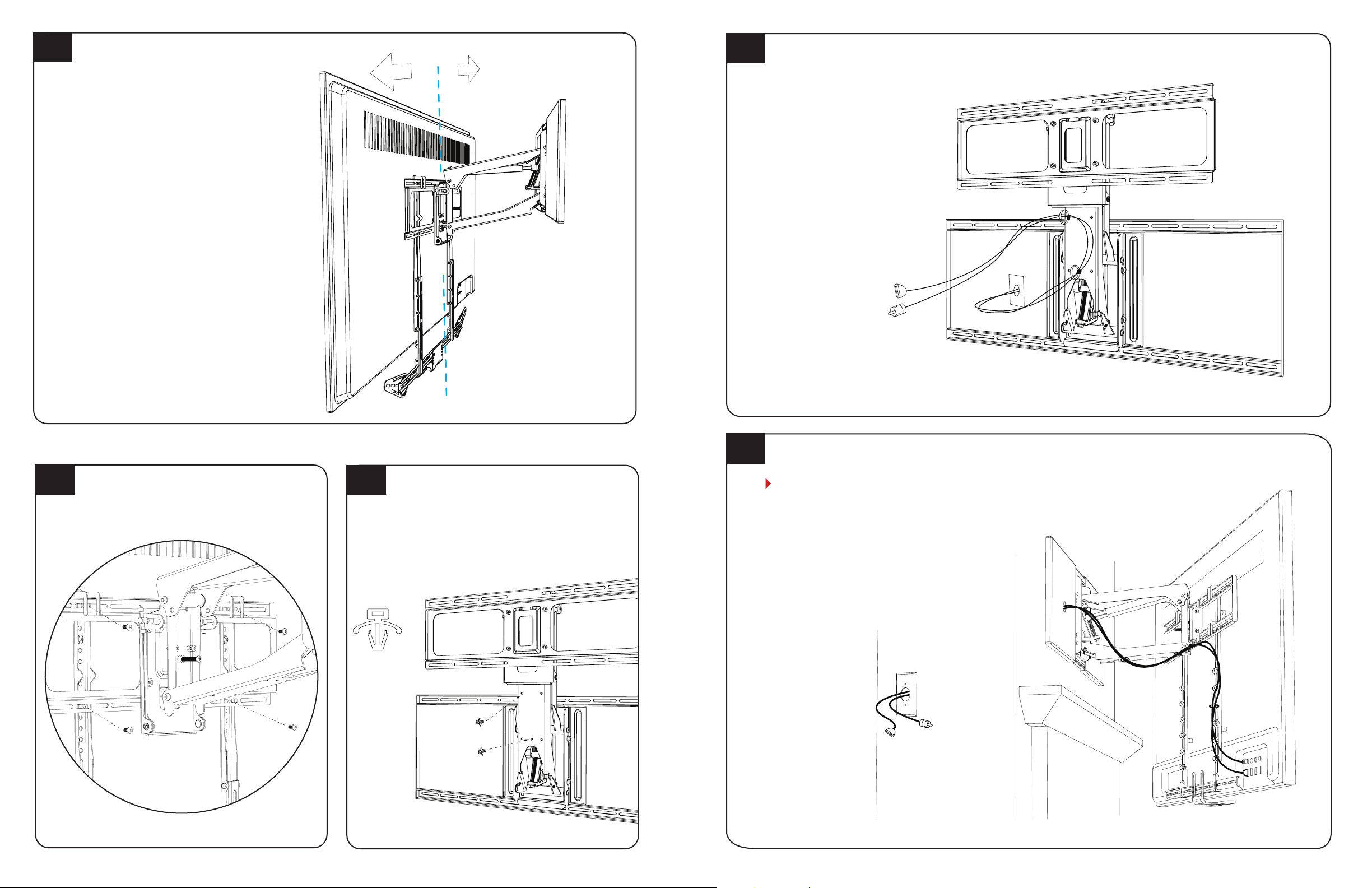
1. Insert the Safety Bolt and Safety Nut (Step 4.1).
2. Detach the TV Brace from the Vertical Braces
(Step 4.4).
3. Remove electrical and signal cables (Step 4.5).
4. Remove the TV from the TV Brace (Step 4.2) and lay
TV face down on a blanketed surface (Step 1.1).
5. Remove the Vertical Brace(s) as necessary.
6. Reposition the Vertical Braces so that they are
properly parallel to one another, then repeat
Step 1, Step 4 and if necessary, Step 5.
1. Insert the Safety Bolt and Safety Nut (Step 4.1).
2. Detach TV Brace from Vertical Braces (Step 4.4).
3. Remove electrical and signal cables (Step 4.5).
4. Remove the TV from the TV Brace (Step 4.2) and
lay TV face down on a blanketed surface (Step 1.1).
5. Slightly loosen all four Lag Bolts (Step 3.4).
6. Adjust Wall Plates so that they are level.
7. Hold Wall Plates in level position and rmly tighten
the four Lag Bolts. Heed warning in Step 3.4.
8. Once the Wall Plates are level, repeat Steps 3, 4 and 5.
Follow the instructions in Step 5.3. Be prepared for
some trial and error. If adjusting the Bottom Stops
doesn’t solve the problem, try the solution below for
when a TV is heavier on one side.
Refer to Step 5.6 and make adjustments.
Attach a counterweight to the back of the TV.
Contact Customer Support for assistance.
TV is not level in the
UP and/or DOWN positions.
TROUBLESHOOTING TIPS
TROUBLESHOOTING TIPS
Customer satisfaction is our top priority!
Following are solutions for the most common installation challenges. For further assistance, visit www.mantelmount.com/troubleshooting or contact
Customer
Support
at
1-800-897-9755
ext.1
or
suppor
[email protected],
Monday
thr
ough
Friday
,
7am
to
4pm
PST
.
NOTE: In rare cases, one troubleshooting adjustment may create the need for another. Be prepared for some trial and error.
The wall covering is
made of brick or stone.
MOUNT SPACE
MOUNT PERFORMANCE
It’s possible to install MantelMount by using concrete anchors (included) with the Lag Bolts {17}, PROVIDED the
brick/stone/wall is structurally sound, several inches thick, and can handle four times the weight of the TV and
mount. Working with a concrete/masonry professional for this type of installation is recommended.
ISSUE
ISSUE
SOLUTION
SOLUTION (May require some trial and error to reach optimal performance.)
The drywall/stucco wall
covering is thicker than 5/8".
Please contact Customer Support for guidance before attempting installation.
A single wood stud is
centered on my wall.
It’s OK to mount the Wall Plates to a single stud by driving two Lag Bolts through the center of the Wall Plates and
into the center stud, as long as the Lifting Arm ends up positioned directly in front of the stud. Alternatively, for a
smaller footprint, replace the Wall Plates with the SSB40 Single Stud Adapter, available at MantelMount.com.
The Lifting Arm won’t
pull down in order to
insert the Safety Bolt.
The mount won’t remain
stationary anywhere
along the route of travel.
It will take some force to pull down the Lifting Arm when it’s in the raised position and there is no TV attached.
As long as the mount is securely attached to a stud(s) in the wall, it won’t break. First, make sure the TV Brace is
attached to the Lifting Arm (see Step 3.7).
Next, pull the Lifting Arm down: Stand in front of the mount, reach up and grasp the top or bottom of the TV
Brace with both hands, palms facing down. Move one foot back for leverage and straighten elbows. Then lean
back, bend both knees and elbows, and pull the mount out and down (see Step 4.1).
Make adjustments to the Lifting Force (see Step 5.1). The combination of the TV’s size and weight, installation
height and mantel depth may aect whether the TV can rest at various positions along the route of travel. What’s
most important is that the TV can comfortably pull down/lift up and stop at the optimal viewing height.
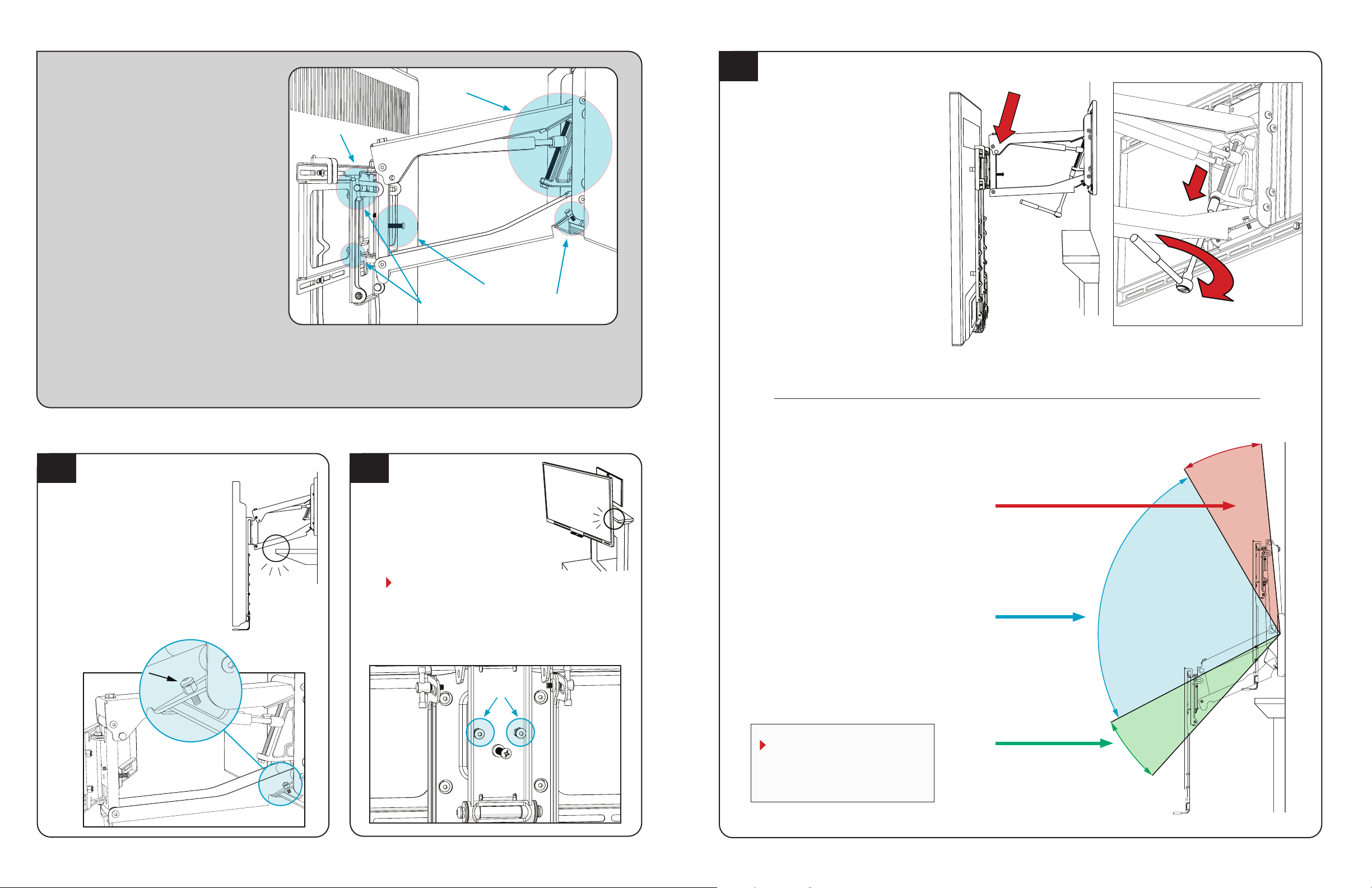
TV is dicult to pull down. Use the MantelMount Three-Step Pull-Down Technique:
1. Stand in front of the mount, arms extended with palms up and elbows straight.
2. Firmly grasp the lifting handles and lean back slightly with one foot forward and one foot back.
3. Step backward with forward foot to pull the mount away from the wall while placing downward
pressure on the handles (keep elbows extended).
If the mount is still dicult to pull down, review Step 5.1, make slight counterclockwise adjustments to the
Lifting Force, and try again. The goal is to adjust the Lifting Force just enough to comfortably pull the TV down
without overcompensating. If it becomes too easy to pull down, it may also become dicult to lift up. Give it a
few practice runs, but be prepared for a little trial and error.
TV is dicult to lift up. If the mount is relatively easy to pull down, slightly tighten it when it’s in the UP position. Review Step 5.1 to
make minor clockwise adjustments to the Lifting Force, then try lifting up the TV again. The goal is to adjust the
Lifting Force just enough to comfortably lift the TV without too much eort. However, if it becomes too easy to
lift up, it may become dicult to pull down.
If you are unable to nd a balance between ease of pulling down and lifting up, follow the instructions above
and focus primarily on making it easier to pull down. Then make adjustments to the Bottom Stop positions (see
Step 5.3). Lower the Bottom Stops to limit downward travel. The less downward travel, the easier it will be to lift.
TV is not lowering the full
vertical travel listed in the
specications.
If you can comfortably pull down and lift the TV but would like for it to drop below the lowest Bottom Stop
Position, remove the Bottom Stop Screws on each side (see Step 5.3); the TV will travel even lower. However,
proceed with caution. If the TV is above a mantel, removing the Bottom Stop Screws may cause the Lifting
Arm to hit the top of the mantel.
CONTINUED ON NEXT PAGE