MantelMount MM815 User manual
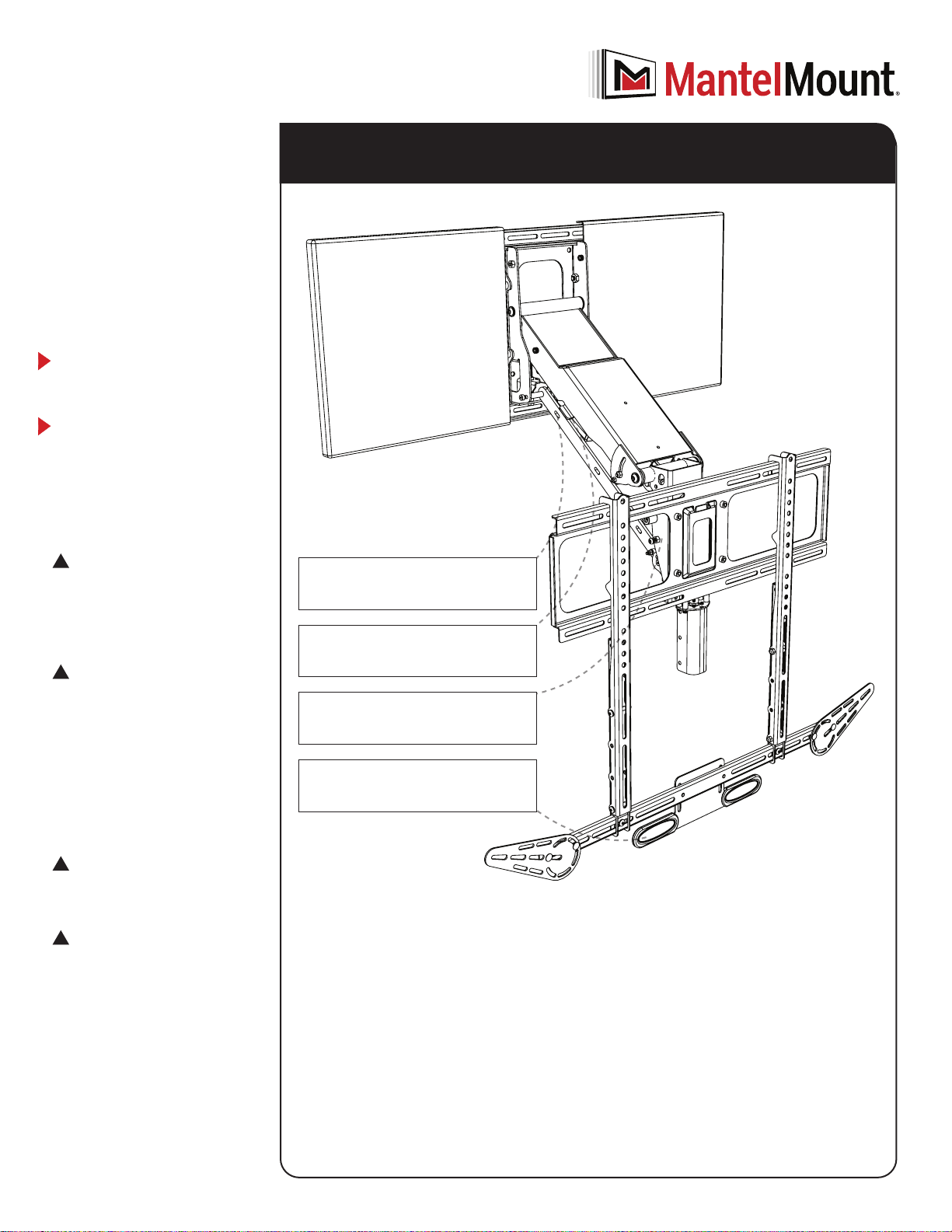
MM815
Motorized
Drop Down
TV Mount
Read this entire manual
before you begin.
Do not unpack
box contents
until verifying the
requirements listed
on page 2.
!
WARNING!
This product contains small parts that
can be a choking hazard. Do not let
children play with any of these small
parts! Keep children away from the
work area during installation.
!
Caution
This product is intended to be installed
by professional installation contractors,
or persons familiar with the tools and
methods required for this installation.
If you are not sure about your ability
to perform this installation, you must
contact a professional. MantelMount
is not responsible for damage or injury
caused by incorrect installation or
improper use.
!
Caution
Do not let children operate, pull on,
or hang from MantelMount.
!
Caution
Do not use this product in any way, or
for any purpose, that is not specically
described in these instructions.
MantelMount is not responsible for
damage or injury caused by incorrect
installation or improper use.
INSTALLATION INSTRUCTIONS
If you need help, call 1.800.897.9755 ext.1
For missing/damaged parts or questions during installation, contact our Customer
Customer satisfaction is our highest priority!
Access a PDF of this manual at MantelMount.com/FAQs/Specs and Manuals.
For more information on MantelMount patented technology visit:
www.mantelmount.com/pages/patents
Contains important safety information – please save! MantelMount.com
Features Include:
Swivel Clutch: Swivel drive automatically
disengages to prevent damage if something
gets in the way of swiveling
Smooth Operation: Solid shafts with
polymer bushings at pivot points provide
silent movement
Motorized Travel: From the comfort of your
couch, move the TV to the perfect viewing
position.
Visual Temperature Sensor: Change to red
color at temperatures above 110ºF to warn
users if the replace is too hot for TV safety

MM815 Installation Instructions
2
BEFORE INSTALLATION
1Verify TV and mount space meet these criteria:
VESA
Width: 200-700mm
Height: 100-500mm
SCREEN SIZE
45" to 90"
(Diagonally)
2 Verify MantelMount will t the wall space.
VESA
Width: 200-700mm
Height: 100-500mm
45"– 90"
VESA COMPLIANT
Up to
600 X 600mm
WEIGHT CAPACITY
20 to 115 LBS.
(Including Sound Bar)
WOOD STUDS FOR MOUNTING
Studs Maximum 28" apart;
Wall Covering Maximum 5/8"
MANTEL DEPTH 16" MAXIMUM
For TVs Shorter then 24. 7” without
a soundbar, mount will be visible in
top position.
VESA
Width: 200-700mm
Height: 100-500mm
MAX 20-115 LBS
16" MAX
WALL SPACE
HEIGHT
TV HEIGHT
MANTEL DEPTH
If Mantel Depth is: Required Vertical Space is:
Less than 8" TV height + 2"
8" – 10" TV height + 4"
10" – 12" TV height + 6"
12" – 15" TV height + 9"
16” TV height + 11”
A. Use the reference diagram (right) and chart (below) to write down the following
measurements (in inches):
Wall Space Height
:(Distance from mantel to ceiling/crown molding.)
TV Height:
(Include sound bar height if placing below TV.)
Mantel Depth:
(Distance mantel extends away from the wall.)
Required Vertical Space:
(Calculation from chart below.)
B. If the Required Vertical Space is less than or equal to the Wall Space
Height, then MantelMount will t the wall space.
STUDS
MAX 28"
APART
3 Verify you have the required tools.
4–5mm
10–13mm
AWL DRILL BIT POWER DRILL
PENCIL LEVELSTUD FINDER WRENCH SOCKET WRENCHALLEN WRENCHES TAPE MEASURER TAPE DISPENSER
OPTIONAL
PAINT
BRUSH
HOLE SAW
PHILLIPS
7/32"
3
{15} x12
M6x12
{18} x4 M6x40
{23} x8
Locknut M6
{14} x4
M8x16
{16} x4
M6x12
{02} x4
M5x30
{01} x4
M5x12
{03} x4
M5x40
{05} x4
M6x30
{04} x4
M6x16
{06} x4
M6x40
{08} x4
M8x25
{07} x4
M8x15
{09} x4
M8x45
{17} x4
Lag Bolt
{20} x1
Safety Bolt
{22}
x2
Anchor
{24} x4
Cable Ties
{17} x4
Lag Bolt
{20} x1
Safety Bolt
{22} x2
Anchor
{24} x4
Cable Ties
BEFORE INSTALLATION
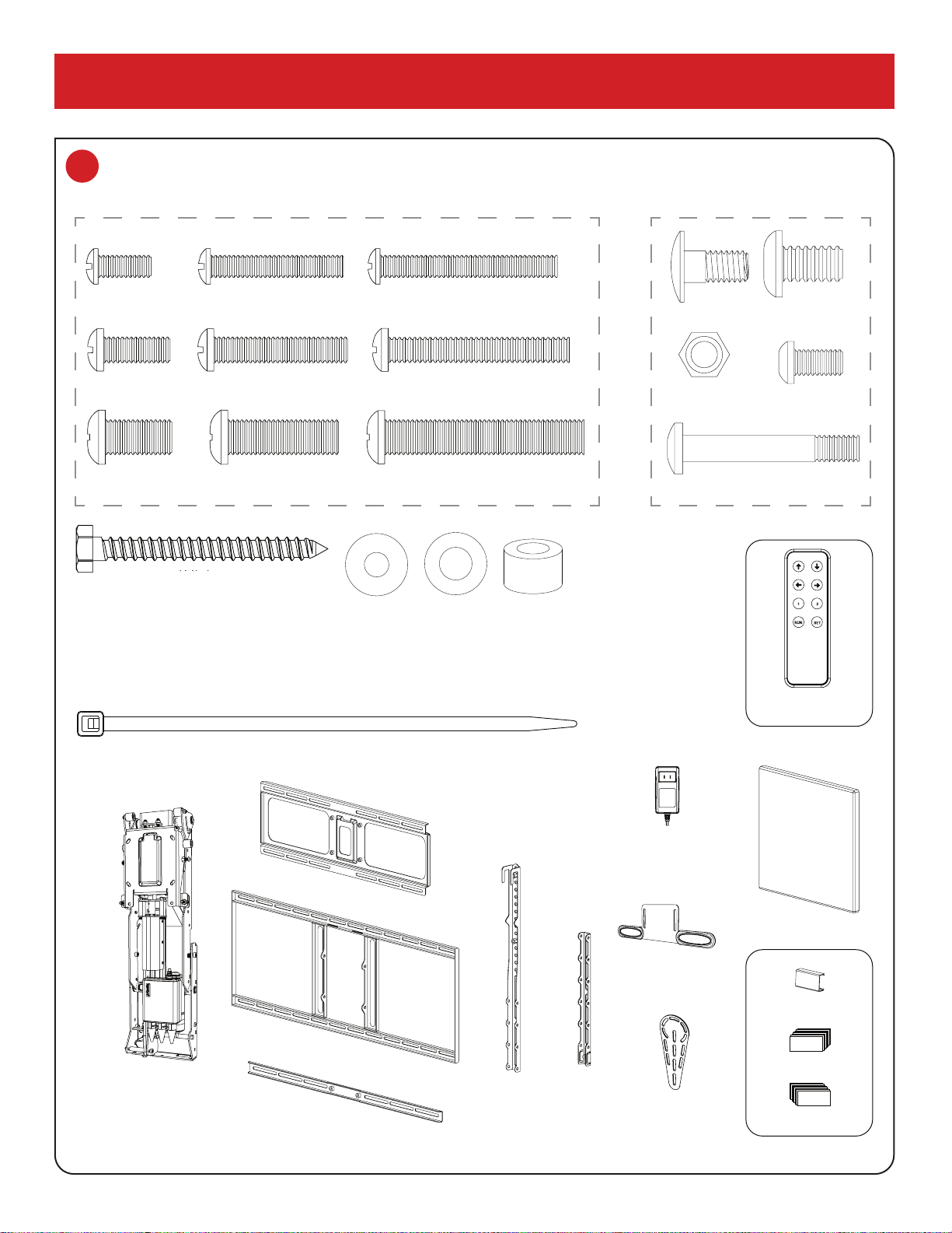
4 Verify all parts are included.
If any parts are missing or damaged, contact Customer Support at 1-800-897-9755 x1 before installing.
SILVER SCREWS FOR BACK OF TV BLACK PARTS FOR MOUNT
Thread patterns may vary.
{10} x4
M5-M6
{11} x8
M8
{12} x12
Spacer
{10} x8
M5-M6
{10} x4
M5-M6
{11} x8
M8
{12} x12
Spacer
{11} x8
M8
{10} x4
M5-M6
{11} x8
M8
{12} x12
Spacer
{12} x12
Spacer
{24} x4 Cable Ties
{17} x4 Lag Bolt
{10} x4
M5-M6
{11} x8
M8
{12} x12
Spacer
{17} x4
Lag Bolt
{24} x4
Cable Ties
{57} x2 Wall Cover
{32} x1 Wall Plate
{35} x1
Lifting
Mechanism {55} x1 Horizontal Brace
{30} x2
Brace
Extender
{33} x1 TV Brace
{31} x2
Vertical
Brace
{02} x4
M5x30
{01} x4
M5x12
{03} x4
M5x40
{05} x4
M6x30
{04} x4
M6x16
{06} x4
M6x40
{08} x4
M8x25
{07} x4
M8x15
{09} x4
M8x45
{52} x2
Sound Bar Wing
{219} x1
Visual Heat Sensor
{60} x1
Wall Plug
{63} x8 Wall Clip
{25} x8 Velcro Hook
{26} x8 Velcro Loop
{15} x16
M6x10
{18} x4
M6x40
{23} x8
Locknut M6
{14} M8x4
{227} x1
RF Remote
MM815 Installation Instructions
4
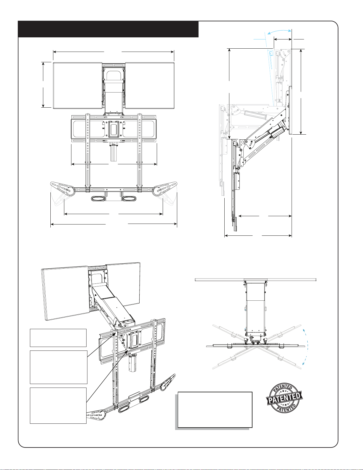
37. 5
30
40 MA X
14. 0
MM815 Pull Down TV Mount
Ask us about our new
* Recess Box Kit *
that hides MantelMount
inside the wall !
© 2022 MANEHU PRODUCT ALLIANCE, LLC. For more information on MantelMount patented technology visit: www.mantelmount.com/pages/patents
Maximum Drop
Thickness
3–4°5.1
26
15
18
24.7
26
MantelMount has three dierent adjustments that must be made
after the installation is complete in order to operate properly.
The Centering Cams
automatically swivels the
TV to center while raising
to avoid permanent
obstacles.
The side-to-side swivel
stops are adjusted via
remote control and with
two screws so that the
TV does not swivel into
the mantel.
The bottom travel stop
is adjusted with the
remote control.
30˚ R
30 ˚L
30˚ R
30 ˚L
Note: As the mount lowers, rst it tilts down. As it keeps
lowering, it normalizes, becoming vertical about 6 inches
down.
Bottom Clearance
Max. Clearance

5
Remote Control Functions
Home Position: To return mount to the home
position press: Run then arrow. This will
Auto-Swivel mount to center position and raise
mount to the topmost position.
Stop: Press any button to stop movement
Set Memory Position: To Set Positions 1, 2
• Drive the mount to the desired Position
• Press Set
• Press the Memory button (1, 2)
System Reset: If the mount is not working as
expected, updates calibration while keeping
set limits
• Press Set
• Press Run
• Press/Hold Set
• Mount will move to the top position
• Keep holding for 5 seconds after mount
reaches top position
Set Left/Right/Bottom Limit:The Mount will
not drive past
• Drive Mount to desired limit
• Press Set
• Press one of ( )
• Press/Hold Set for 4 to 8 Seconds
• Check it was correctly done by trying to
move the mount past limit
Clearing Any Memory Position: A position
does NOT need to be cleared to change it.
• From any Position
• Press Set
• Press button to clear
(12 )
• Press/Hold Set for at least 11 Seconds
Automatically Move to Position
The mount can be automatically moved to any
set position without having to hold the button.
To do this, press Run and then the Position
Button ( 12 ). To stop movement,
simply push any button on the remote.
When Auto-moving, the mount will center the
swivel, go to the required height, then swivel
to position.
Note: Press each button rmly; a quick tap
probably will not work.
Remote Control Buttons
Move the mount up to the top
most position
• Hold to drive to position
Move the mount down to the bottom most
set position
• Mount cannot be driven lower then
set limit
• Comes set for lowest bottom position
• Hold to drive to position
Swivel the mount to the right most
set position
• Mount cannot be driven past
set right limit
• Comes set for 30 degrees of swivel
to the right
• Hold to drive to position
Swivel the mount to the left most
set position
• Mount cannot be driven past
set left limit
• Comes set for 30 degrees of swivel
to the left
• Hold to drive to position
1Move the mount to the set 1 position
• Mount will drive to this position from
either direction
• Does not come set out of the box
• Hold to drive to position
2Move the mount to the set 2 position
• Mount will drive to this position from
either direction
• Does not come set out of the box
• Hold to drive to position
Run Automatically move to the position
selected ( 12 )
• Press Run
• Press one of ( 12 ) within
3 seconds
• The mount will move to the limit
automatically
• Press any button to stop movement
• For Auto-Moving, the mount will rst
swivel to center position (0 degrees),
adjust height, then swivel.
Set Used to Set and Clear Positions.
BEFORE INSTALLATION
1 Learning Your Remote Functions.
Remote Buttons
Up Button
Down Button
Swivel Right
Swivel Left
1Memory 1
2Memory 2
RUN Run Button
SET Set Button
Pairing RF Remote
Controller should be already
paired out of the box.
• Unplug Power to mount for
30 seconds
• Hold the button while
plugging in power.
• keep holding button
for 10 seconds
The RF remote requires a
CR2032 battery
Quick Note: To return mount to the home position press: Run then arrow.
This will Auto-Swivel and move mount to the topmost position.
MM815 Installation Instructions
6
MM815 INSTALLATION STEPS
STEP 1 Attach Braces to TV
.....................................PAGE 5
STEP 2 Determine Wall Placement
..............................PAGE 8
STEP 3 Attach Mount to Wall
....................................PAGE 11
STEP 4 Attach TV to Mount
.....................................PAGE 13
STEP 5 Make Final Adjustments
.................................PAGE 16
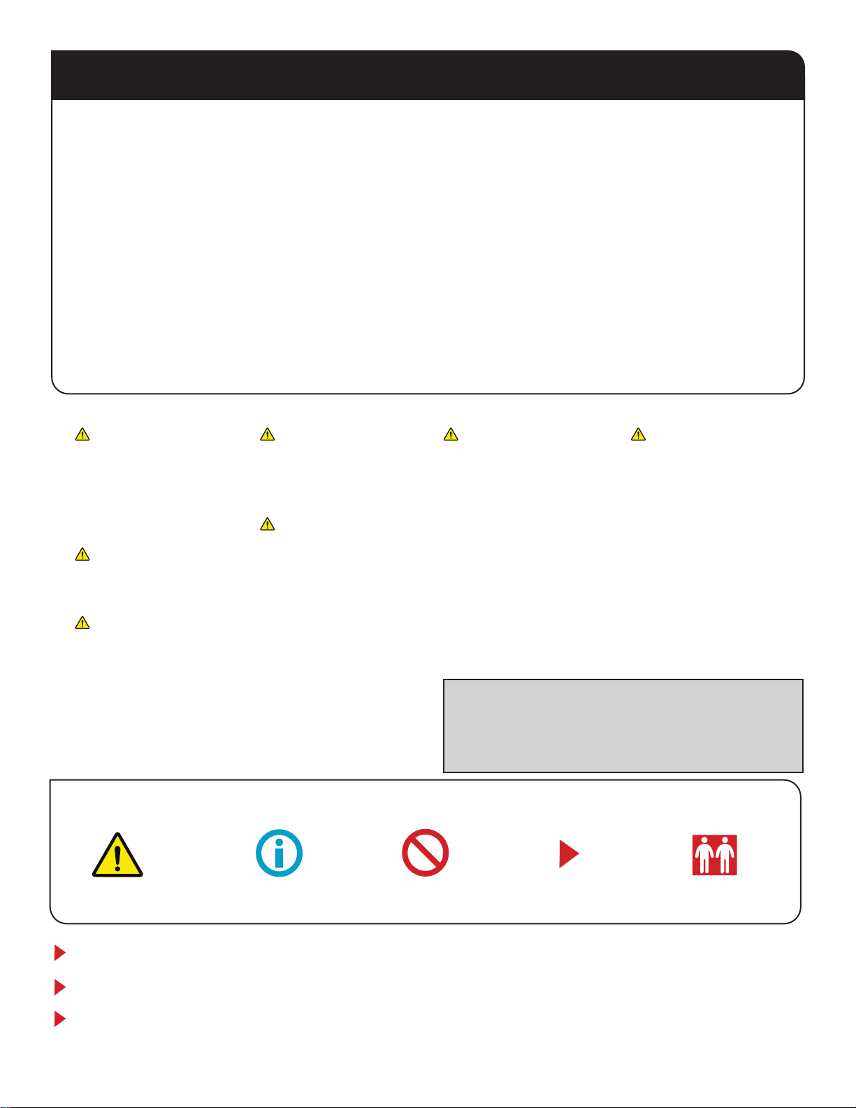
CAUTION / WARNING SPECIAL NOTE REQUIRES TWO PEOPLE
DO NOTHELPFUL INFORMATION
Symbols Used in this Manual
Installation Tips & Videos: http://mantelmount.com/install-tips
Questions during installation? Contact Customer Support:
Monday – Friday, 7am– 4pm PST 1.800.897.9755 x1 or support@mantelmount.com
Two people required for parts of this installation.
Pinching and Crushing
Hazard: The wall mount
actuation is very strong, do
NOT run the mount when
anyone is near the mount.
Do NOT have any part of
the body in the mount or
between the TV and Wall. The
Mount will keep driving until
someone pushes another
button on the remote to
stop it. When working on the
mount unplug the power.
Keep children away from the
work area during installation.
This product contains small
parts, please keep out of reach
from children.
WARNINGWARNING
Do not let small children
pull on or hang from
MantelMount.
WARNINGWARNING
WARNINGWARNING
This product is intended to
be installed by professional
contractors or persons
familiar with the tools and
methods required for this
installation.
If you are uncertain about
your ability to perform this
installation, please contact a
professional.
Do not use this product in any
way or for any purpose that is
not specically described in
these instructions.
CAUTIONCAUTION
Do not use this product for
purposes not specically
described in these
instructions.
MantelMount is not responsible
for damage or injury caused
by incorrect installation or
improper use.
MantelMount is not responsible
for damage or injury caused
by incorrect installation or
improper use.
CAUTIONCAUTION
Do not remove any bolts that
hold the Lifting Arm together.
WARNINGWARNING
Moving the mount before all
limits are set may result in
damage. Complete all steps
in the manual before using
the mount.
WARNINGWARNING
WARRANTY: MantelMount oers a Lifetime Limited Warranty for all
TV mounts and accessories. This Lifetime Limited Warranty covers
all mechanical parts but excludes lifetime coverage for gas springs
or electrical parts which are warrantied for ve (5) years from the
original purchase price.

7
Select Screws and Spacers.
If Spacers {12} are required, choose one of these Screw
combinations shown with maximum Spacer usage.
{02}
{01} {10}
{10}
{10}
{10}
{11}
{11}
{11}
{12}
{12}
{10} {12}
{10}
{12}
{12}
{12} {12}
{12} {12}
{12} {12}
{12}
{12}
{03}
{05}
{04}
{06}
{08}
{07}
{09}
M5
M6
M8
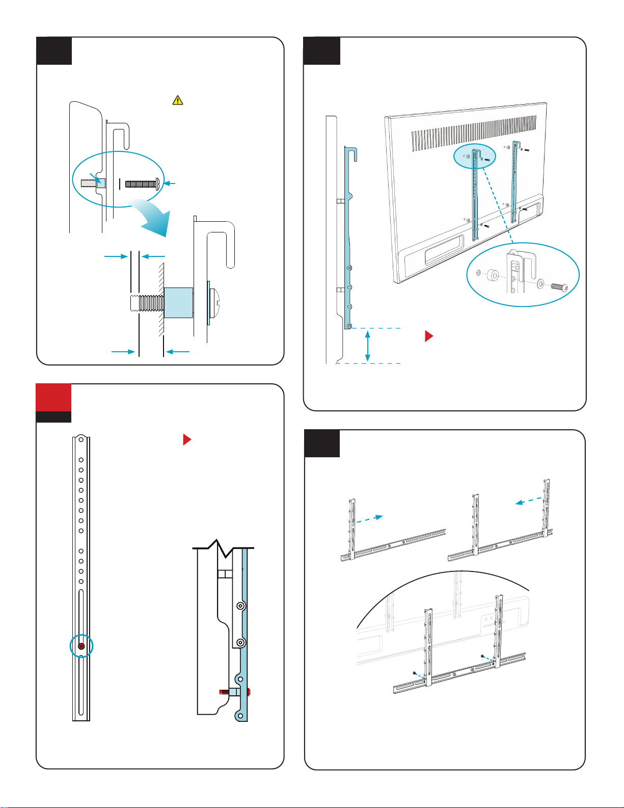
Test-t Brace components on back of TV.
Place TV screen-side down on a at, blanketed surface.
Lay out components to check assembly conguration. If
installing a sound bar, refer to STEP 1.8.
1.1
STEP 1
Attach Braces
to TV
*
Determine if TV has a at or irregular back.
An irregular back will require Spacers {12} and longer
Screws to ll spaces between the Vertical Brace {31} and
the TV. The Braces must be parallel to television screen.
Flat Back TV
Irregular Back TV {12}
{12}
{31}
{31}
Irregular Back TV
(Recessed Threads)
{31}
{31}
{30}
{219} {55}
{31}
{30}
BACK
OF TV
1.2
1.3
In order for the TV to hide the Mount on the wall, the
Braces must be at least 3” higher than the bottom of TV
(or Soundbar if one is installed).
If you are using an RB100 Recess Box then they must be
6“ higher to hide the Recess Box.
MM815 Installation Instructions
8
If the lower VESA holes are less than 3" from the
bottom of the TV:
Connect the Vertical
Braces {31} through
the UPPER VESA
holes only, so that
the bottom of the
braces are between
3" to 10" from the
bottom of the TV. *
If the only option is
to attach the Vertical
Braces to the Upper
Vesa holes through a
slot: 1) Hand-thread
the screw through
the slot; 2) slide the
Vertical Brace upward
until the screw meets
the bottom of the
slot; and 3) tighten
the screw.
You must attach the
Brace Extenders {30}
to the Vertical Braces
as described in STEP
1.7. However, you
must also attach the
LOWER VESA hole
through the Brace
Extender as shown.
SIDE VIEW
{31}
{55}
{15}
{15}
{30}
{31}
{31}
{30}
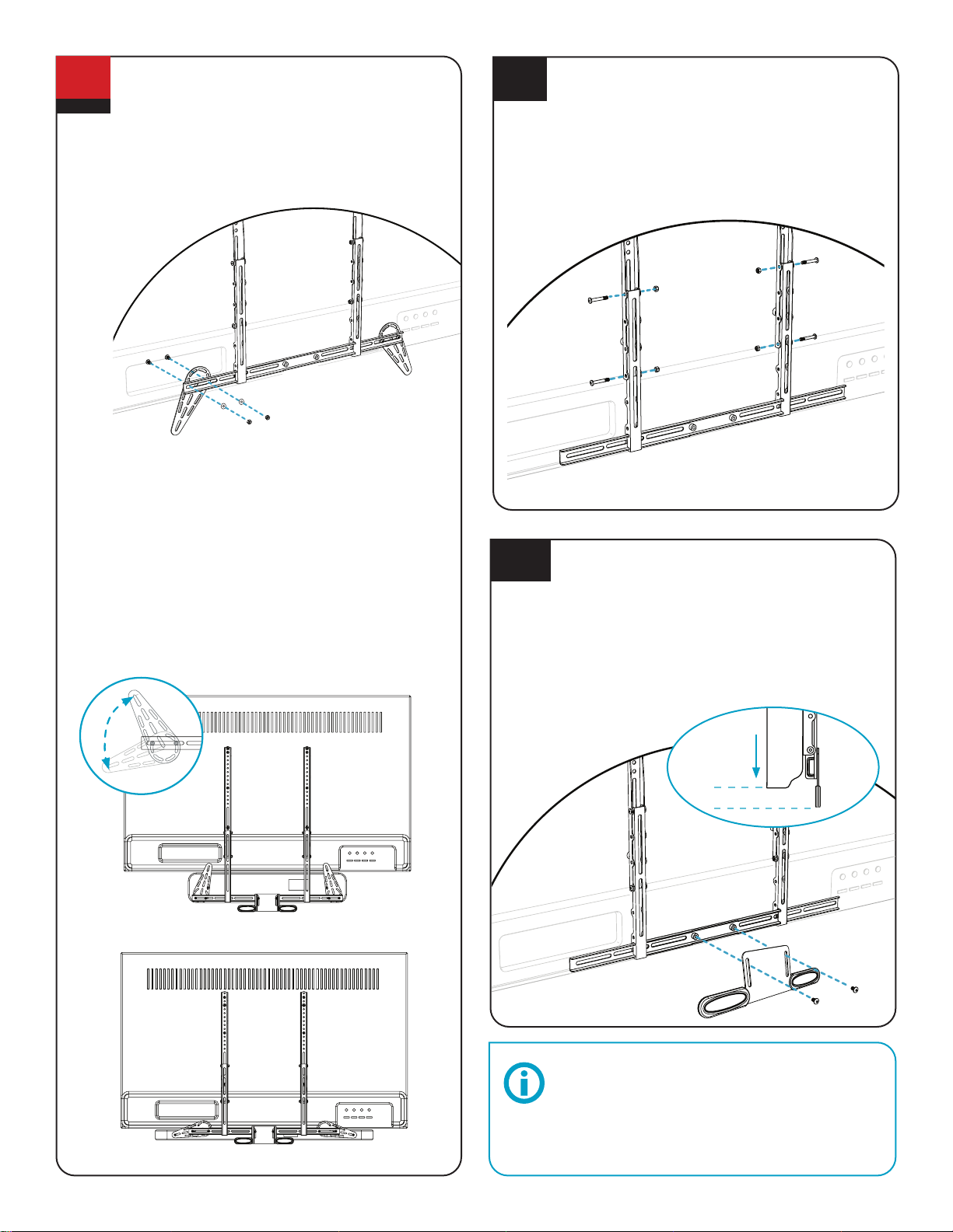
Attach the Horizontal Brace to Brace Extenders.
Slide one Brace Extender {30} onto the left end of the
Horizontal Brace {55}, then slide the other Brace Extender
onto the opposite right end.
Attach the Vertical Braces to the back of TV.
Install the Vertical Braces {31} so that the bottoms of the
braces are between 3" to 10" from the bottom of TV,
(*or Soundbar if one is installed) centering the braces
vertically as much as possible.
{31}
3 to 10
INCHES *
SIDE VIEW
{31}
{31}
VERTICAL BRACES MUST ALWAYS
BE INSTALLED HIGHER THAN THE
BOTTOM OF THE TV.
If the lower VESA holes are less than
3" from the bottom of the TV, go to
STEP 1.6; otherwise skip to STEP 1.7.
Hand-thread screw combination into the TV.
Ensure there is adequate thread engagement
without hitting the bottom of threaded insert.
Do not use screws that
are too long for the TV’s
threaded inserts because
it may damage internal
components!
MUST LEAVE
A GAP IN
THREADED
TV INSERT
MAXIMIZE THREAD
ENGAGEMENT FOR
STABILITY
AFTER ASSEMBLY
(ENLARGED)
{12}
CAUTIONCAUTION
TV SCREW
UPPER
VESA
HOLE
WITH
SCREW
IN PLACE
LOWER
VESA
HOLE
WITH
SCREW
IN PLACE
Align the Brace Extenders with the Vertical Braces
(that are already mounted to the back of the TV) while
positioning the Horizontal Brace so that it extends an
equal amount on either side of the Brace Extenders.
Attach Horizontal Brace to Brace Extenders w/Screws {15}.
{30}
{55} {55}
{30}
*
If installing this mount with a MantelMount RB100 Recess Box,
the bottom of the Vertical Brace must be 6”-10” from the bottom of
TV (or 6” from the bottom of the Soundbar if one is installed).
*
If installing this mount with a MantelMount RB100 Recess Box,
the bottom of the Vertical Brace must be 6”-10” from the bottom of
TV (or 6” from the bottom of the Soundbar if one is installed)..
1.4
OPTIONAL
1.6
1.5
1.7
{30}
9
Use Screws {16}, M6 Washers {10}, and Nuts {23} to
attach the Sound Bar Wings {52} to the Horizontal
Brace {55}. Position the Wings to t the mounting
holes of the sound bar. Install sound bar. See below
for Sound Bar Wing installation information.
{16}
{15}
{219}
Attach Visual Heat Sensor to the Horizontal Brace.
Attach the Visual Heat Sensor {219} with Screws {15} to
the Horizontal Brace {55}, Set the height so the Visual
Heat Sensor is as visible as desired.
Note: If using the minimum height from chart in Step
2.2, keep the exposed heat sensor pad no more than 1”
below the TV or soundbar. When rst moving the mount
down ensure the visual heat sensor clears the mantel.
{55}
{53}
1” Max below
TV or Soundbar SIDE
VIEW
{52}
{52}
{55}
{23}
{10}
Protect the TV with the Visual Heat Sensor.
The Visual Heat Sensor turns red if the temperature
above the replace exceeds a safe 110° F – a visual cue
that either the TV needs to be raised to the UP position
or the replace needs to be turned o.
WIDE
WIDE
Arrange Sound Bar Wings and sound bar to work with
the Visual Heat Sensor.
The Sound Bar Wings may be positioned and rotated so
that the Visual Heat Sensor {219} will reach below the
sound bar.
For example, if a sound bar is tall, the Brace Extenders
{30} and Horizontal Brace can be attached lower down on
the Vertical Braces toward the bottom of the sound bar
while the Wings point upwards in order to align with the
sound bar’s installation holes.
TALLER SOUND BAR
WIDER SOUND BAR
OPTIONAL
1.8
Attach Brace Extenders to the Vertical Braces.
Slide the Brace Extenders {30} (with the Horizontal Brace
{55} now attached to them) onto the Vertical Braces {31}.
Position it so that the Horizontal Brace will be hidden by
the TV. Use Screws {18} and Nuts {23} to attach.
{23}
{18}
{23}
{23}
{31}
{31}
{30}
{30}
{55}
{18}
{18}
1.9
1.10
MM815 Installation Instructions
10
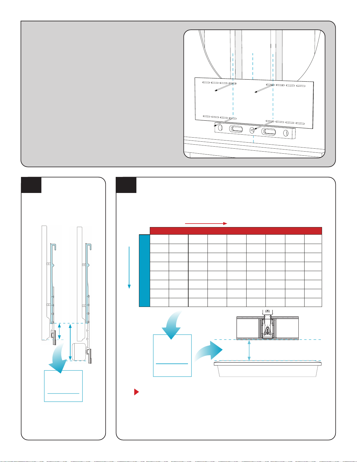
STEP 2
Determine
Wall Placement
Measure the distance
from the bottom of the
Vertical Braces {31} (not
the Extenders) to the
bottom of the TV/
sound bar.*DEPTH OF MANTEL
{31}
10.50"
9.50"
8.50"
7.50"
6.50"
5.50"
4.50
3.50
8" OR LESS
11.00
10.00
9.00
8.00
7.00
6.00
5.00
4.00
9"
10.75
9.75
8.75
7.75
6.75
5.75
4.75
3.75
10"
11.80
10.80
9.75
8.75
7.75
6.75
5.75
4.75
11"
12.50
11.50
10.50
9.50
8.50
7.50
6.50
5.50
12"
13.50
12.50
11.50
10.50
9.50
8.50
7.50
6.50
13"
14.80
13.80
12.80
11.80
10.80
9.75
8.75
7.75
14"
16.30
15.30
14.30
13.30
12.30
11.30
10.30
9.25
15"
18.50
17.50
16.50
15.50
14.50
13.50
12.50
11.50
16"
7"
8"
9"
10"
3"
4"
5"
6"
DISTANCE
FROM 2.1
DISTANCE
MINIMUM DISTANCE BETWEEN MANTEL
AND LOWER WALL PLATE HOLES
MEASURE
THIS
DISTANCE
Determine the minimum vertical position of the Wall Plate.
Use the Look-up Table below to nd the minimum distance between the mantel and
the bottom of the lower Wall Plate {32}. This will be the intersection of the distance
from STEP 2.1 and the mantel depth. Write the minimum distance in the box below.
Most customers want their TV mounted as close to the mantel as possible. If this
describes you, go directly to STEP 2.4.
However, if you want the TV higher on the wall (such as centered between the
mantel and ceiling) e.g. for extra space on the mantel for pictures or a center speaker,
continue to STEP 2.3.
VALUE FROM
LOOK-UP TABLE
*If installing this mount with a MantelMount
RB100 Recess Box, the bottom of the Vertical
Brace must be 6”-10” from the bottom of TV
(or 6” from the bottom of the Soundbar if
one is installed).
2 .1 2.2
11
(E)
Distance between
mantel and lower
wall plate holes
OPTIONAL Some customers want the TV centered between the mantel and the ceiling or crown molding. Others want enough space below the TV
for pictures or a center speaker.
The TV’s position on the wall is directly related to the placement of the lower Wall Plate. To determine exactly where to place the lower
Wall Plate, choose an option below that best describes your scenario and ll in the boxes.
NOTE: Distance “E” below must always be at least the minimum distance in STEP 2.2
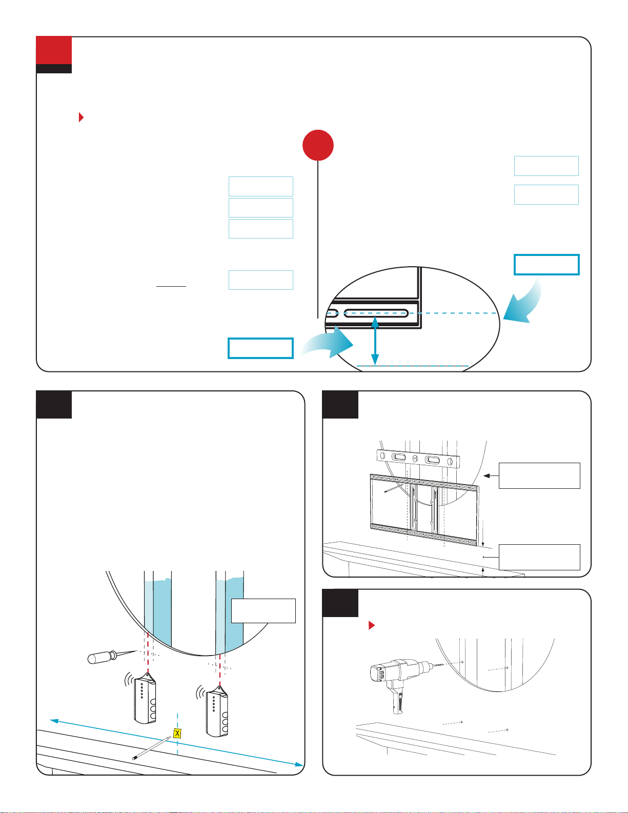
Determine a higher vertical position of the Wall Plate.
Find the center of your mantel and the centers
of two studs.
Measure and mark the center line of the mantel onto the
wall with tape.
Next, use a stud nder to locate two studs, one on each
side of the centerline. (If you prefer to use one center stud
alone, see “Mount Space” in the Troubleshooting Tips on
page 22.)
Then, at the height from either Step 2.2 or 2.3, locate the
center of the stud(s) by poking a sharp awl or nish nail
through the drywall to nd each stud edge. Mark these
center spots on the wall. Lag Bolts must be installed into
the CENTER of the studs in STEP 3.1.
AWL
STUD FINDER
C
L
Cutout shown
for reference
Option 1: I want the TV centered between the mantel
and ceiling/crown molding.
1. Record measurements already taken:
Wall Space Height from pg. 2 (A)
TV Height from pg. 2 (B)
Distance from STEP 2.1 from pg. 8(C)
2. Subtract the TV Height (B) from the Wall Space Height (A),
then divide by 2.
(A) – (B) =
3. Add (C) and (D) to determine how many inches above
the mantel to place the lower Wall Plate holes.
(C) + (D) =
Option 2: I want the TV a specic distance above
the mantel.
1. Record distance from STEP 2.1 from pg. 8(C)
2. Write the specic number of inches
you want between the mantel and
the TV (or TV with sound bar):
3. Add (C) and (D) to determine how many inches above
the mantel to place the lower Wall Plate holes.
(C) + (D) =
2
(D)
(E)
(E)
(D)
OR
Align the arrows on the Wall Plate {32} pointing upward. Center
and level the plate above the mantle and position the height
using the table in STEP 2.2. Mark the 4 spots for lag bolts
directly on center of the studs.
Pre-drill the 4 holes with 7/32” drill bit to a depth of 2.5
inches (65mm) including wall covering.
Note: Wall covering (drywall) must not exceed
5/8” thickness.
2.3
2.4 2.5
2.6
Minimum Height
from STEP 2.2
Cutout shown
for reference

MM815 Installation Instructions
12
BEFORE
Wall plate impeded by outlet.
BEFORE
If the wall plate sits directly behind lifting
arm wall plate must be moved up.
After
Wall Plate lowered to clear outlet.
After
Wall plate moved up to clear outlet.
If necessary, move Wall Plates to clear an outlet.
If a Wall Plate installation is impeded by an electrical outlet (or other) and professionally relocating the outlet is
impossible, try one of these two options:
Move Wall Plates up or down to clear the outlet. As long as you don’t place the LOWER Wall Plate below the
Minimum Distance (Step 2.2) or above the Maximum Distance (step 2.3), MantelMount will still function properly.
Simply move the Wall Plates up or down enough to clear the outlet, leaving them as close as possible to the
originally planned vertical positions.
IMPORTANT: You must now move the Vertical Braces {31} on the back of the TV using the same number of inches
used to move the Wall Plates (e.g., move the Vertical Braces down 2" if the Wall Plates were moved down by 2" ).
The bottom of the Vertical Braces must remain between 3 to 10 inches from the bottom of the TV.
OPTIONAL: If you prefer to drill an access hole in your wall plate cover, the outlet may be placed within the
footprint of the wall plate.
Move the Wall Plates up enough to clear the outlet, leaving them as close as possible to the originally planned
vertical positions.
IMPORTANT: You must now move the Vertical Braces {31} on the back of the TV using the same number of inches
used to move the Wall Plates (e.g., move the Vertical Braces up 2" if the Wall Plates were moved up by 2" ).
The bottom of the Vertical Braces must remain between 3 to 10 inches from the bottom of the TV.
NOTE: If outlet is directly behind the Lifting Arm, the only solution is to move the Wall Plates up.
2.7

13
Attach the Wall Plate {32} with arrows up, using Lag Bolts
{17} and Washers {11} directly into the centers of the studs
With a 13mm wrench.
3.1
: Do Not overtighten Lag Bolts {17}. Tighten
only until the washers are rmly against the wall plate. Damage
due to overtightening can cause property damage or injury.
STEP 3
Attach Mount
to Wall
Power up the mount. Plug Power Supply into mount
then into wall socket. The TV remote should work out of
the box. Move Mount Down 2 Inches by holding .
If TV remote does not work it needs to be paired.
To Pair Remote:
1. Unplug Power to mount for 30 seconds
2. Hold the (DOWN) button while plugging in power
3. Keep holding (DOWN) button for around 10 seconds
until mount moves down
Run System Reset – System reset ensures software is
running correctly. Press Set. Press Run. Press/Hold Set.
Mount will move to the top position. Keep holding for 5
seconds after mount reaches top position.
3.3 3.4
1
2
Insert bottom tabs of Lifting Mechanism {35} into the slots
of Wall Plate {32} then slide the top into position. Align all
four holes and install Screws {14}. Tighten Securely.
3.2
Press and hold.PressPress
Press and hold DOWN
button for 10 seconds.
Note: Do NOT let go of Lifting Mechanism
{35} until Screws {14} are installed.
MM815 Installation Instructions
14
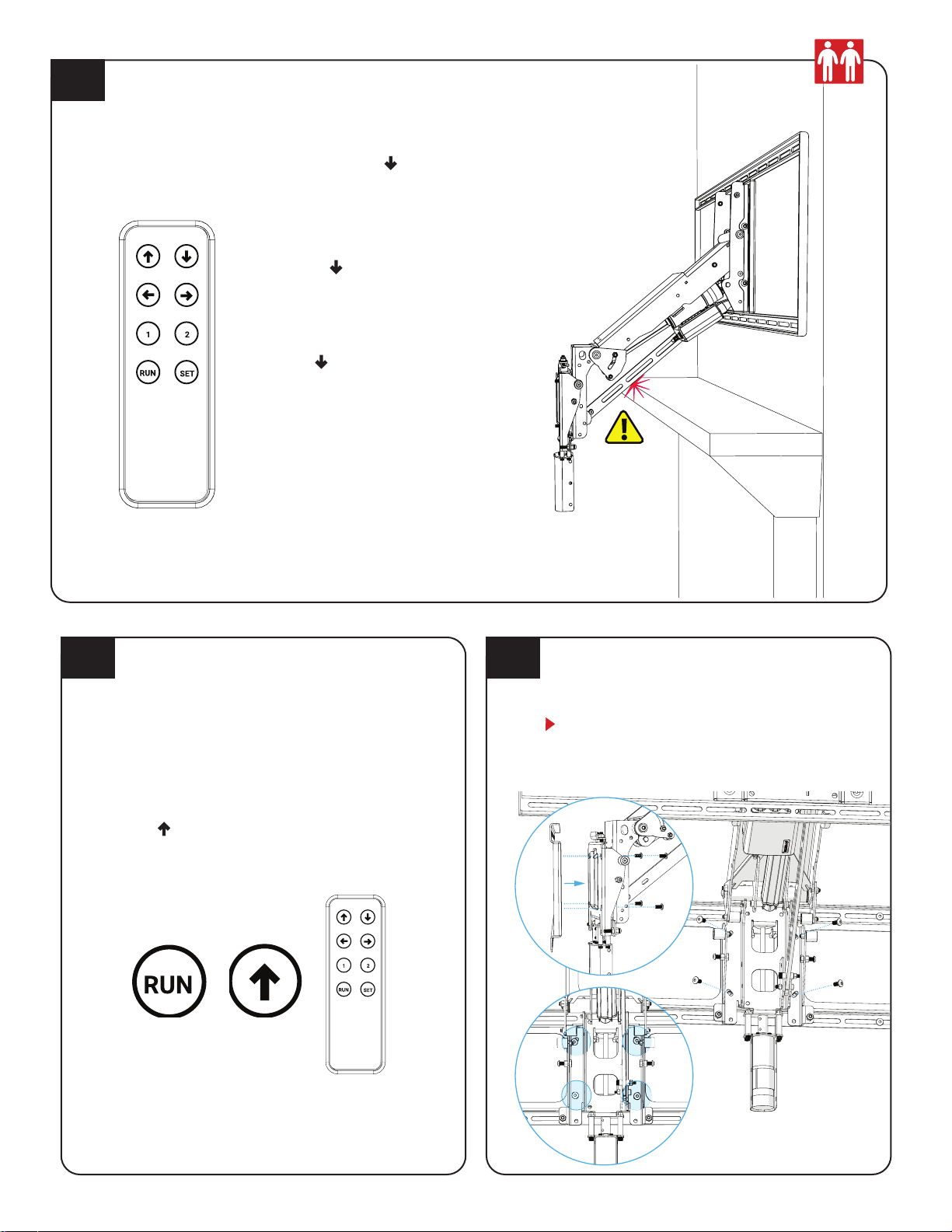
Programming Bottom Stop
Warning: Damage will occur If the Mount can drive down into
something, the bottom stop needs to be set.
If the mount would hit the Mantel or some other object in the bottom
position. You can easily reduce the bottom most ( ) position so that the
mount cannot move past that point.
3.5
1. Drive mount to the desired
Bottom-most Position by
holding
2. Do NOT allow the mount to
run into anything
3. Press Set
4. Press
5. Press/Hold Set for 4 to 8
Seconds
6. Check it was correctly done
by trying to move the mount
down farther
Note: To delete the bottom stop follow
steps 3 to 6 but hold the set button for
more than 10 seconds in step 5.
Attach the TV Brace {33} to the lifting arm {35}. Manually
Swiveling the Swivel Plate will make accessing the screw
holes easier. Level the TV Brace and tighten the 4 screws
{15}.
NOTE: After TV is mounted to bracket you may need
to adjust these screws to make nal Post-Leveling
adjustments (Step 5.6).
3.6 3.7
Swivel Safety Clutch
The Swivel on the mount has a friction clutch that
automatically disengages to avoid damage if the mount
swivels into something, or someone swivels the mount
manually. If that happens the swivel will be out of position
and the swivel will not work as expected. The swivel needs
to be recalibrated right away to avoid damage.
To recalibrate Auto-move the mount to the top position:
Press Run
Press within 3 seconds
The mount will automatically move to the top position and
recalibrate. You can also run Reset Function to recalibrate.
Note: If clutch is engaged the mount may swivel a little when
coming down, to fix this; manually center mount at zero degree
swivel by rotating TV with hands and over-riding clutch. Mount is
at zero degrees swivel after you recalibrate (drive the mount to the
top position), then move the mount straight down.
Press within
3 Seconds
Press
15
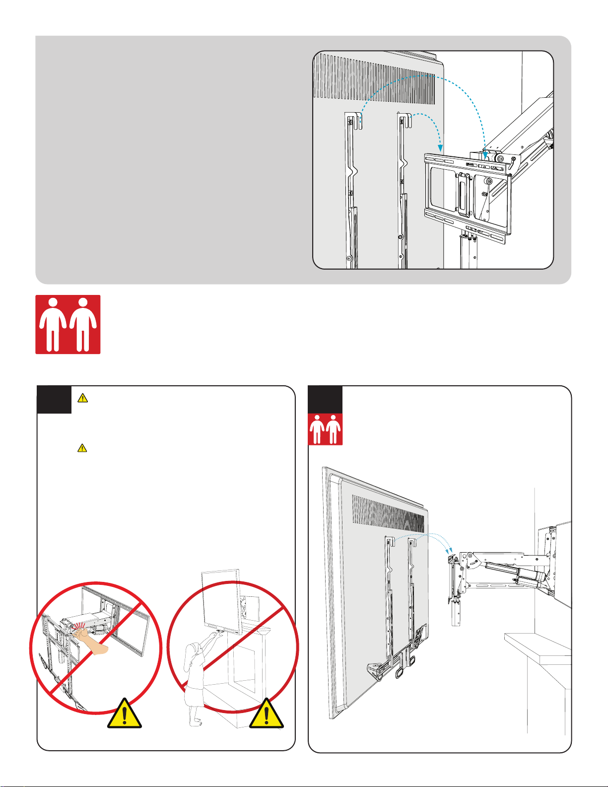
STEP 4
Attach TV
to Mount
NOTE: These Next Steps Will Require Two People
4.1
WARNING!
Do Not put hands into Lifting Mechanism. The power of
the Lifting Mechanism can cause bodily injury!
Pinching and Crushing Hazard.
The wall mount actuation is very strong, do NOT run the
mount when anyone is near the mount. Do NOT have
any part of the body in the mount or between the TV and
Wall. The Mount will keep driving until someone pushes
another button on the remote to stop it. When working on
the mount unplug the power.
Never allow small children to play around or operate
the MantelMount. Property damage or personal injury
can occur.
This step requires two people.
Carefully hang the Television onto the TV Brace
making sure that both hooks on the Vertical Braces
{31} engage the TV Brace {33}.
4.2
MM815 Installation Instructions
16
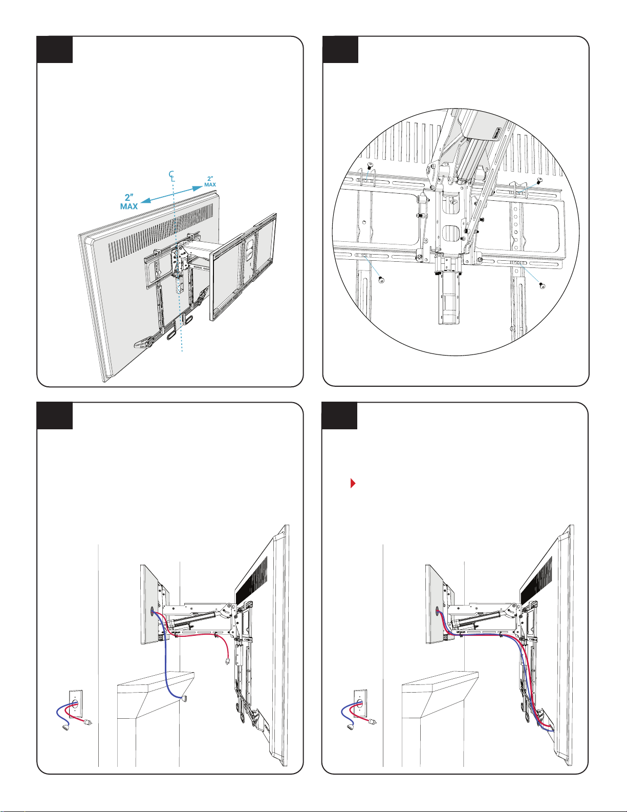
Center the TV on the TV Frame and check it with a level.
Carefully slide the TV sideways, if required, until it is
balanced and horizontal, up to a MAXIMUM OF 2 INCHES
left or right.
The TV would only need to be moved o-center if it has an
unbalanced weight. These are usually older, heavier TVs.
If the TV needs to be moved sideways and is visually too
much o-center above the mantel, remove the TV and
relocate the Wall Plate {32} an equal distance but in the
opposite direction of the TV to compensate.
4.3
Attach the electrical and signal cables to the TV.
Run signal cables through open loop. Give each segment
of the cables extra length so that they are not stressed or
kinked when the mount moves.
Ensure that cables do not get pinched within the Lifting
Arm when the TV is raised.
Reference Only: This is one possible conguration for
the signal cables. Each segment of the cables has extra
length so that the cables are not stressed or kinked when
the mount is moved.
Attach cable ties to lower arm.
Shown below is the easiest way to attach cables. Use the
included Cable Ties {24} to attach cables so they attach to
the underside of the Lower Arm, making a gentle loop.
Cables should be long enough to accommodate the
extension and swivel of MantelMount. Check all ranges of
motion before tightening the Cable Ties.
4.64.5
Install 4 Screws {15} through the TV Brace {33}
and into the Vertical Braces {31}.
4.4
STEP 5
Make Final
Adjustments
Bottom
Tilt Adjust
Post-Leveling
5.1
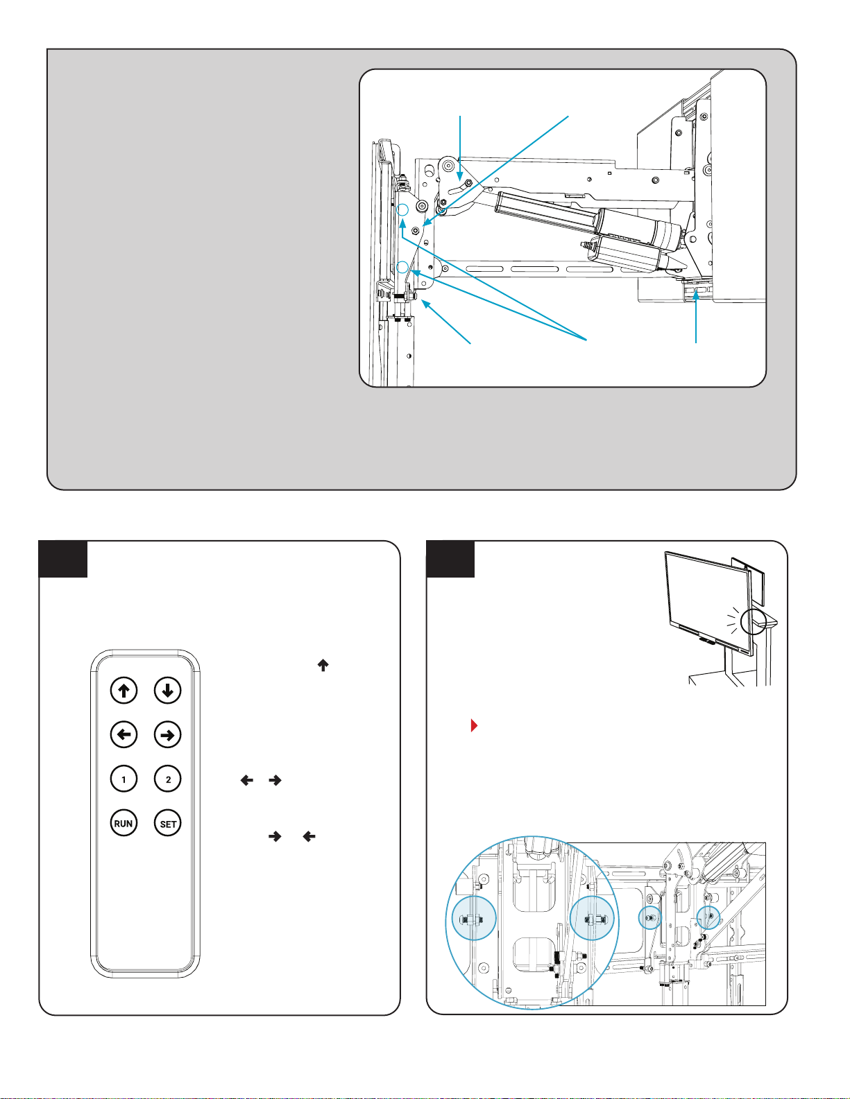
Adjust the Side Swivel Stop
positions, if necessary.
To keep the TV from bumping the
mantel or wall, loosen the Locknuts
{23} and adjust the Swivel Stop
Screws to the desired stopping left
and right positions. Tighten both
Locknuts after the adjustments
are made. Mechanical Swivel
Stops should be just past the
programmed swivel stop
If a small amount or no swivel is desired, it
may be necessary to remove the Screw and/or
Locknuts and reattach them on the other
side of the Swivel Bracket.
NOTE: To better access swivel stop
adjustments screws swivel the mount to the
left or right to gain better access.
Programming Left/Right Stop
If the mount would swivel into the Mantel or some
other object in the bottom position. You can easily
reduce the right and left swivel limits so that the
mount cannot move past them.
5.2
1. Press Run then to
calibrate (Mount Should
move all of the way to the
Top Position).
2. Drive mount to the
Bottom Position
3. Press and hold
or to swivel
mount as far as wanted
4. Press Set.
5. Press or .
6. Press/Hold Set for 4 to 8
Seconds.
7. Check it was correctly
done by trying to move the
mount past set swivel.
Centering Cam
Top Tilt Adjust
Swivel Hardstop
Note: To delete the swivel soft stop
follow steps 3 to 6 but hold the set
button for more than 10 seconds
in step 6
MM815 Installation Instructions
18
5.3
Make Post-Leveling adjustments, if necessary.
Place a level on top of the TV while it’s in the UP position.
If it’s level, the installation is complete! If not, slightly
loosen all four Leveling Screws {15} and rotate the TV
until it’s level and then tighten all the Screws.
5.6
Top Position Tilt Fine Adjustment
TV Tilt in the Top Position can be ne tuned:
1. Drive the Mount to the Topmost Position to check Tilt
2. Drive the Mount down to Access Adjustment Screws
3. Adjustments must be done the same on each side of
the mount
4. Loosen the Lock Nuts
5. Adjust Tilt Adjustment Screws
6. Tighten (Clockwise) to tilt TV down
7. Loosen (Counterclockwise) to tilt TV up
8. Check the settings are the same on both sides
9. Drive Mount to Topmost Position to check Tilt
10. Repeat steps 2-9 until satised
11. Tighten Lock Nuts
5.5
Bottom and Out Tilt Adjustment.
To adjust the tilt in all positions besides the Top Position.
1. Adjust Tilt Adjustment Screw with a 10mm Wrench.
•Tighten (Clockwise) to tilt TV up
•Loosen (Counterclockwise) to tilt TV down
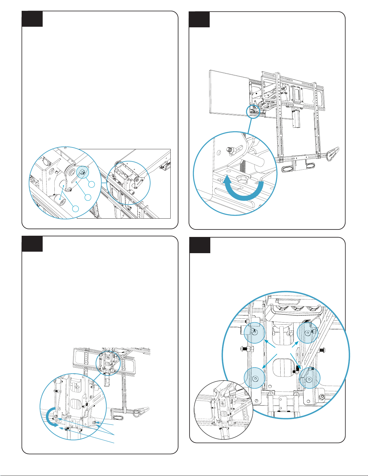
5.4
5.3
Centering Cam Adjust. (OPTIONAL)
A.) Cam Nut B.) Centering Cam C.) Cam Contact Rollers
A
B
C
Bottom and Out Tilt
Adjustment Screw
Tighten screw for
more UP tilt.
Locknut
Top Tilt
Adjustment Screw
Loosen Screw
for More Up Tilt
{15} x4
Centering Cam Adjustment.
The Centering Cam automatically swivels the TV to
center while raising to avoid permanent obstacles.
Out of the Box they are set for max protection, to get
more possible swivel follow below steps.
Warning: ensure Cams are set to avoid damage.
Steps to Set Cam:
1. Move TV to Out Position.
2. Swivel TV so that it is near the wall or mantel.
3. Swing Centering Cam forward until Cam Rollers
Contact.
4. Tighten Cam Nut.
5. Repeat on other side.
6. Swivel the TV and Hold the UP button to ensure it is
set so that the TV can swivel as much as possible in
either direction without it hitting.

19
5.9
Paint the Wall Covers {29} if desired.
5.8
Attach the eight Wall Cover Clips to the wall frame as
shown below. These will be used to attach the adhesive
Velcro strips that hold the wall covers to the wall frame.
Install the Wall Covers using the included adhesive Velcro
strips.
Attach the Hook {25} and Loop {26} strips together onto
the Wall Cover Clips, and then press the Wall Covers into
the correct position onto the Wall Plate. This will properly
align the velcro onto the Wall Covers.
5.10
Hook and Loop Together
5.7
Set Memory Position
To Set Positions 1, 2. There are 2 settable Positions
which can be set.
1. Drive the mount to the
desired Position.
2. Press Set
3. Press the Memory
(Button 1 or 2) Button
within 3 seconds
Quick Note:
To return mount to the
home position press:
Run then arrow.
This will Auto-Swivel
and move mount to
the topmost position.
MM815 Installation Instructions
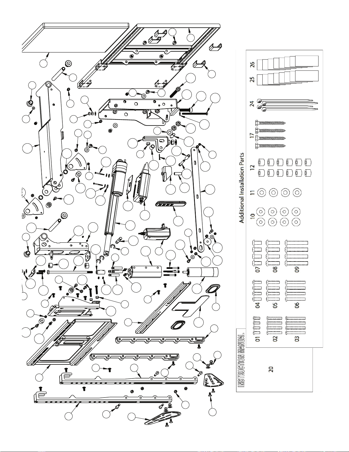
20
201
202
204
205
30
31
63
49
52
57
219
203
206
207
208
209
210
214
212
213
211
215
216
217
220
221
222
223
224
218
227
228
55
252
253
268
267
82
255
253
85 261
23
255
80
266
82
81
11
23
259
264
262
16
23
18
31
33
84
81
87
85
23
11
14
80
60
82
261
226
86
260
85
15
23
15
15
85
256
257
14
261273
89
229
231
10
269
230
272
88
252
32270
271
14
15
18
265
85
Other MantelMount TV Mount manuals

MantelMount
MantelMount MM750 User manual

MantelMount
MantelMount MM340 User manual

MantelMount
MantelMount MM440 User manual

MantelMount
MantelMount MM720 User manual

MantelMount
MantelMount MM700 User manual

MantelMount
MantelMount MM340 Assembly instructions

MantelMount
MantelMount MM860 User manual

MantelMount
MantelMount MM710 User manual

MantelMount
MantelMount MM540 User manual

MantelMount
MantelMount MM860 User manual


