Manzanita Micro PFC-50 User manual

PFC-50 & PFC-75
Charger
Owner’s Manual
Rev 2.1
©2012 Manzanita Micro LLC
The information date is: 02/10/2012
1

CONTENTS
GENERAL OVERVIEW………………………………………………………5
KEY FEATURES LIST………………………………………………………. 6
DIMENSIONS AND SPECIFICATIONS…………………………………… 7
CHARGER OPERATION……………………………………………………. 8
- Photo o Charger Face With Callouts…………………………………. 8
- Volts Trim ~ Adjusting the Peak Charging Voltage Limit………….. 9-10
- Reg Bus Port ~ Basic In o……………………………………………….. 11
- Descriptions o Panel LED Indicators………………………………… 11-12
- Dip Switches……………………………………………………………….. 13
WIRING YOUR MANZANITA MICRO CHARGER……………………….. 14
- Connecting the Charger to the Battery Pack………………………… 14
- Connecting the Charger to the Wall…………………………………… 17
- PFC50 Wiring………………………………………………………………. 14
- PFC75 Wiring………………………………………………………………. 16
- Running Your PFC Charger on DC instead o AC…………………... 19
- 120V Standard Adapter Drawing or PFC50 & PFC75……………….20
- Reg Bus Wiring & Pin-out In o………………………………………….. 21
- Reg Bus Cable Construction……………………………..……………...22
- New 8A Control Board Additional Features…………………………...24-25
- AC Line Power Meter Options………………………………….………...26
CONTACTING MANZANITA MICRO....………………………….………...27
2

READ THIS FIRST!
ADDITIONAL NOTES AND PRODUCT MANUALS AVAILABLE AT: www.manzanitamicro.com
CAUTION: Your PFC-Charger uses High Voltage DC and AC electricity.
The chargers have been designed to be adaptable or use with many di erent battery types and
voltages. It is the responsibility o the end user to properly set up the charger making necessary
adjustments so that it can work with their unique system. With such lexibility, the charger is intended
to be able to be con igured or use in various experimental applications and Manzanita Micro LLC and
its employees, contractors and a iliates cannot be responsible or any damages due to any Manzanita
Micro product that has been set up by the end user. There are too many variables out o Manzanita
Micro's control. It is entirely the responsibility o the end user to make sure that they are competent to
work with potentially lethal voltages and that they have a solid understanding o how to sa ely
integrate the Manzanita Micro product(s) into their application.
The in ormation contained in this warning and in the product manuals is intended to be used as a
guide to better amiliarize onesel with the product(s) but Manzanita Micro has no control over how the
in ormation will be used or not used and cannot possibly oresee all possible con igurations that a
user may come up with.
•Do not work on the PFC-Charger or attempt to use one i you are not quali ied
•Observe the owner’s manual procedures and cautions
•Avoid working on an electric vehicle while it’s charging
•ALWAYS assume that high voltage is present
•Use electrical tape or another suitable insulator to cover all exposed high voltage connection
points and also cover metal tools to reduce the likelihood o the tool completing a current path
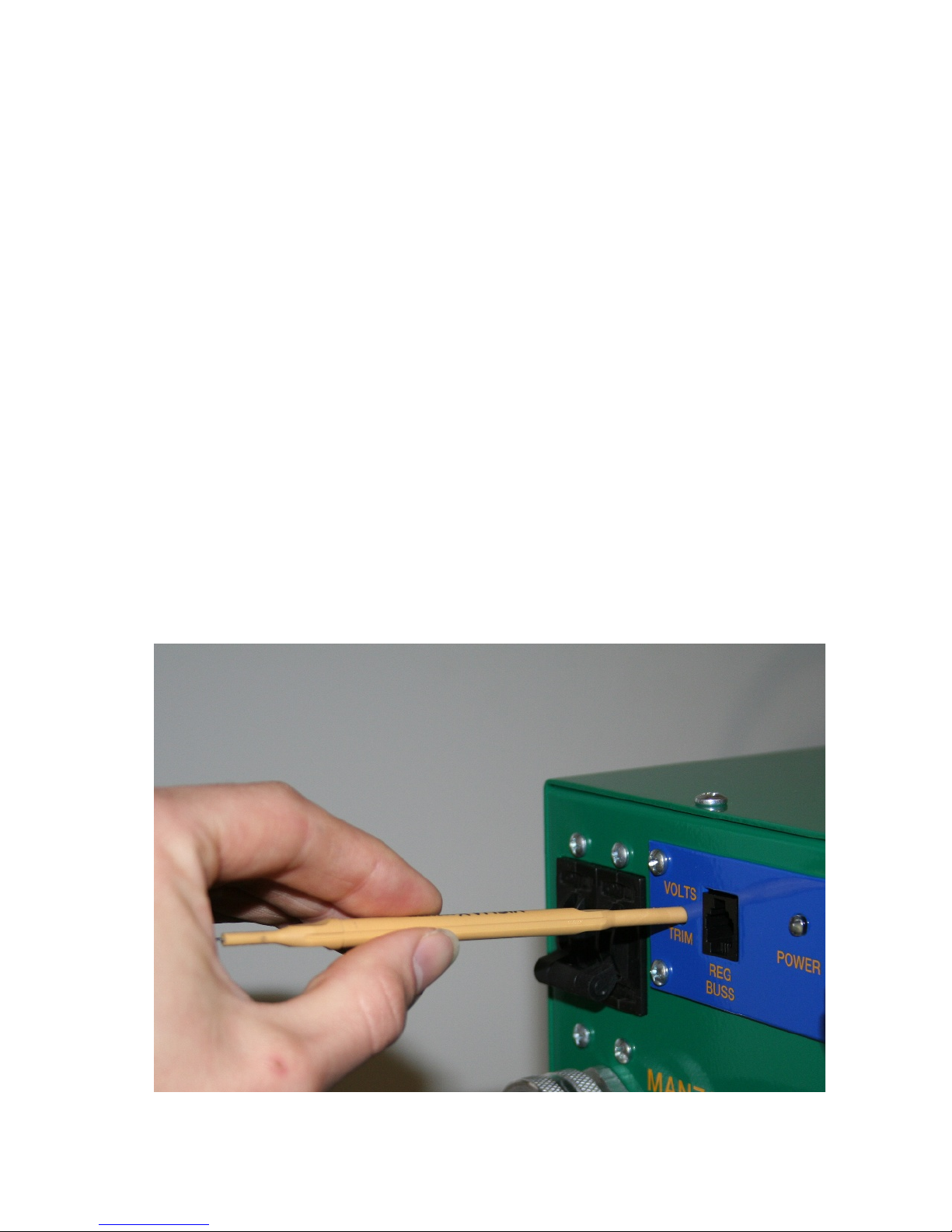
•DO NOT USE A CONDUCTIVE METAL SCREW DRIVER TO ADJUST THE VOLTS TRIM ON YOUR
CHARGER!
•When using a Manzanita Micro BMS with older charger models the Regbus GND return line is
NOT ISOLATED FROM MAIN BATTERY PACK NEGATIVE! Never touch or create a path rom
the regbus conductors to any battery in the pack or serious shock could occur!
•Disconnect all other non-isolated chargers rom the battery pack and rom line current
•Make sure there is NO PATH TO GROUND or the vehicle chassis rom any portion o the main
battery pack.
•Make sure the polarity is correct BEFORE you hook the battery pack to the charger cable.
•Make sure the area around and above the workplace is clean and dry
•Do not compress or set heavy objects on the charger. De orming the case can result in shorting
the internal circuit boards to the case.
•DO NOT operate this charger unloaded! A battery pack must always be plugged in to the DC
output plug rom the charger i it is turned on!
FAILURE TO HEED THESE WARNINGS AS WELL AS THE BATTERY WARNINGS ON THE BACK OF
THIS SHEET MAY RESULT IN PHYSICAL INJURY, DEATH, OR DAMAGE TO YOUR CHARGER, BMS OR
OTHER EQUIPMENT WHICH WILL NOT BE COVERED UNDER YOUR WARRANTY.
IT IS RISKY TO PLUG ANY BATTERY CHARGER INCLUDING MANZANITA MICRO CHARGERS INTO
GENERATORS. MANY GENERATORS ESPECIALLY THE LESS EXPENSIVE GENSETS DO NOT HAVE A
CLEAN, WELL REGULATED, PREDICTABLE OUTPUT AND THEY CAN CREATE HIGH VOLTAGE
SPIKES WHICH CAN DAMAGE COMPONENTS IN THE CHARGER. SOME CUSTOMERS HAVE HAD
SUCCESS WITH HIGH END PURE SINE WAVE COMPUTER GRADE GENERATORS BUT MANZANITA
MICRO CANNOT RECOMMEND A SPECIFIC MODEL AT THIS TIME AND CANNOT BE RESPONSIBLE
FOR ANY DAMAGE DUE TO GENERATORS OR OTHER POWER SOURCE PROBLEMS.
3

BATTERY NOTES!
CAUTION: Your PFC-Charger can output over 400 volts DC and many thousands o watts o electrical
power! It is imperative that the end user have a clear understanding o how to sa ely charge their
particular battery!
Manzanita Micro sells very lexible charging systems that can be used with almost any type o battery.
Manzanita Micro chargers are used in all sorts o applications. Manzanita Micro LLC cannot be held
responsible or any problems arising rom the improper use o the charger or BMS with a battery pack
or other storage device.
FAILURE TO OPERATE BATTERIES OR OTHER ENERGY STORAGE DEVICES WITHIN THEIR SAFE
DESIGN PARAMETERS CAN RESULT IN CATASTROPHIC FAILURES INCLUDING BUT NOT LIMITED TO
FIRE, EXPLOSION, TOXIC FUMES, EXCESSIVE HEAT, THE RELEASE OF CAUSTIC OR POISONOUS
MATERIALS, PHYSICAL DEFORMATION AND VARIOUS OTHER POTENTIALLY LETHAL SITUATIONS.
ALWAYS WEAR EYE PROTECTION AND OTHER PROPER PERSONAL PROTECTIVE EQUIPMENT
WHEN WORKING AROUND BATTERIES. UNDERSTAND THE SAFE HANDLING INSTRUCTIONS AND
IMPORTANT SPECIFICATIONS OF YOUR PARTICULAR BATTERY PACK OR ENERGY STORAGE
DEVICE! IF EVER IN DOUBT, CONTACT THE BATTERY MANUFACTURER!
NEVER ALLOW MORE THAN ONE PERSON TO WORK ON THE SAME HIGH VOLTAGE SYSTEM OR
BATTERY PACK AT THE SAME TIME. IF TWO OR MORE PEOPLE ARE TOUCHING PARTS OF THE
SYSTEM IT IS EASIER TO COMPLETE A CIRCUIT AND CAUSE ELECTROCUTION. WHILE MULTIPLE
PEOPLE SHOULD NEVER WORK ON THE SAME SYSTEM, IT IS ADVISABLE TO HAVE MORE THAN
ONE PERSON NEAR BY WHENEVER ONE PERSON IS WORKING WITH HIGH VOLTAGE.
NEVER TOUCH ANYBODY WHILE THEY ARE WORKING ON A HIGH VOLTAGE SYSTEM OR BATTERY
PACK! IF SOMEONE IS GETTING SHOCKED AND CANNOT LET GO OF THE ELECTRICAL SOURCE,
THE EXTRA PERSON CAN SAFELY DISCONNECT THE ELECTRICAL SUPPLY AND/OR GET HELP. IF IT
IS NOT POSSIBLE TO DISCONNECT THE SUPPLY, AND IF PROPERLY INSULATED EQUIPMENT IS
AVAILABLE THEN THE EXTRA PERSON MAY USE A DEVICE SUCH AS AN INSULATED HUMAN HOOK
TO PULL THE PERSON BEING SHOCKED AWAY FROM THE ELECTRICITY. NEVER EVER TOUCH
SOMEONE WHO IS BEING SHOCKED!
Manzanita Micro chargers are very power ul. Do not exceed the sa e charging rates as speci ied by
your particular battery manu acturer!
Manzanita Micro chargers are capable o outputting any charging voltage rom 12 to 450 volts DC. It is
up to the end user to understand the sa e voltage range or their particular battery, cell, battery pack or
other energy storage device. Do not exceed the peak charging voltage given by the battery
manu acturer. Care ully read the Manzanita Micro Owner’s Manual(s) or your particular product(s). For
chargers, it is essential to understand how to properly set the peak charging limit using the volts trim
potentiometer. For BMS (Battery Management Systems) it is imperative that the user makes sure that
the BMS is properly set to match the sa e and appropriate parameters or their particular make and
model o battery.
Ask the battery manu acturer or all parameters on how to sa ely charge their batteries and do not use
any charger or BMS i you cannot properly tune the equipment to meet those speci ications.
4

PFC-50 / 75 BATTERY
CHARGER MANUAL
Rev 2.1
General Overview
The Manzanita Micro PFC chargers are a unique grou of owerful, efficient battery
chargers. The chargers will run off any voltage from 100 u to 240 volts AC. The
chargers can be set to run automatically when lugged in, yet they also have far
more user adjustable functions than other electric vehicle chargers. Every model is
user adjustable to charge batteries from 12 to 450 Volts DC. The PFC-50, PFC-50B
and PFC-75 are all ower factor corrected. The PFC-75 comes standard with an AC
in ut current dis lay and rear anel mount Anderson Power Pole connections. With
so much flexibility and models from 20 to 75am s, your PFC charger may be the
last charger you ever need to buy.
Speed and E iciency
The essential ingredient for fast recharge times is to deliver high ower to the
battery. The key to olite o ortunity charging is to be able to share outlets with
other equi ment and make efficient use of limited current. The Manzanita Micro
PFC line of chargers has an adjustable current throttle knob to allow the chargers to
be turned down to o erate on very limited ower sources. Even the venerable PFC-
75 can easily run at reduced out ut from a 110 volt source. Efficiency and ower
factor are both better than 0.9.
What does the PFC mean?
In the Manzanita Micro chargers PFC stands for Power Factor Corrected. This
means that current and voltage are drawn in unity, (ie: current is drawn with unity to
the incoming line voltage).
5

PFC-50/75 SERIES
CHARGER FEATURES
•Power Factor Corrected
•Every charger easily runs on any single hase AC voltage from 100 to 240V
•Easy ‘Am s’ adjustment knob allows users to quick-tune the charger to ull
maximum am s out of whatever it is lugged into
•User adjustable eak charge voltage allows users to ada t charger to any
battery voltage from 12 to 450 volts
•U to 18,000 watts of ower from a unit that weighs less than 50 lbs (22kg)
•Reg bus ort for easy integration with Manzanita Micro BMS (also com atible
with other Battery Management Systems)
•Self regulating thermal rotection
•Active variable s eed fan cooling
•In ut line current meter o tion
•Rear anel mount Anderson Power Pole I/O connections on PFC-75 (this is
o tional for the PFC-50 or PFC-50B)
•Adjustable absor tion hase (end of charge) timer function
•Ability to enable auto restart mode
•Ability to enable timed charging mode
•Float charge o tion ossible with new 8A control board
6

Dimensions and Speci ications
The PFC-50 and 75 series chargers weigh a roximately 42 ounds (19 kg)
The outermost dimensions including foot flanges and front am s knob are
a roximately 22” L x 12.5” W x 7” H (559mm x 318mm x 177mm)
Allow at least 25” total length (635mm) to include the ower cables
In ut Voltage Range : 100 to 240VAC 40-80Hz com uter grade ure sine wave
Out ut Voltage Range : 12 to 450VDC ( +/- 1 volt )
O erating Tem Range : -20° F to +120° F ( -28.8° C to +48.8° C )
Power Consum tion : U to 12.0kW ~ PFC-50 and PFC-50B / 18.0kW ~ PFC-75
The 50 in PFC-50 is indicative of the number of am s that the charger is rated to
draw from the AC line. A PFC-75 can draw u to 75 am s. Unlike some other
chargers, this is the rated continuous load and all units are thoroughly tested to their
rated limits before leaving Manzanita Micro. The PFC-75 model includes a current
meter on the front which dis lays the amount of current (am s) that the charger is
drawing from the AC line. This allows the user to tune the charger recisely for the
maximum allowable am s for the outlet they are lugged into.
The charger can be mounted in any orientation as long as it has adequate airflow
and is rotected from sucking in moisture and debris. All chargers are designed to
automatically cut back current when they exceed their tem erature limits. If the
yellow limits light starts blinking and ower is reduced, it is likely more airflow is
needed. The fans ush the air out through the front of the charger therefore,
mounting the unit such that the control face is ointing u ward this is robably the
most efficient since heat rises. It is im ortant to use ro erly sized bolts for all four
mounting holes in order to mount the unit. Grade 5 or Grade 8 fasteners are the
7

best and stainless steel or other quality lating is referable to decrease corrosion.
Charger Operation
figure 02. Charger Layout (see final section for new 8A layout)
Turning the Charger On and O
There is an ON/OFF Breaker to the left of the blue user control anel at the to of
the charger. This breaker is the main switch to turn the charger on or off. If ever
there is a concern while charging first shut off this breaker switch.
NOTICE! DO NOT un lug the Anderson connectors (DC line) from your charger
while it is charging! If the battery ack is disconnected while the charger is utting
out ower the charger can be damaged. Failure to heed these warnings may
result in signi icant internal damage to the charger which is not covered under
your warranty!
8

User Control Panel
The user interface anel is the long blue anel with yellow text near the to of the
PFC charger. The main things most users need to be concerned with are the LED
indicators, the VOLTS TRIM and the adjustable AMPS knob. Below are
ex lanations of each feature in order from left to right. Refer to figure 02 for s ecific
locations.
“VOLTS TRIM”
This controls the eak DC voltage ceiling that the charger will allow the batteries to
reach before limiting the current. Unless s ecified otherwise, the voltage limit is
s ecifically calibrated and set by Manzanita Micro to 191 Volts (for a 156V nominal
ack.) In the event that adjustment is desired, lease follow the instructions below.
Starting in 2010, a s ecial insulated screw driver for adjusting the volts trim is
shi ed with each new Manzanita PFC charger.
NOTICE! Always use an a ro riately sized insulated screw driver when adjusting
the voltage trim otentiometer. Suitable drivers are available for urchase from
Manzanita Micro or other electronics com onents manufacturers. (Mouser art #:
594-8T000, Vishay/S ectrol Adjust Tool, www.mouser.com)
figure 03. Ad ustment Tool # 008T000
NOTE: If the battery ack is es ecially cold for any reason such as outdoors in a
cold season or climate, the eak charging voltage threshold may need to be raised
in order to assure a com lete charge. This is es ecially true for lead acid batteries.
Many users turn the volts trim to the absolute maximum safe level for the batteries
during the winter and then back down to normal during the summer months. Always
consult your battery manufacturer for information on the eak “fully charged” voltage
s ecifications and how they change based on tem erature.
NOTE: The eak voltage regulation set oint on a Manzanita Micro charger is
accurate to within 5 volts or less. Follow the “Volts Trim Calibration” instructions
below and make the initial adjustment with the am s knob com letely down so that
no current is flowing. Gradually turn u the am s knob and nudge the volts trim
otentiometer u accordingly. Use caution on the first charge cycle and make sure
to check that the oint at which the charger volts trim limit is reached is really the
correct voltage for your s ecific batteries.
9

VOLTS TRIM CALIBRATION:
Final tuning is best accom lished when the battery ack is fully charged. The lower
the state of charge, the more the user will need to monitor and adjust the unit during
the first charge cycle.
1. Turn the am s knob all the way down (full counterclockwise).
2. Make sure the charger is lugged into the battery ack and that there are no o en breakers or
o en fuses in the DC battery circuit.
3. With the charger’s AC breaker switch in the OFF osition, lug the charger into the AC ower
outlet.
4. Now turn ON the charger’s AC breaker switch. The fans should come on.
5. Using an a ro riate insulated screw driver, stick it into the VOLTS TRIM access hole (see
figure 04) and turn the internal adjustment otentiometer until you find the threshold where the
yellow LIMITS LED changes state. If the yellow LED is off, turn the trim ot counterclockwise
to get it to go on. If the yellow LED is on, turn the trim ot clockwise to get it to go off. Once
you find the threshold where the LED changes states, the cutoff voltage is set to the actual
battery voltage and the charger will not charge the ack above this voltage. Therefore, when
you are ready to charge you will need to turn the trim ot clockwise to raise this voltage
ceiling. Then turn the AMPS knob u until you can ut the amount of am s you want into the
battery ack while not letting the batteries go over their eak voltage limit according to their
manufacturer’s data.
While charging, when the battery ack voltage hits the eak limit the yellow LIMITS
LED will come on along with the flashing blue TIMER LED.
figure 04. VOLTS TRIM Ad ustment
10

“REG BUS”
This is the 6 in RJ jack where the BMS communication line lugs into the charger.
This ort allows the individual battery regulators to communicate with the charger.
For more information on the s ecific reg bus ins refer to the “Reg Bus Wiring”
section later in this manual.
NOTICE! If your vehicle is equi ed with a Battery Management System, ensure
that the reg bus data cable is fully lugged into the charger whenever the vehicle is
charging. The communication data cables are hooked to the regulators in a daisy
chain fashion. Make sure that each of the smaller data cables are all lugged in
where they should be before charging. I there is an unplugged portion o the reg
bus, the charger cannot communicate with the regs and this could lead to a
potentially damaging situation i there is an un-matched battery cell in the
pack! The RJ connectors are similar to hone cord connectors and they are
designed to sna into lace and stay connected. If a cable is disconnected insure
that it is fully reconnected. An audible *click* should be heard when the RJ lug is
fully inserted and it should not be able to be ulled out without first inching the
small lastic tab underneath the lug. For more information on reg bus cables refer
to the “Reg Bus Wiring” section later in this manual.
“POWER” - Green LED
The bright green POWER LED indicates when the charger is on. In ut ower is
being su lied to the unit and the main breaker is in the ON osition.
“WARN” - Red LED
The red WARN LED should blink briefly when the charger is first owered u and
then remain off for the duration of the charge. If this indicator stays on, turn down
the AMPS knob immediately, turn off the charger’s breaker switch and consult
Manzanita Micro or a qualified service technician. This LED could indicate an over
voltage or over tem erature condition. It could also be indicative of an o en circuit
condition in the ack. Turn down the AMPS knob and check to make sure there is
no o en circuit condition in the battery ack. Check the DC ower connection
(Battery Pack side) to ensure that it is tightly connected and look for other
disconnected battery cables. If the charger will not work and the circuit is com lete,
contact Manzanita Micro.
NOTICE! DO NOT let the charger try to ut current into the battery ack if there is
an o en circuit condition in the circuit. Never un lug the DC (battery ack side)
Anderson connectors from your charger while it is charging! If the battery ack is
disconnected while the charger is utting out ower the charger can be damaged.
Failure to heed these warnings may result in signi icant internal damage to the
charger which is not covered under your warranty!
11

“AMPS” Knob
The AMPS knob allows the user to adjust how much current the charger will move.
If the vehicle is always lugged in to the same circuit this shouldn’t need any
adjusting but if the user were to have it set at 35 am s and then lug into a 15 am
120V outlet it will quickly o en a circuit breaker or fuse on the AC line. The vehicle
o erator may wish to adjust this knob when the charger is lugged in to a ublic
outlet es ecially if there is no easy access to the electrical anel for that circuit.
Additionally, the user might need to turn down the charger if there are other loads on
the branch circuit (exam le: A stereo and a com uter are running on the same 15
am circuit). If using a charger equi ed with the anel mount meter, the user can
check the digital current meter on the front of the PFC unit and see exactly how
many am s the charger is drawing from the wall.
“LIMITS” - Yellow LED
The yellow LIMITS LED indicates that the charger has reached its eak voltage limit.
This should ha en only at the end of the charge cycle when all the batteries are
fully charged. The LIMITS indicator should be accom anied by the blinking blue
TIMER LED which indicates that the charger is in current cutback mode and the
timer is counting down to the end of charge.
If the yellow LIMITS LED is blinking, then it is indicating that there is an over
tem erature condition and the charger is in thermal cutback mode.
NOTE: When using regulators, the blue TIMER LED will often come on before the
LIMITS LED because the battery regulators let the charger know when the batteries
are getting full before the voltage limit is reached. If the LIMITS light is coming on
frequently or before most of the regs are blinking, this could be indicative of a few
batteries whose voltages are getting too high. It could also mean that someone has
im ro erly adjusted the VOLTS TRIM. Consult your battery regulator user’s manual
or recalibrate the VOLTS TRIM setting on the charger.
“TIMER” - Blue LED
The blue TIMER LED indicates that the charge is com lete or near com letion. If it
is flashing it means that charging is almost finished and the charger is backing off
the current and counting down the timeout timer. When the blue LED is steady, it
means that the timeout timer has ended and the charger has finished charging the
ack. At this oint the charger should be utting out no ower and drawing less than
an am from the in ut line.
“TIMER ADJ”
This stands for timer adjustment. This is a small 16 osition rotary switch which
allows the user to adjust the amount of time that the charger takes in constant
voltage mode, while cutting back current at the end of a charge cycle before it shuts
off com letely.
12

If the switch is at ‘0’ then the timer will time out instantly - do not use this setting. (‘0’
is the 3-o-clock osition when viewed from the front). If the switch is at ‘1’ it will go
for 15 minutes before com letely cutting back ower. Each additional tick after ‘1’
adds 10 more minutes to the charge cutback time. Turning the switch clockwise all
the way around to the 2:30 osition will give the maximum amount of time.
To reset the timer after it has started turn off the
ower to the charger and then turn the ower on
again.
“DIP SWITCHES”
The red and white di switch module is on the u er right end of the charger. This is
a bank of 8 switches and they are numbered starting with #1 on the far right.
NOTICE! Adjusting these switches can cause the charger to erform in an
undesirable manner. Please be sure you understand these switch features before
changing them. Pull switches down to turn them on. Figure 02 shows the factory
reset ositions. NEVER CHANGE DIP SWITCH #4! IT MUST REMAIN ON!
Di Switch Guide:
1. Engages timer at eak voltage limit set oint. This switch should be ON.
If the ack dro s below the eak voltage limit, the timer will turn off again.
2. Starts timer as soon as the charger is turned on. This can be used for timed
charging. This switch should be OFF.
3. Starts timer when the reg bus commands. This switch should be ON.
If the reg bus sto s sending the signal, the timer will turn off again.
4. Future feature switch. THIS SWITCH MUST A WAYS BE ON!
5. Future low battery detection feature. This switch should be OFF.
6. AGM battery equalization. When using Mk2 series battery regulators, this will
allow the batteries to climb to a slightly higher voltage for equalization at the end
of charge. It also commands the yellow LEDs on each reg to turn on. This
switch should be OFF.
7. When the high voltage limit is set the charger sto s moving ower immediately.
This should be OFF.
8. Auto restart function. This allows the charger to restart charging when the
battery ack reaches a certain set low voltage oint. This switch should be OFF
unless using the auto restart feature.
NOTE: Di switch #6 can be useful if you have battery regulators because you can
momentarily switch it on and the yellow lights on all the regs should come on. If any
don’t, you can use this feature to narrow down which regs are not communicating
with the charger. This feature does not work with the old LT-5 single cell regulators.
13

NOTE: In mid 2010, a new 4 in RJ rece tacle was added to the front of the charger
allowing for various reset voltage and current levels. For more information lease
refer to the 8A Control Board section at the end of this manual.
Wiring your Manzanita Micro Charger
A PFC-50 or PFC-50B charger built before 2011 should have two main ower
cables coming out of the front of the case (as shown in figure 02). The to cable is
for the incoming ower (usually AC from a wall outlet) and the lower cable is the
charger’s DC out ut.
All PFC-75 chargers and all PFC-50 and PFC-50B models roduced after 2011
should have anel mount Anderson Power Pole connections on the rear side
instead of the older style front mounted ower cables.
Connecting the Charger to the Battery Pack
PFC-50 Battery Pack to Charger Wiring
For rear mount connections please re er to the PFC-75 wiring section that
ollows this one. Looking at the front of a re-2011 PFC-50 or PFC-50B charger,
you will see that the lower DC out ut cable has a Blue SB-175 Anderson connector
on it. This SB-175 connector is easily obtainable and we recommend that you leave
this lug on the cord. The SB-175 connector has clearly marked ositive and
negative sides. Of the three DC wires coming out of the front of the charger white is
ositive, black is negative and green is an o tional vehicle chassis ground
connection. Measure the distance from your most ositive battery terminal to your
PFC charger’s SB-175 connector. Cut a #4 AWG or thicker cable to the a ro riate
length and solder or crim the a ro riate size SB-175 in onto one end of the
cable. It is recommended that you use bright orange cable with a good insulation
and a voltage rating in excess of your fully charged ack voltage. (Bright orange
Carol brand Su er Vu-Tron welding cable is an excellent solution.) Place red heat
shrink or red electrical ta e around the cable near each end to clearly designate it
as the ositive cable and then using a matching blue SB-175 connector, ush the
SB-175 in end of the ositive cable into the ositive side of the SB-175 until it
clicks and locks in lace.
Next, measure the distance from your most negative battery terminal to your PFC
charger’s SB-175 connector. Cut a #4 AWG or thicker cable to the a ro riate
length and solder or crim the a ro riate size SB-175 in onto one end of this
cable. Place black heat shrink or black electrical ta e around the cable near each
end to clearly designate it as the negative cable and then ush the SB-175 in end
of this negative cable into the negative side of the SB-175 until it clicks and locks in
lace.
14

figure 05 : Example DC Power Cables
Now you should have a blue SB-175 connector with a ositive and negative wire
coming out. (See figure 05) Use the a ro riate size lug or connector for your
battery terminal and crim or solder it onto the other end of each cable. In order to
reduce the likelihood of cable damage from corrosion, it is recommended to use a
closed end tinned co er lug as o osed to an o en end lug. Place the a ro riate
color (red or black) adhesive lined heat shrink over the joint between the lug and the
cable insulation to finish the connection. Now connect the ositive cable to the most
ositive terminal of the battery ack. Connect the negative cable to the most
negative terminal of the battery ack.
Use a digital volt meter to double check that the olarity in the lug is correct and
then lug the battery ack SB-175 into the DC out ut SB-175 coming from the PFC
charger. Now the charger is connected to the ack and you are ready to hook u the
charger’s in ut ower.
figure 06: PFC-50 Plugs
15

PFC-75 Pack Wiring
Looking at the back of a PFC-75 charger or ost 2011 PFC-50, you will see that
there are five individual Anderson Power Pole connectors. There is a black and a
red one next to each other on the to which is the DC out ut end of the charger. For
your convenience a red and a black Power Pole connector have been included with
your PFC-75. The red connector is for battery ositive and the black connector is for
battery negative. Measure the distance from your most ositive battery terminal to
your PFC charger’s red Power Pole connector. Cut a #1 AWG or thicker cable to the
a ro riate length and solder or crim the a ro riate size Power Pole in onto one
end of the cable. It is recommended that you use bright orange cable with a good
insulation and a voltage rating in excess of your fully charged ack voltage. (Bright
orange Carol brand Su er Vu-Tron welding cable is an excellent solution.) Place red
heat shrink or red electrical ta e around the cable near each end to clearly
designate it as the ositive cable and then ush the in into the back of the red
Power Pole connector until it clicks and locks in lace.
Next, measure the distance from your most negative battery terminal to your PFC
charger’s black Power Pole connector. Cut a #1 AWG or thicker cable to the
a ro riate length and solder or crim the a ro riate size Power Pole in onto one
end of the cable. It is recommended that you use bright orange cable with a good
insulation and a voltage rating in excess of your fully charged ack voltage. (Bright
orange Carol brand Su er Vu-Tron welding cable is an excellent solution.) Place
black heat shrink or black electrical ta e around the cable near each end to clearly
designate it as the negative cable and then ush the in into the back of the black
Power Pole connector until it clicks and locks in lace. (See figure 05)
Use a digital volt meter to double check that the olarity in the lug is correct and
then lug the battery ack Power Pole connectors into their res ective DC out ut
Power Pole mates coming from the PFC charger. Now the charger is connected to
the ack and you are ready to hook u the charger’s in ut ower.
16

figure 07 Rear Power Pole Charger Connections
Connecting the Charger to the Wall
Looking at the front of a re-2011 PFC-50 the charger you will see that the to cable
is labeled AC and it is the incoming ower for the charger. Looking at the rear of a
PFC-75 or other late model charger you will see 3 Anderson Power Pole connectors
beneath the two DC out ut connectors. A great feature of the Manzanita Micro PFC
line of chargers is that they are ca able of o erating easily when owered from
110,120, 208, 220, 230 or 240 volts of single hase AC ower.
NOTE: PFC-50, 50B, and 75 chargers must be modified to run off of DC. For more
information on running your charger from a DC in ut ower source see the “Running
Your PFC Charger on DC instead of AC” section later in this manual.
Ohm’s law states that Volts x Amps = Watts of ower and there are a certain
number of “Watt Hours” stored in your battery ack and available to ower your
electric vehicle. Based on the VxA=Watts equation it is easy to see that more volts
or am s (or both) equates to more total watts which means more electrical ower
moving thus faster charging.
Your Manzanita Micro PFC charger can be owered by any in ut voltage within the
100-240V range and there is no voltage adjustment or switches to move when
17

changing between outlets of different voltages. The only thing which may need
adjustment on the charger is the big “Am s” knob on the front. Turn this knob u or
down de ending on the am erage available from the outlet. With the “Am s” knob
in the most clockwise osition a PFC-50 can draw u to 50 am s and a PFC-75 can
draw u to 75 am s.
EXAMPLE: A PFC-50 lugged into a standard 120V outlet at 15 am s would be
able to draw about 1,800 watts (120x15 = 1,800). The same PFC-50 lugged into a
240V outlet at 50 am s could draw about 12,000 watts, meaning a charge time that
is over six times faster than in the 120V scenario.
PFC-50 In ut Wiring (For Front In ut Corded Models)
For rear connection PFC-50 models refer to the PFC-75 in ut wiring section below.
Most PFC-50 chargers built before 2011 were shi ed with a NEMA 14-50 on the
AC in ut cable. Please leave this attached and make ada ter cords if you intend to
change what it lugs in to. The 14-50 outlet is very common at RV arks, in homes
for electric ovens and at some ublic charging stations.
To attach the PFC-50’s in ut cable to a common 110/120V three rong 5-15 or 5-20
lug urchase a 14-50 rece tacle and make an ada ter exactly as shown in figure
08. If you wish to make an ada ter cord to connect your PFC-50’s in ut cable to a
220/240V three rong lug (like a NEMA 10-30, 10-40 or 6-50), use a 14-50
rece tacle and sim ly disregard the white wire and the middle straight neutral rong.
Run the green wire to the ground rong and then the red and black wires to either of
the two hot rongs.
The front connection PFC-50 chargers come with a 4 wire AC in ut cable but do
not ever use the White neutral wire or anything. Even though there is a 4-wire
lug on the unit, the white wire should never be connected to anything.
PFC-75 In ut Wiring
The PFC-75 is shi ed with an 3 connector Anderson Power Pole array and 3 black
1 AWG cables for the AC in ut. The other ends of the included connector are to be
wired to an a ro riate 75 am or greater lug. Manzanita Micro recommends a 100
Am in and sleeve style lug. The male end is attached to these 3 in ut cables so
that it can lug into a female twistlock that is bringing the ower from the wall.
NOTE: Extra Power Pole connectors can be urchased for making a second
“Power-Pole-to-male-NEMA-14-50” ada ter. With this configuration the charger
must not be allowed to draw over 50 am s but it makes it easier to lug in at more
locations and still get a decent amount of current. The 14-50 outlet is very common
at RV arks, electric ovens and some ublic charging stations.
To attach the PFC-75’s in ut cable to a common 110/120V three rong 5-15 or 5-20
lug, Manzanita micro recommends urchasing a 14-50 rece tacle and make an
ada ter exactly as shown in figure 08. If you wish to make an ada ter cord to
connect your PFC-50’s in ut cable to a 220/240V three rong lug (like a NEMA 10-
18

30, 10-40 or 6-50), use a 14-50 rece tacle and sim ly disregard the middle straight
neutral rong. Run the green wire to the ground rong and then the white and black
wires to either of the two hot rongs. Since there is no neutral in the older 3 rong
220/240V lugs sim ly disregard the fact that your PFC charger has a 4 rong lug
on it.
Running Your PFC Charger on DC instead o AC
You may have heard that Manzanita Micro chargers can run from both AC and DC
ower. This is true under the right circumstances; in fact the PFC40HM is designed
to run on both AC and DC in the Pi Prius conversion kits.
NOTICE! The Manzanita Micro chargers were really designed to run from an AC
ower source. If you are lanning to run one on DC ower and it is damaged, re air
work will likely NOT BE COVERED UNDER WARRANTY! It should be noted that
the primary on/o circuit breaker on the charger is only AC rated. For this
reason, we recommend installing an appropriate DC rated breaker or use on
the input side when powering any Manzanita charger with DC.
There are two Manzanita Micro PFC charger models which can be run from DC
ower without having to make any internal adjustments to the unit. These unique
models are the standard PFC-20 and the PFC-40HM. Some re-2011 standard
PFC-50 chargers may work as well but check with Manzanita Micro to be sure.
If you are running a charger on DC ower, it is advisable to kee the in ut voltage
between 100 and 390VDC. The lowest voltage that will get the charger to turn on is
about 60VDC. The absolute highest acce table DC in ut voltage is 400V. NEVER
EVER EXCEED THE 400VDC MAXIMUM INPUT VOLTAGE!!
NOTE: The PFC-50B, PFC-75 and newer standard PFC-50 models can be modified
to run on DC. Contact Manzanita Micro for more information if you are really
determined to run a charger from a DC ower source.
19

figure 08. PFC-50 Adapter Wiring
20
This manual suits for next models
1
Table of contents
Other Manzanita Micro Batteries Charger manuals