Maple Systems OMI6700 Series User manual

Your Industrial Control Solutions Source
_____________________
www.maplesystems.com
Maple Systems, Inc. | 808 134th St. SW, Suite 120, Everett, WA 98204 | 425.745.3229
For use with the following:
OMI6707A
OMI6710A
OMI6712A
OMI6715A
OMI Operations Manual
OMI6700 Light Industrial Panel PC Series

OMI Operations Manual: OMI6700 Series 2
OMI Operations Manual: OMI6700 Series 2
TABLE OF CONTENTS
TABLE OF CONTENTS............................................................................................................. 2
COPYRIGHT NOTICE............................................................................................................... 3
WARRANTY.............................................................................................................................. 3
TECHNICAL SUPPORT ............................................................................................................ 3
UNPACKING THE UNIT............................................................................................................ 4
SAFETY PRECAUTIONS .......................................................................................................... 5
DIMENSIONS AND SPECIFICATIONS ..................................................................................... 6
OMI6707A Dimensions .......................................................................................................... 6
OMI6707A Specifications....................................................................................................... 7
OMI6710A Dimensions .......................................................................................................... 8
OMI6710A Specifications....................................................................................................... 9
OMI6712A Dimensions .........................................................................................................10
OMI6712A Specifications......................................................................................................11
OMI6715A Dimensions .........................................................................................................12
OMI6715A Specifications......................................................................................................13
OVERVIEW OF OMI6700 SERIES...........................................................................................14
I/O PORTS............................................................................................................................17
COM1 and COM2: ................................................................................................................17
Line Out: ...............................................................................................................................17
USB: .....................................................................................................................................18
LAN1 and LAN2:...................................................................................................................18
SETTING COM1 FUNCTION....................................................................................................19
VESA MOUNTING....................................................................................................................22
PANEL MOUNTING..................................................................................................................22
OPERATING SYSTEM OPTIONS ............................................................................................23
WONDERWARE / INDUSOFT WEBSTUDIO ON AN OMI6700...............................................23
INSTALLATION OF DRIVERS.......................................................................................... 24
Intel Chipset Driver................................................................................................................24
VGA Driver............................................................................................................................26
LAN Driver ............................................................................................................................28
Audio Driver..........................................................................................................................29
Touch Screen Driver.............................................................................................................30
TOUCH SCREEN.....................................................................................................................32
Touch Screen Calibration......................................................................................................32
Touch Screen Settings..........................................................................................................33
Touch Screen Edge Compensation.......................................................................................34

OMI Operations Manual: OMI6700 Series 3
OMI Operations Manual: OMI6700 Series 3
COPYRIGHT NOTICE
This manual is a publication of Maple Systems, Inc., and is provided for use by its customers
only. The contents of the manual are copyrighted by Maple Systems, Inc.; reproduction in whole
or in part, for use other than in support of Maple Systems equipment, is prohibited without the
specific written permission of Maple Systems.
WARRANTY
Warranty Statements are included with each unit at the time of purchase and are available at
www.maplesystems.com.
TECHNICAL SUPPORT
This manual is designed to provide the necessary information for trouble-free installation and
operation of your new OMI. However, if you need assistance, please contact Maple Systems:
Phone: 425-745-3229
Email: support@maplesystems.com
Web: http://www.maplesystems.com

OMI Operations Manual: OMI6700 Series 4
OMI Operations Manual: OMI6700 Series 4
UNPACKING THE UNIT
Carefully unpack the OMI6700. Check all material in the container against the packing list.
Maple Systems will not accept responsibility for shortages against the packing list unless
notified within 30 days. The equipment and accessories were inspected and tested by Maple
Systems before shipment.
Examine the equipment carefully; if any shipping damage is evident, notify the carrier
immediately. Maple Systems is not responsible for claim negotiations with the carrier.
Save the shipping container and packing material in case the equipment needs to be stored,
returned to Maple Systems, or transported for any reason.
Packing List
OMI6700 Series Light Industrial Panel PC
DC Power Connector (3 pin terminal block)
DC Power adapter with cord
Mounting Clamp Kit
OMI6000 Support DVD
Windows Recovery DVD (for Windows Pro OS only)
OMI Operations Manual: OMI6700 Series 5
OMI Operations Manual: OMI6700 Series 5
SAFETY PRECAUTIONS
Please observe the following precautions when installing the OMI6700 Series Open HMIs.
Failure to comply with these restrictions could result in loss of life, serious personal injury, or
equipment damage.
Warning: Disconnect this equipment from any power before cleaning. Do not
use liquid or spray detergents for cleaning. Use a damp cloth.
Warning: Keep this equipment away from humidity.
Warning: Before applying power the unit make sure the voltage of the power
source is within the input voltage rating of the unit.
Warning: Position the power cord so that people cannot step on it. Do not place
anything over the power cord.
Warning: Never open the equipment and do not operate equipment with its back
cover removed- there are dangerous high voltages present inside. For safety
reasons, the equipment should be opened only by a qualified service technician.
Warning: This equipment generates, uses and can radiate radio frequency
energy and if not installed and used in accordance with the instructions manual, it
may cause interference to radio communications. It has been tested and found to
comply with the limits for a Class A computing device pursuant to FCC Rules,
which are designed to provide reasonable protection against such interference
when operated in a commercial environment. Operation of this equipment in a
residential area is likely to cause interference in which case the user at his own
expense will be required to take whatever measures may be required to correct the
interference.
Warning: If any of the following situations arise, get the equipment checked by
qualified service personnel.
The power cord or plug is damaged.
Liquid has penetrated into the equipment.
The equipment has been exposed to moisture.
Theequipmentdoesnot workwell,or youcannotgetittoworkaccordingtothis
operations manual.
The equipment has been dropped and damaged.
The equipment has obvious signs of breakage.
Warning: Do not leave this equipment in an uncontrolled environment where the
storage temperature is below -20°C (-4°F) or above 60°C (140°F). It may damage
the equipment.

OMI Operations Manual: OMI6700 Series 6
OMI Operations Manual: OMI6700 Series 6
DIMENSIONS AND SPECIFICATIONS
The following section contains the Dimensions and Specifications for the OMI6700 series Light
Industrial Panel PCs.
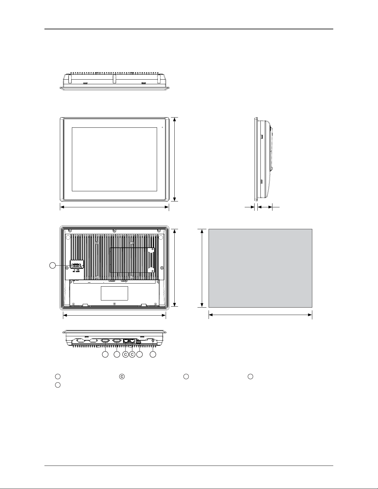
OMI6707A Dimensions
APower Connector Ethernet Port DUSB 2.0 Ports ELine out
BCom Port DE9P
Top View
Front View
Bottom View
Rear View
5.43
[138.0]
7.56
[192.0]
Side View
7.48
[190.0]
5.35
[136.0] 5.87
[149.0]
7.95”
[202.0]
IMPORTANT
Dimensions shown are
estimates, and may not work
with your mounting scheme. We
recommend measuring your
actualcutout dimensions for a
proper fit.
0.24
[6.0] 1.30
[33.0]
CutoutDimensions
A
BB D E
Dimensions are in inches [mm]

OMI Operations Manual: OMI6700 Series 7
OMI Operations Manual: OMI6700 Series 7
OMI6707A Specifications
System
CPU
Intel Atom Cedar View N2600 1.6 GHz Dual Core processor
System Chipset
Intel NM10
System Memory
Onboard DDR3 2 GB 800 MHz
I/O Ports
USB
USB 2.0 type A x 2
Serial
COM1: RS-232/422/485 DE-9P (default RS-232)
COM2: RS-232 DE-9P
Audio
1 x 3.5 mm line out
LAN
GbE RJ-45 x 2
Power
3 pins terminal block connector, DC power input
Storage
Solid State Drive
Base Model: 32 GB SSD, 1 x 1.8” SATA 2, MLC
Upgrade Option: 64 GB SSD, 1 x 1.8” SATA 2, MLC
Upgrade Option: 128 GB SSD, 1 x 1.8” SATA 2, MLC
Upgrade Option: 256 GB SSD, 1 x 1.8” SATA 2, MLC
SD Card Slot
1 x internal secure digital memory card socket, up to 32 GB
Expansion
Expansion Slot
N/A
Display
Display Type
7” TFT-LCD
Max. Resolution
800 x 480
Max. Color
262K
Luminance (cd/m²)
350
View Angle (H°/V°)
140/110
Contrast Ratio
400:1
Backlight Lifetime (hours)
40,000+
Touch Screen
Type
Resistive touch
Interface
RS-232
Light Transmission
80%
Electrical
Input Voltage
9~36 VDC
Input Current
0.4 ~ 1.5 A
Input Power
12.8 W
Mechanical
Construction
Silver aluminum front bezel and chassis
Rating
IP65 front panel / NEMA4X
Mounting
Panel mounting, VESA 75 x 75
Dimension (W x H x D)
7.95 x 5.87 x 1.54 inches [202 x 149 x 39 mm]
Net Weight
2.52 lbs [1.14 kg]
Environmental
Operating Temperature
32~122°F [0~50°C]
Storage Temperature
-4~140°F [-20~60°C]
Storage Humidity
10 to 90% @ 40°C, non-condensing
Certification
CE / FCC Class A / cULus / RoHS
Operating System
Type
Base Model: Microsoft Windows© Embedded Standard 7 32-bit (WS7P)
Upgrade Option: Microsoft Windows© 7 Pro for Embedded 32-bit (FES 7 Pro)
Notes
Specifications subject to change without notice.

OMI Operations Manual: OMI6700 Series 8
OMI Operations Manual: OMI6700 Series 8
OMI6710A Dimensions
APower Connector Ethernet Port DUSB 2.0 Ports ELine out
BCom Port DE9P
Top View
Front View
Bottom View
Rear View
6.93
[176.0]
10.71
[272.0]
Side View
10.63
[270.0]
6.85
[174.0] 7.44
[189.0]
11.22
[285.0]
IMPORTANT
Dimensions shown are
estimates, and may not work
with your mounting scheme. We
recommend measuring your
actualcutout dimensions for a
proper fit.
0.28
[7.0] 1.65
[41.9]
Cutout Dimensions
A
BB D E
Dimensions are in inches [mm]

OMI Operations Manual: OMI6700 Series 9
OMI Operations Manual: OMI6700 Series 9
OMI6710A Specifications
System
CPU
Intel Atom Cedar View N2600 1.6 GHz Dual Core processor
System Chipset
Intel NM10
System Memory
Onboard DDR3 2 GB 800 MHz
I/O Ports
USB
USB 2.0 type A x 2
Serial
COM1: RS-232/422/485 DE-9P (default RS-232)
COM2: RS-232 DE-9P
Audio
1 x 3.5mm line out
LAN
GbE RJ-45 x 2
Power
3 pins terminal block connector, DC power input
Storage
Solid State Drive
Base Model: 32 GB SSD, 1 x 2.5” SATA 2, MLC
Upgrade Option: 64 GB SSD, 1 x 1.8” SATA 2, MLC
Upgrade Option: 128 GB SSD, 1 x 1.8” SATA 2, MLC
Upgrade Option: 256 GB SSD, 1 x 1.8” SATA 2, MLC
SD Card Slot
1 x internal secure digital memory card socket, up to 32 GB
Expansion
Expansion Slot
N/A
Display
Display Type
10.1” TFT-LCD
Max. Resolution
1280 x 800
Max. Color
16.7M
Luminance (cd/m²)
350
View Angle (H°/V°)
160/160
Contrast Ratio
800:1
Backlight Lifetime (hours)
50,000+
Touch Screen
Type
Resistive touch
Interface
RS-232
Light Transmission
80%
Electrical
Input Voltage
9~36 VDC
Input Current
0.6 ~ 2.1 A
Input Power
21.8 W
Mechanical
Construction
Silver aluminum front bezel and chassis
Rating
IP65 front panel / NEMA4x
Mounting
Panel mounting, VESA 100 x 100
Dimension (W x H x D)
11.22 x 7.44 x 1.93 inches [285 x 189 x 48.9 mm]
Net Weight
4.1 lbs [1.9 kg]
Environmental
Operating Temperature
32~122°F [0~50°C]
Storage Temperature
-4~140°F [-20~60°C]
Storage Humidity
10 to 90% @ 40°C, non-condensing
Certification
CE / FCC Class A / cULus / RoHS
Operating System
Type
Base Model: Microsoft Windows© Embedded Standard 7 32-bit (WS7P)
Upgrade Option: Microsoft Windows© 7 Pro for Embedded 32-bit (FES 7 Pro)
Notes
Specifications subject to change without notice.
OMI Operations Manual: OMI6700 Series 10
OMI Operations Manual: OMI6700 Series 10
OMI6712A Dimensions
APower Connector Ethernet Port DUSB 2.0 Ports ELine out
BCom Port DE9P
Top View
Front View
Bottom View
Rear View
9.02
[229.0]
11.93
[303.0]
Side View
11.85
[301.0]
8.94
[227.0] 9.65
[245.0]
12.56
[319.0]
IMPORTANT
Dimensions shown are
estimates, and may not work
with your mounting scheme. We
recommend measuring your
actual cutout dimensions for a
proper fit.
0.33
[8.4] 1.70
[43.3]
Cutout Dimensions
Line- Out
BB D E
LAN 2 C O M 1 C O M2LAN 1U SB
A
Dimensions are in inches [mm]

OMI Operations Manual: OMI6700 Series 11
OMI Operations Manual: OMI6700 Series 11
OMI6712A Specifications
System
CPU
Intel Atom Cedar View N2600 1.6 GHz Dual Core processor
System Chipset
Intel NM10
System Memory
Onboard DDR3 2 GB 800 MHz
I/O Ports
USB
USB 2.0 type A x 2
Serial
COM1: RS-232/422/485 DE-9P (default RS-232)
COM2: RS-232 DE-9P
Audio
1 x 3.5 mm line out
LAN
GbE RJ-45 x 2
Power
3 pins terminal block connector, DC power input
Storage Space
Solid State Drive
Base Model: 32 GB SSD, 1 x 2.5” SATA 2, MLC
Upgrade Option: 64 GB SSD, 1 x 1.8” SATA 2, MLC
Upgrade Option: 128 GB SSD, 1 x 1.8” SATA 2, MLC
Upgrade Option: 256 GB SSD, 1 x 1.8” SATA 2, MLC
SD Card Slot
1 x internal secure digital memory card socket, up to 32 GB
Expansion
Expansion Slot
N/A
Display
Display Type
12.1” TFT-LCD
Max. Resolution
800 x 600
Max. Color
16.2M
Luminance (cd/m²)
330
View Angle (H°/V°)
160/140
Contrast Ratio
800:1
Backlight Lifetime (hours)
50,000+
Touch Screen
Type
Resistive touch
Interface
RS-232
Light Transmission
80%
Electrical
Input Voltage
9~36 VDC
Input Current
0.5 ~ 2 A
Input Power
19.2 W
Mechanical
Construction
Silver aluminum front bezel and chassis
Rating
IP65 front panel / NEMA4X
Mounting
Panel mounting, VESA 100 x 100
Dimension
12.56 x 9.65 x 2.03 inches [319 x 245 x 51.7 mm]
Net Weight
5.7 lbs [2.6 kg]
Environmental
Operating Temperature
32~122°F [0~50°C]
Storage Temperature
-4~140°F [-20~60°C]
Storage Humidity
10 to 90% @ 40°C, non-condensing
Certification
CE / FCC Class A / cULus / RoHS
Operating System
Type
Base Model: Microsoft Windows© Embedded Standard 7 32-bit (WS7P)
Upgrade Option: Microsoft Windows© 7 Pro for Embedded 32-bit (FES 7 Pro)
Notes
Specifications subject to change without notice.

OMI Operations Manual: OMI6700 Series 12
OMI Operations Manual: OMI6700 Series 12
OMI6715A Dimensions
APower Connector Ethernet Ports DUSB 2.0 Ports ELine out
BCom Port DE9P
Top View
Front View
Bottom View
Rear View
11.50
[292.0]
15.43
[392.0]
Side View
15.36
[390.0]
11.42
[290.0] 12.20
[310.0]
16.14
[410.0]
IMPORTANT
Dimensions shown are
estimates, and may not work
with your mounting scheme. We
recommend measuring your
actual cutout dimensionsfor a
proper fit.
0.33
[8.4] 1.82
[46.3]
CutoutDimensions
LAN 2 C O M 1 C O M2
LAN 1
U SB
Line- Ou t
B D EB
A
Dimensions are in inches [mm]

OMI Operations Manual: OMI6700 Series 13
OMI Operations Manual: OMI6700 Series 13
OMI6715A Specifications
System
CPU
Intel Atom Cedar View N2600 1.6 GHz Dual Core processor
System Chipset
Intel NM10
System Memory
Onboard DDR3 2 GB 800 MHz
I/O Ports
USB
USB 2.0 type A x 2
Serial
COM1: RS-232/422/485 DE-9P (default RS-232)
COM2: RS-232 DE-9P
Audio
1 x 3.5mm line out
LAN
GbE RJ-45 x 2
Power
3 pins terminal block connector, DC power input
Storage
Solid State Drive
Base Model: 32 GB SSD, 1 x 2.5” SATA 2, MLC
Upgrade Option: 64 GB SSD, 1 x 1.8” SATA 2, MLC
Upgrade Option: 128 GB SSD, 1 x 1.8” SATA 2, MLC
Upgrade Option: 256 GB SSD, 1 x 1.8” SATA 2, MLC
SD Card Slot
1 x internal secure digital memory card socket, up to 32 GB
Expansion
Expansion Slot
N/A
Display
Display Type
15" TFT-LCD
Max. Resolution
1024 x 768
Max. Color
16.2M
Luminance (cd/m²)
350
View Angle (H°/V°)
160/145
Contrast Ratio
800:1
Backlight Lifetime (hours)
50,000+
Touch Screen
Type
Resistive touch
Interface
RS-232
Light Transmission
80%
Electrical
Input Voltage
9~36 VDC
Input Current
0.7 ~ 2.6 A
Input Power
25.6 W
Mechanical
Construction
Silver aluminum front bezel and chassis
Rating
IP65 front panel / NEMA4X
Mounting
Panel mounting, VESA 100 x 100
Dimension (W x H x D)
16.14 x 12.20 x 2.15 inches [410 x 310 x 54.67mm]
Net Weight
9.7 lbs [4.4kg]
Environmental
Operating Temperature
32~122°F [0~50°C]
Storage Temperature
-4~140°F [-20~60°C]
Storage Humidity
10 to 90% @ 40°C, non-condensing
Certification
CE / FCC Class A / cULus / RoHS
Operating System
Type
Base Model: Microsoft Windows© Embedded Standard 7 32-bit (WS7P)
Upgrade Option: Microsoft Windows© 7 Pro for Embedded 32-bit (FES 7 Pro)
Notes
Specifications subject to change without notice.
OMI Operations Manual: OMI6700 Series 14
OMI Operations Manual: OMI6700 Series 14
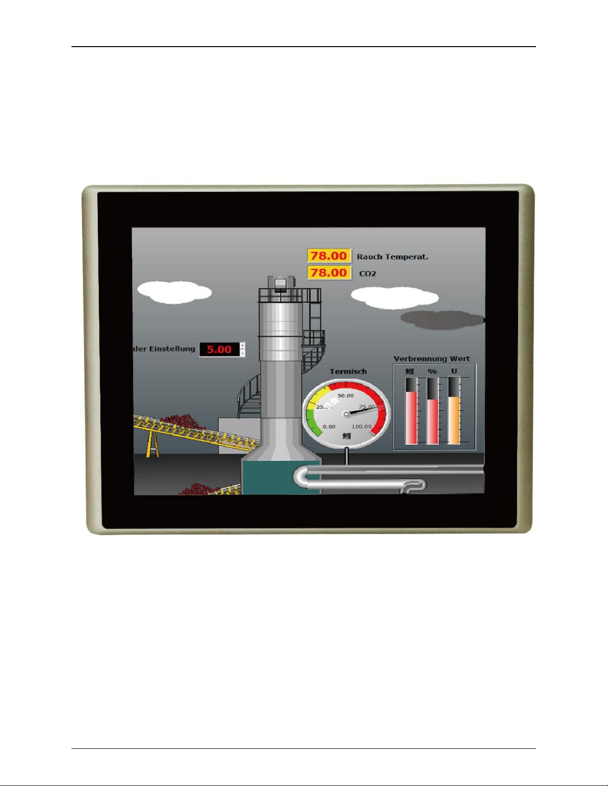
OVERVIEW OF OMI6700 SERIES
The OMI6700 Series is available in 7”, 10.1”, 12.1”, and 15” screen sizes. The OMI6700 is fanless
and compact with a flat panel touch screen, and is powered by the Intel Atom N2600 1.6 GHz
dual-core processor with built-in 2GB DDR3 800MHz.
Front View of OMI6700 SERIES

OMI Operations Manual: OMI6700 Series 15
OMI Operations Manual: OMI6700 Series 15
Rear View of OMI6707
Rear View of OMI6710

OMI Operations Manual: OMI6700 Series 16
OMI Operations Manual: OMI6700 Series 16
Rear View of OMI6712
Rear View of OMI6715

OMI Operations Manual: OMI6700 Series 17
OMI Operations Manual: OMI6700 Series 17
I/O PORTS
COM1 and COM2:
Connector Type: DE9P male serial ports.
COM1*
COM2
Pin #
(RS-232 Default)
(RS422)
(RS485)
(RS232)
1
DCD
422_RX+
NC
DCD
2
RXD
422_RX-
NC
RXD
3
TXD
422_TX-
485-
TXD
4
DTR
422_TX+
485+
DTR
5
GND
GND
GND
GND
6
DSR
NC
NC
DSR
7
RTS
NC
NC
RTS
8
CTS
NC
NC
CTS
9
RI
NC
NC
RI
* Refer to “Setting COM1 Function” to set the communication mode.
Line Out:
Connector Type: 3.5mm audio jack.
Line out HD Audio port can be connected to a headphone or amplifier.

OMI Operations Manual: OMI6700 Series 18
OMI Operations Manual: OMI6700 Series 18
USB:
OMI6700 models have 2 ea USB 2.0 type A port.
Note: USB 2.0 allows data transfers up to 480 Mb/s, full-speed, and low-speed signaling.
The current limit is 1.5A
LAN1 and LAN2:
Standard 10/100/1000M RJ-45 Ethernet ports, LINK LED (green) and ACTIVE LED
(yellow) respectively located at the left-hand and right-hand side of the Ethernet port
indicate the activity and transmission state of the network.
OMI Operations Manual: OMI6700 Series 19
OMI Operations Manual: OMI6700 Series 19
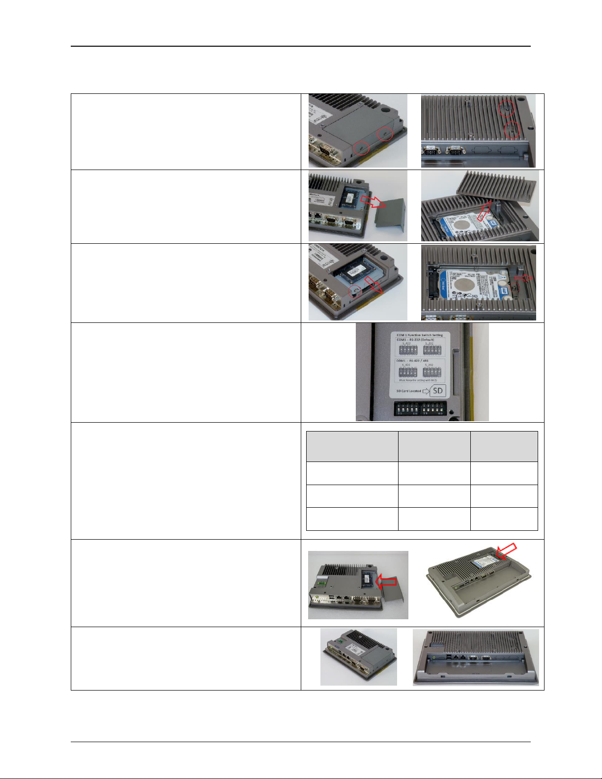
SETTING COM1 FUNCTION
1. Using a #1 Phillips screwdriver, remove
the 2 Phillips screws indicated in the
figure.
or
2. Remove the storage cover by lifting it out
of the unit.
or
3. Using a #1 Phillips screwdriver, remove
the 1 screw retaining the storage bracket.
Then carefully slide the bracket out of the
unit.
or
4. The DIP switches are now visible.
5. Reference the “COM1 Function Switch
Setting” label and/or the following chart to
set the DIP switches to the desired RS-
232, RS-422, or RS-485 communication
mode.
Function
S_422
(all switches)
S_232
(all switches)
RS232 (Default)
OFF
ON
RS422
ON
OFF
RS485
ON
OFF
6. Slide the bracket and storage device into
the OMI, securing it with the screw
removed in step 3.
or
7. Replace the storage cover and secure it
with the screws removed in step 1.
or
OMI Operations Manual: OMI6700 Series 20
OMI Operations Manual: OMI6700 Series 20
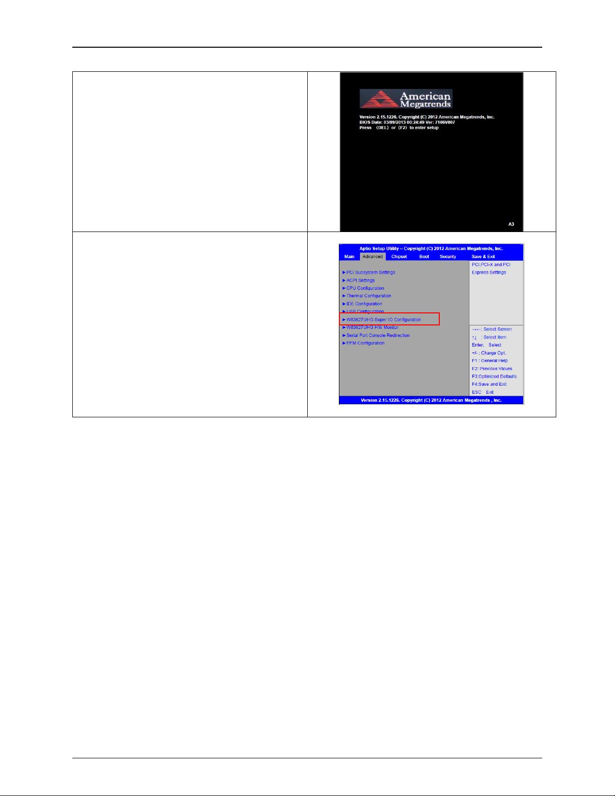
8. Enter the BIOS Setup Utility to select the
desired communication mode by pressing
[Delete] key during POST. The Main
menu containing the system summary
information will appear.
9. Set the “UART Mode Selection” to the
desired COM1 communication mode as
follows:
Advanced
W83627UHG Super IO Configuration
Serial Port 1 Configuration
UART Mode Selection:
[RS-232]
[RS-485]
[RS-422]
This manual suits for next models
4
Table of contents
Other Maple Systems Industrial PC manuals


