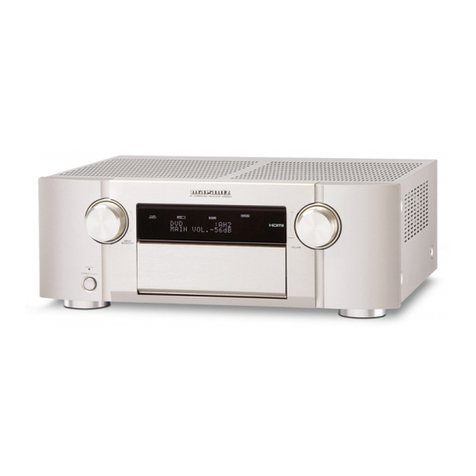
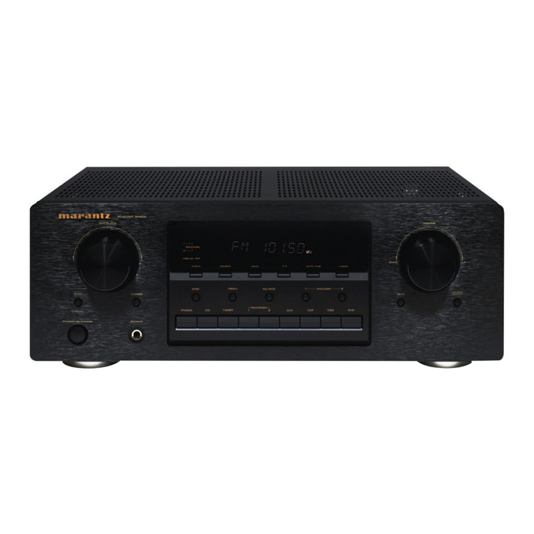
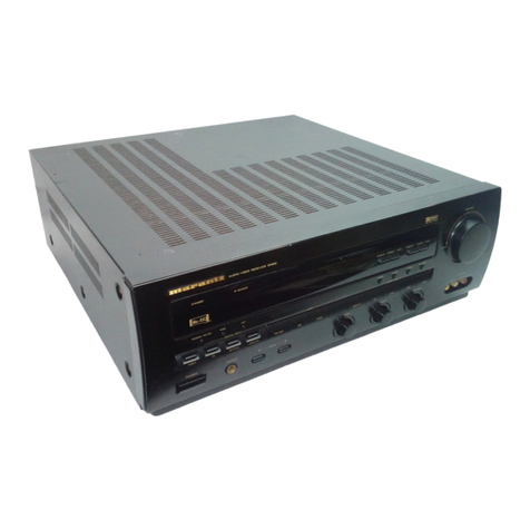
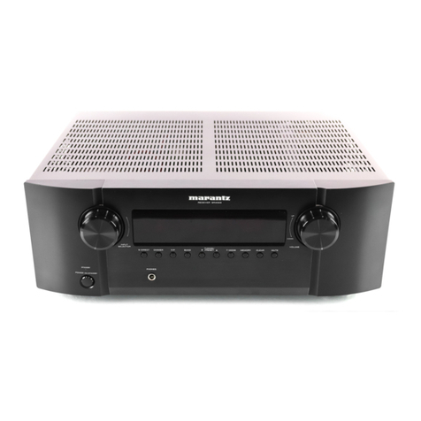
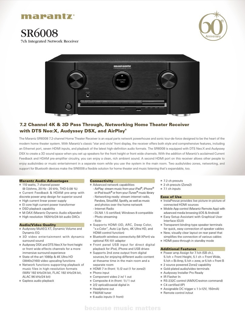
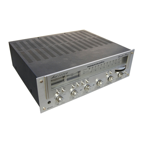
Marantz 2270 User manual

+
:
ERR
a®
Hoan
en
EZ
model
2270

f
i
TABLE
OF
CONTENTS
INtrOdUCTION
isi
ee
es
ck
ee
eee
ee
eae
ee
ee
eohises
Puan
aren
eayb
dnd
Seales's
GleiA
averacaeoad
‘
Service
Notes
...........
Peg
ase ety
Sisre
we
Gleb
dhacwry.e
Cee
Gand
wteere
S
elkcee
dale,
eee
waits
AME
TUN
GP:
25
oe
cee
eee
ies
OS
Gk
Sw
ee
eee
eek
wee
aparece
dt
Bes
Meee
ease
bod
Mk
eed
ee
EM
TUN
GR
e526
econ
b
ices
etnies
eke
auere
ee
Lib
ayawanats
edible
atave
srt
velvatte
fete
8
ret
whe
Phono
and
Tone
Amplifiers
............
00:
c
cece
eee
ene
eens
nr
ee
:
Power
Amplifier
...........
Sse
SU
woetedbta
ae
Sete
ead
raveee
dara
Sie
Sisiy
anes
ath
eae
oo
eee
hs
Power
Protection
Circuit..........
SUMS
Baie
ee
Ra
BAe
ere
et
ee
OM
ES
a
aoe
ad
a
RE
Sih
ies
Speaker
Protection
Relay
Circuit
....................
Se
eC
ee
Se
rae
Suggestion
for
Trouble
Shooting
of
Power
Amplifier
........
aes
varhan'e
ratte.
Sieh
ee
ie
we
ate
oe
Voltage
Conversion...
1.2.2...
0.0.
c
cece
ete
ee
eee
Pe
gests
fe
and
4
ori
Saas
Sew
alata
orate
Test
Equipment
Required
for
Servicing
.................
Hide
e
Gee
wae
Sao
Shain
hon
ine
Bye
AM
Alignment
Procedure
...........
wate
Roe
ates
eheg
SS
Genet
aa
be
Sa
eaten
Be
nual
Shenae
a
FM
Alignment
Procedure
........
0.0.
cece
eee
ect
eee
ee
eee
ee
teeta
tree
nea
Stereo
Separation
Alignment
.......
Sad
Sedan
We
Ciey
areata
Solar
aia
at
ous
gs
hasta
eG
sitar
Scatiotane
Wh
Muting:
Circuit:
AL
GnMent
es
isi:
bcc
62
c8
eie
eS
ew
eles
e
per
ele
8
ia
ea
a
oie
ee
wD
ee
we
wees
Audio
Adjustment
.............
Seles
Grae
ee
we
ee
Gee
eer
ean
bared
Kays
Aaa
ads
Oe
Parts
List.............
Awe
gaara
hoe
Raa
etsaN
he:
Bedale
Soedavarte
tes
ee
Evahe
ark
evades,
Grararenetey
Specifications
i
iciw
iia
eis
Bau
seers
bea
hs
ea
ae
Geen
Bee
Gee
OA
ee
OOH
WKOKDOGO
PAN
aA
aa
WN
z=
WWOO
LIST
OF
ILLUSTRATIONS
”
FIGURE
NO
PAGE
(
1.
Remove
the
Terminal
Cover
.........
0.
cece
cece
eee
etter
e
eee
ecceee
§
2.
Voltage
Conversion
Chart
........
0.
ee
cee
ee
eee
eet
e
eee
teen
cceee
7
3.
Lissajou
Figure
on
Oscilloscope
.......
0...
cee
eee
eee
tee
teeta
eee
TM
4.
Dial
Stringing.
......
2...
cee
eee
apanar
stnjaete
aL
grayerannperesetee
susdcacaeatine
niet
TE
5.
Front
Panel
Adjustment
and
Component
Locations
........
bay
dvetetridand
feet
ices
Per
(74
6.
Main
Chassis
Component
Locations
(Top
View)
............002ececeeeeeeees
..
12
7.
Rear
Panel
Adjustment
and
Component
Locations
.....
sib
aa
8
WictECages
wiikede
es
Cate
cas
me
NS
8.
Main
Chassis
Component
Locations
(Bottom
View)
........
bagel
teed
er
aren
..
13
9.
FM
Front
End
Assembly
P100
Component
Locations..............02.
000
eee
eee
14
10.
FM
1F
Amplifier
Assembly
P200
Component
Locations
...............
00200000)
14
11.
FM
Detector
Assembly
P500
Component
Locations
.
gpethotabteale,
ek
Siwadl
(o0e
Seer
aatnaateleud
15
12.
MPX
Stereo
Decoding
Amplifier
Assembly
P300
Companeht
Leearions
ee
ee
eee
ia
1D
13.
Muting
Control
Amplifier
Assembly
P550
Component
Locations
................
.
16
14.
AM
Tuner
Unit
Assembly
P150
Component
Locations
..........
Maan
Meee
Pees
16
15.
Phono
Amplifier
Assembly
P700
Component
Locations
...............
2200000
e
17
A
16.
Tone
Amplifier
Assembly
P400
Component
Locations
............
0.0.0
eee
eee
17
17.
Tone
Control
Unit
Assembly
P450
Component
Locations
.............
Bie
ene
Sans
18
18.
Power
Amplifier
Assembly
P750
Component
Locations
............
......+5.
eae
19
‘
-19.
Regulated
Power
Supply
and
Protection
Relay
Circuit
Assembly
P800
Component
Locations
..................--
aed
Duaia
ats.
eared
Hae
RS
ee
a
eee
20
20.
Mono,
High
and
Low
Filter
Switch
Unit
Assembly’
P600
Component
Locations......
21
21.
Loudness,
Muting
and
Speakers
Switch
Assembly
P650
Component
Locations.......
21
22.
Schematic
Diagram
................--
jostee
MERE
Ale
tare
tl
A
Bare
MN
eh
eats
22

INTRODUCTION
This
service
manual
was
prepared
for
use
by
Authorized
Warranty
Stations
and
contains
service
information
for
Marantz
Model
2270
Stereophonic
Receiver.
Servicing
information
and
voltage
data
included
in
this
manual
are
intended
for
use
by
the
knowledgeable
and
experienced
technician
only.
All
instruction
should
be
read
carefully.
No
attempt
should
be
made
to
proceed
without
a
good
understanding
of
the
operation
in
the
receiver.
The
parts
list
furnish
information
by
which
replacement
part
may
be
ordered
from
the
Marantz
Company.
A
simple
description
is
included
for
parts
which
can
be
usually
be
obtained
through
local
suppliers.
1.
Service
Notes
As
can
be
seen
from
the
circuit
diagram
the
chassis
of
Model
2270
consists
of
the
following
units.
Each
unit
mounted
on
a
printed
circuit
board
is
described
within
the
square
enclosed
by
a
bold
dotted
line
on
the
circuit
diagram.
1.
FM
Front
End...
02...
ec
ee
ee
eee
eee
mounted
on
P.C.
Board
P100
2.
FM
IF
Amplifier...
0.0.0...
cc
eee
ce
eee
eee
eee
mounted
on
P.C.
Board
P200
Si
FM
Detector
on
aie
ne
Beh
ee
Sb
ee
ee
eae
SE
eA
mounted
on
P.C.
Board
P500
4.
MPX
Stereo
Decoding
Amplifier............
00.0.0
eee aee
mounted
on
P.C.
Board
P300
5.
Muting
Control
Amplifier.
........
0.0.0...
0
eee
eee
eee
mounted
on
P.C.
Board
P550
G2
AM
Tuner
Uaits
«cas
seein
G
een
Gea
Geers
wee
eas
mounted
on
P.C.
Board
P150
7.
Phono:
Amplifier...
occas
be ee
ei
eee
eee
eee
ee es
mounted
on
P.C.
Board
P700
8.
Tone
Amplifier...
2.0.0...
cece
ee ee
eee
mounted
on
P.C.
Board
P400
9.
Tone
Control
Unit
2.0...
...
ce
ee
eee
mounted
on
P.C.
Board
P450
10.
Power
Amplifier
.....0.
0.0...
ccc
cee
eee
ee
eee
eee
mounted
on
P.C.
Board
P750
11.
Regulated
Power
Supply
and
Protection
Relay
Circuit.......
mounted
on
P.C.
Board
P800
12.
Mono,
High
and
Low
Filter
Switch
unit
..................
mounted
on
P.C.
Board
P600
13.
Loudness,
Muting
and
Speakers
Switch
unit
..............
mounted
on
P.C.
Board
P650
2.
AM
Tuner
All
components
except
Tuning
capacitor
and
ferrite
bar
antenna
are
mounted
on
a
printed
circuit
board
P
150.
The
AM
signals
induced
in
a
ferrite
bar
antenna
are
applied
to
the
base
of
RF
amplifier
transistor
H151
through
a
capacitor
of
C151
and
amplified
to
the
level
required
for
overcoming
the
conversion
noises,
thus
giving
good
S/N
performance.
The
tuned
circuits
inserted
in
both
Out-and
in-put
circuit
of
the
RF
amplifier
assure
very
high
image
and
spurious
rejection
performance.
Thus
amplified
and
selected
AM
signals
are
then
applied
to
the
base
of
converter
transistor
H152
through
a
coupling
capacitor
C156.
While
the
local
oscillator
voltage
is
injected
to
the
emitter
of
H152
through
a
capacitor
C157.
Both
AM
signals
and
oscillating
voltage
are
mixed
at
the
base-emitter
junction
and
converted
into
455KHz
intermediate
frequency.
The
resulting
IF
signal
is
applied
to
the
first
IF
transformer
L153
consisting
of
one
ceramic
filter
and
two
tuned
circuits.
The
output
of
L153
is
led
to
the
transistor
H153
which
in
turn
apply
its
output
to
the
transistor
of
next
stage
H154.
The
fully
amplified
IF
output
is
then
applied
to
the
diode
H157
to
detect
audible
signal
through
the
detector
transformer
L154.
The
detected
audio
signal
is
filtered
and
amplified
and
the
final
audio
output
is
obtained
from
the
collector
of
H155
and
applied:
one
to
the
tape
out
jacks
through
monitor
switch
on
the
front
panel
and
the
other
to-the
function
rotary
switch.
The
DC
component
of
the
detected
IF
signal
is
used
as
a
AGC
voltage
to
control
emitter
current
of
H153
which
in
turn
control
the
bias
current
of
the
RF
amplifier
through
the
resistor
R179
and
R151.
A
part
of
IF
signal
output
is
also
applied
to
the
diode
H158
through
a
capacitor
C167
and
rectified
to
obtain
DC
current
for
energizing
the
AM
signal
strength
meter
M0071.

2.2
Suggestions
for
AM
Tuner
trouble
shooting
Check
for
broken
AM
bar
antenna,
next
try
to
tune
station
by
rotating
fly-wheel
tuning
knob
slowly
and
observe
the
AM
signal
strength
meter
whether
it
deflects
or
not.
if
the
signal
strength
meter
gives
a
deflection
at
several
frequencies
received,
no
failure
may
exist
in
the
stages
at
least
preceding
final
IF
transformer
L154.
Next
connect
a
oscilloscope
to
the
pin
terminal
J162
or
J157
and
check
for
audio
signals
with
the
tuning
meter
deflected.
If
the
signal
strength
meter
does
not
deflect,
check
the
loca!
oscillator
circuit.
Normal
oscillating
voltage
at
the
hot
end
of
the
oscillator
tuning
capacitor
is
about
2
or
3
volts,
varying
with
tuning
capacitor
position.
When
measuring
oscillating
voltage
use
a
RF
VTVM,
no
circuit
tester
gives
correct
indication.
If
the
local
oscillator
voltage
is
normal,
check
all
voltage
distribution
in
the
AM
circuits
by
using
a
DC
VTVM
and
compare
the
measured
values
with
those
given
in
the
schematic
diagram.
3.
FM
TUNER
The
FM
Tuner
section
of
Model
2270
is
divided
into
five
functional
blocks:
FM
Front
End,
IF
Amplifier,
Detector,
Muting
Control
and
MPX
Stereo
Decoding
Circuit.
FM
signals
induced
by
a
FM
antenna
are
led
to
FM
antenna
coil
L101
through
an
attenuator
switch
and
a
balun
coil.
These
signals
are
then
applied
to
the
FET
RF
amplifier
which
in
turn
applies
its
output
to
the
next
FET
Mixer
H102
through
the
triple
tuned
high
selective
circuits.
The
FET
Mixer
convert
its
input
signal
into
10.7MHz
intermediate
frequency
and
amplifies
it
at
the
same
time.
The
H103
is
a
local
oscillator
and
its
output
is
injected
into
the
source
of
the
FET
Mixer,
the
injection
voltage
is
about
700mV.
The
10.7MHz
front
end
output
is
led
to
the
next
IF
amplifier
unit
through
a
coaxial
cable.
The
IF
amplifier
unit
consists
of
six
stages
of
IF
amplifier,
one
stage
of
AGC
amplifier
and
two
stages
of
multipath
signal
amplifiers.
Eight
pieces
of
ceramic
filters
are
also
used
to
obtain
high
selectivity
three
stages
of
symmetrical
diode
limiters
are
also
employed
for
the
best
limitting
characteristics,
improved
capture
ratio
and
good
AM
suppression.
A
part
of
FM
Front
End
output
is
applied
to
the
AGC
amplifier
H207
and
rectified
its
output
is
fed
back
to
the
gate
of
FET
RF
amplifier
to
decrease
the
gain
with
increased
signal
strength.
The
signals
required
for
multipath
indication
are
obtained
from
the
three
stages
of
IF
amplifiers
through
coupling
capacitors
C234,
C236
and
C238
respectively
and
rectified
by
three
pair
of
full
wave
diode
circuits.
Thus
obtained
AM
components
of
the
FM
signal
is
amplified
by
the
transistor
H208
and
H209
and
its
output
is
again
rectified
to
obtain
DC
current
required
for
actuating
the
Multipath
indication
meter.
The
IF
signal
sufficiently
amplified
through
every
stage
of
IF
amplifier
is
finally
applied
to
the
IC
limiter
on
the
Detector
Unit.
The
detected
audio
output
is
led
to
the
buffer
amplifier
H502
and
its
buffered
output
is
led
to;
(a)
noise
amplifier
H551
through
resistor
R551
and
capacitor
C551,
(b)
Quad
Radial
Jacks
on
the
rear
panel
through
resistor
R564,
(c)
MPX
stereo
decoding
circuit
through
R563.
The
DC
current
caused
at
the
third
windings
of
the
discriminator
transformer
is
directly
applied
to
the
FM
center
tuning
meter.
Audio
Muting
and
Stereo
mode
auto-selecting
circuit
The
muting
circuit
consisting
of
all
solid-state
electrical
switching
has
been
incorporated
in
the
Model
2270.
Three
inputs
control
the
muting
function.
The
first
is
related
to
signal
strength,
the
second
to
the
noise
condition
at
the
detector
and
the
third
is
derived
from
the
DC
component
of
the
detector
output.
These
inputs
are
properly
matrixed
and
gated
to
provide
muting
free
from
noise
and
transients.
The
first
input
of
DC
voltage
obtained
by
rectifing
a
part
of
IF
output
signal
from
the
H206
is
applied
to
the
base
of
H306
and
turns
on
it,
if
the
IF
output
is
greater
than
predetermined
level
(muting
threshold
level).
When
the
H306
is
turned
on
the
H307
is
turned
off,
allowing
the
emitter-collector
resistance
increasing
and
the
collector
voltage
rises
about
9.7V.
The
increased

collector
voltage
increases
the
gate
bias
voltage
and
turns
on
the
switching
FET
H308,
decreasing
the
source-drain
resistance
to
near
zero
ohm
and
allowing
the
audio
signal
applied
to
the
source
to
flow
to
the
center
of
38KHz
switching
transformer
through
the
source-drain
path.
When
the
input
signal
is
lower
than
predetermined
level,
the
DC
output
obtained
is
small
and
can
not
turn
on
the
H306,
thus
the
H306
keeps
its
turn-off
state
and
this
makes
H307
turn
on,
decreasing
the
collector
voltage
and
turning
off
H308.
Thus
no
audio
signals
can
pass
through
the
FET.
This
is
the
fundamental
principle
of
the
muting
operation
but
for
more
elaborate
muting
operation
the
second
and
the
third
inputs
are
necessary.
The
second
input
is
used
to
protect
the
muting
operation
and
MPX
stereo
beacon
lamps
from
misoperation
due
to
undesirable
noises.
The
high
frequency
noises
included
in
the
detected
audio
signals
are
separated
by
a
small
capacitor
C551
and
amplified
by
the
noise
amplifier
transistor
H551
and
its
output
is
rectified
by
the
two
diodes.
The
rectified
DC
output
is
proportional
to
the
noise
components
in
the
audio
signals.
When
there
are
excessive
noises
in
the
audio
signals
such
as
obtained
with
a
station
incorrectly
tuned
in,
the
rectified
DC
output
turns
on
the
transistor
H522,
decreasing
the
emitter-collector
resistance
to
zero.
This
means
the
collector
of
H307
is
short-circuited
to
the
ground,
therefore
the
H308
is
turned
off
and
any
audio
signals
having
excessive
high
frequency
noises
can
not
go
through
the
FET’s
sourcedrain
path.
The
transistor
H303
connected
in
series
with
the
19KHz
pilot
signal
amplifier
transistor
H302
is
also
turned
off
(when
the
transistor
H522
or
H307
are
turned
on.)
and
no
current
flows
in
the
H302,
resulting
in
turning
off
the
streo
beacon
lamps.
Thus
misoperation
due
to
undesirable
noises
is
also
avoided.
The
third
input
is
obtained
from
the
FM
discriminator
circuit.
The
DC
output
so
called
‘’S’’
curve
is
applied
to
the
gate
of
H558
through
a
resistor
R523
and
deviding
network
(R565
&
R566).
The
DC
output
is
zero
with
a
station
correctly
tuned
in,
but
will
vary
from
negative
to
positive
values
or
vice
versa
when
the
tuning
point
is
deviated
toward
either
plus
or
minus
frequency
from
the
correct
tuning
frequency.
When
the
DC
output
is
increased
to
a
greater
level
than
that
of
predetermined,
the
increased
source
potential
of
H558
makes
the
transistor
H561
turn
on,
and
this
makes
the
H306
turn
off,....H307
turn
on,
....
H308
turn
off,
....
H303
turn
off
(this
means
no
19KHz
pilot
signal
is
amplified
and
no
stereo
beacon
is
turned
on.)
When
the
DC
output
is
increased
to
the
negative
predetermined
level,
the
decreased
source
potential
turns
off
the
H559
which
in
turn
makes
the
H560
turn
on
and
the
H306
is
turned
off.
The
subsequent
changes
are
exactly
the
same
as
that
just
described
above.
;
Thus
when
the
tuning
is
shifted
or
deviated
to
the
certain
frequencies
in
which
undesirable
noisy
side-audio
signals
are
produced,
both
muting
and
19KHz
switching
transistors
are
operated
automatically
and
open
the
circuits.
With
the
station
correctly
tuned
in,
the
bias
current
of
the
FET
H558
is
adjusted
so
that
both
transistor
H560
and
H5671
are
not
turned
on,
giving
no
effect
on
the transistor
H306.
MPX
Stereo
Decoding
Circuit
The
buffered
and
non-equalized
audio
signals
are
applied
to
the
first
amplifier
H301
which
serve
as
a
tuned
amplifier
for
the
pilot
signal
in
the
composite
signals
and
as
a
buffer
amplifier
for
the
audio
signals.
The
amplified
19KHz
pilot
signal
is
led
to
the
second
19KHz
amplifier
H302
and
further
amplified
if
switching
transistor
H303
in
turned
on
by
the
controlling
DC
signal
as
described
in
the
preceding
chapter.
The
final
19KHz
pilot
signal
is
rectified
by
the
doubler
circuit
consisting
of
the
H315
and
H316
to
obtain
synchronized
38KHz
amplifier
driving
signal.
The
H304
is
the
38KHz
tuned
amplifier
and
supplies
its
output
to
the
switching
matrix
circuit
consisting
of
four
diodes.
While
the
composite
signals
are
applied
to
the
center
tap
of
switching
transformer
1/2
L302.
The
right
and
left
stereo
signals
decoded
by
the
switching
circuit
are
led
to
the
crosstalk
cancelling
amplifier
which
utilizes
complementary
configuration
with
NPN
and
PNP

transistors
through
de-emphasis
network
consisting
of
C315
and
R335,
and
C316
and
R336.
L305
is
a
low-pass
filter
networks
having
very
sharp
cut
off
characteristics
and
eliminates
undesirable
residual
switching
signals.
Transistors
H313
and
H314
are
buffer
amplifiers
and
their
outputs
are
led
to
the
function
switch.
3.2
Suggestion
for
Trouble
Shooting
of
FM
Tuner
3.2.1
Symptom:
No
FM
Reception
First
turn
on
the
power
switch
and
try
to
tune
FM
stations.
Rotate
the
fly-wheel
tuning
knob
slowly
and
observe
the
FM
signal
strength
meter
and
FM
center
tuning
meter.
If
the
center
tuning
meter
deflect
at
several
frequencies
received,
the
tuner
circuits
preceding
the
discriminator
circuit
may
have
no
failure.
If
the
signal
strength
meter
deflect
but
no
deflection
is
obtained
on
the
center
meter,
there
may
be
some
defects
around
the
detecting
circuit
consisting
H501,
L501,
H503,
H504,
etc.
When
no
reading
is
obtained
in
both
meters,
check
FM
local
oscillator
circuit,
using
a
RF
VTVM.
The
normal
local
oscillator
voltage
is
one
or
two
volts
(rms)
at
the
tuning
capacitor,
depending
on
the
tuning
capacitor
position.
If
the
local
oscillator
voltage
is
normal,
next
check
all
voltage
distribution
in
the
FM
Front
End
and
IF
amplifier
unit
and
compare
them
with
those
shown
in
the
circuit
diagram.
When
both
meters
deflect
but
no
sound
is
obtained,
check audio
circuits,
using
high
sensitive
oscilloscope.
3.2.2
Symptom:
No
Stereo
Separation
First
check
the
‘‘“MONO”’
switches
are
in
normal
out
position.
Connect
a
FM
RF
signal
generator
output
modulated
by
a
stereo
modulator
to
the
rear
FM
antenna
terminals,
and
check
the
stereo
beacon
is
turned
on
or
not.
If
not
turned
on,
check
for
19KHz
pilot
signal
and
38KHz
switching
signal,
using
an
oscilloscope.
4.
Phono
and
Tone
Amplifiers
Program
source
signals
from
the
PHONO
jacks
on the
rear
panel
are
supplied
to
the
input
circuit
of
the
Phono
Amplifier
through
the
selector
switch
and
the
output
of
the
Phono
Amplifier
is
applied
to
another
section
of
the
selector
switch.
This
amplifier
provides
a
gain
of
40dB.
All
signals
selected
by
the
function
switch
(SO02-3F,
4F)
are
led
to
the
balance
and
volume
controls
through
the
MONO(L,R)
and
Hi-Blend
switches.
Signals
properly
attenuated
by
the
volume
control
are
applied
to
the
tone
amplifier
and
subjected
to
the
tone
control
networks
such
as
bass,
mid,
treble
contro!
and
high
and
low
cut
filters.
.
Thus
controlled
audio
signals
are
then
led
to
the
PRE
OUT
jacks
on
the
rear
panel.
5.
Power
Amplifier
The
signal
from
the
tone
amplifier
is
applied
to
the
differential
amplifier
(base
of
H751)
through
the
coupling
capacitor
C751.
The
differential
amplifier
provides
very
high
input
impedance
and
its
collector
output
(H752)
is
applied
to
the
base
of
H753
which
in
turn
applies
its
Output
to
the
next
stage;
to
the
H756
through
the
network
R766,
C762
and
R771,
and
to
the
H757
through
the
network
R776,
C763
and
R772.
The
outputs
of
H756
and
H757
are
applied
to
the
H758
and
H757
respectively.
HOO1
and
HOO2
are
power
transistors
used
in
complementary
symmetry
configulation
and
mounted
on
the
heat
sink.
To
maintain
overall
amplifier
stability
and
linearity,
degenerative
feed
back
is
utilized
throughout
the
amplifier.
This
feed
back
is
also
necessary
to
reduce
distortion
to
within
specified
limit.
The
RC
network
R775
and
C756
condition
the
feed
back
signal
for
the
audio
signals.
R759
and
C755
are
also
a
feed
back
loop
provided
to
obtain
a
stable
zero
DC
off
set
voltage
at
the
speaker
output
terminals.
The
R762
is
a
trimming
resistor
to
adjust
the
DC
offset
voltage.
Dynamic
bias
is
applied
to
the
base
of
driver
transistors
H758
and
H757.
This
dynamic
bias
circuit
is
comprised
of
H761,
H760
and
R763.
This
provides
a
variable
base
bias
for
driver

transistors
that
automatically
maintains
the
proper
base
voltage
with
temperature
change.
The
temperature
sensitive
biasing
components
of
the
dynamic
circuit
are
thermally
coupled
through
a
heatsink
to
the
power
amplifier
transistors.
6.
Power
Protection
Circuit
Protection
circuit
for
the
amplifier
is
provided
by
sensing
resistor
networks
and
two
switching
transistors.
When
the
output
transistors
are
over-driven,
the
current
increase
through
the
power
Output
transistor
causes
an
increased
current
flow
through
R789
(or
R788)
and
the
potential
across
the
R789
will
be
increased.
This
increased
voltage
potential
is
applied
to
the
base
of
H755
through
the
resistor
R783
and
turns
on
the
H755.
Since
the
collector
of
H755
is
directly
connected
to
the
base
of
H757,
this
means
that
the
base
of
H757
is
by-passed
to
the
ground
through
emitter-collector
path
of
H755.
Thus
the
input
signal
to
the
H757
is
restricted
to
the
value
which
maintains
the
operation
of
power
transistor
with
in
the
safety
area.
A
resistor
network
R777
and
R781
also
works
as
a
sensing
network.
When
the
center
voltage
(collector
voltage
of
power
transistors)
is
excessively
increased
to
a
positive
value
by
certain
troubles,
the
voltage
applied
to
the
base
of
H755
makes
the
H755
turn
on,
making
bypass
circuit,
and
protects
the
power
transistor.
For
the
other
half
cycle
of
driving
signal,
the
same
operating
principle
is
applied
provided.
7.
Speaker
Protector
Relay
circuit
The
speaker
protection
circuit
consisting
of
H808,
H809,
H810,
etc
protects
the
speaker
systems
against
any
loud
“‘pop”
sound
developed.
This
circuit
is
so
designed
that
no
sound
is
heard
for
the
first
three
or
five
seconds
after
the
power
switch
is
turned
on
by
the
time
constant
circuit
consisting
of
C807
and
R816.
This
circuit
also
portects
the
speaker
systems
against
some
troubles
due
to
DC
off
balance
between
the
speaker
system
terminals
by
instantly
operating
the
relay
and
cut
off
the
speaker
systems
from
the
circuit.
When
DC
off
balance
voltage
(positive)
is
developed
between
speaker
terminals
by
possible
defects
such
as
broken
power
transistor,
short:
circuits,
or
broken
potentio
meter
R762,
as
the
base
of
H808
is
connected
to
the
speaker
terminal,
the
transistor
H808
is
turned
on
by
this
offset
voltage
developed
and
this
makes
the
_
transistor
H809
and
H810
turns
off,
thus
cutting
off
the
relay
and
disconnecting
the
speaker
from
the
output
circuit.
When
negative
offset
voltage
is
developed,
this
voltage
directly
turns
off
the
H809
and
H810,
thus
speaker
is
cut
off
from
the
circuit
and
protected.
The
circuit
also
protects
the
speaker
systems
from
the
possible
damage
when
the
amplifier
is
over-driven
by
very
low
frequencies
such
as
7
or
lower
cycles.
8.
Suggestions
for
Trouble
Shooting
of
Power
Amplifier
8.1
Excessive
line
consumption
a.
Check
for
shorted
rectifiers
HOO5;
also
check
COO7
and
C008.
b.
Check
for
shorted
transistors
H758
and
H759,
HOO1
and
HOO2,
or
check
H760.
Check
for
open
control
R763,
and
bias
diode
H761.
Check
L004
for
short.
CAUTION:
BECAUSE
THE
DRIVER
AND
OUTPUT
STAGES
ARE
DIRECT
COUPLED
COM.
PONENTS
MAY
FAIL
AS
A
DIRECT
RESULT
OF
AN
INITIAL
COMPONENT
FAILURE.
IF
A
SHORTED
TRANSISTOR
OR
ZENER
DIODE
IS
FOUND,
OR
CONTROL
OR
BIAS
DIODE,
BE
SURE
TO
CHECK
THE
REMAINING
DRIVER
AND
OUTPUT
COMPONENTS
FOR
SHORT
OR
OPEN
CIRCUIT
BEFORE
RE.
ENERGIZING
THE
AMPLIFIER.
8.2
No
Line
Consumption
or
Zero
Bias
a.
Check
line
cord,
fuse,
transistors
H760,
HOO1,
HOO2,
HOO3
and
H004,
bias
diode
H761.
b.
Check
for
open
rectifier
HOO5,
or
open
L004.

8.3
No
DC
Balance
a.
Check
R762
and
Zener
diodes
H762
and
H763.
9.
Voltage
Conversion
This
model
is
equipped
with
a
universal
power
transformer
to
permit
operation
at
100,
120,
220
and
240
V
AC
50
to
60Hz.
To
convert
the
Model
2270
to
the
required
voltage
perform
the
following
steps:
(1)
Remove
the
top
cover.
(2)
Remove
the
Transformer
Wire
Connection
Terminal
Cover,
loosen
two
Cover
mounting
screws
on
the
rear
panel,
see
Fig.
1
(3)
Change
the
jumper
wires
as
illustrated
in
Fig.
2
for
the
required
AC
voltage
and
replace
the
fuse
as
instructed.
CAUTION:
DISCONNECT
POWER
SUPPLY
CORD FROM
AC
OUTLET
BEFORE
CONVERT-
ING
VOLTAGE.
REMOVE
SCREW
REMOVE
THIS
COVER
Figure
1
Remove
the
Terminal
Cover

For
|OO
V
Operation
For
200V
Operation
(Use
5A
Fuse
)
(Use
3A
Fuse
)
BROWN
GREEN
WHITE
REO
BLUE
YELLOW
BROWN
GREEN
WHITE
REO
BLUE
YELLOW
For
120
V
Operation
For
220V
Operation
(Use
4A
Fuse
)
(Use
3A
Fuse
)
BROWN
GREEN
WHITE
RED
SLUE
YELLOW
BROWN
GREEN
WHITE
RED
8LUE
YELLOW
For
240V
Operation
(Use
3A
Fuse
BROWN
GREEN
WHITE
REO
BLUE
YELLOW
Figure
2
Voltage
Conversion
Chart

10.
Test
Equipment
Required
for
Servicing
Table
1
lists
the
test
equipment
required
for
servicing
the
Model
2270
Receiver.
Manufacturer
and
Model
No.
AM
Signal
Generator
Signal
source
for
AM
_
align-
ment
Test
Loop
Used
with
AM
Signal
generator
FM
Signal
Generator
Less
than
0.3%
distortion
Signal
source
for
FM
_
align-
ment
Stereo
Modulator
Less
than
0.3%
distortion
Stereo
separation
alignment
and
trouble
shooting
Audio
Oscillator
Weston
Mode!
CVO-100P,
less
than
0,02%
residual
distortion
is
required.
High
sensitivity
with
DC
hori-
zontal
and
vertical
amplifiers.
With
AC,
DC,
RF
range
Sinewave
and
squarewave
sig-
nal
source.
Waveform
analysis
and
trouble
shooting,
and
ASO
alignment.
Voltage
measurements.
Trouble
Shooting
AC
Wattmeter
Simpson,
Model
390
Monitors
primary
power
to
Amplifier.
AC
Ammeter
Commercial
Grade
(1-10A)
Monitors
amplifier
output
ur-
der
short
circuit
condition.
Line
Voltmeter
Commercial!
Grade
(0-150VAC)}
Monitors
potential
of
primary
power
to
amplifier.
Variable
Autotransformer
|
Powerstat,
Model
116B
(0-140VAC,
10
amps.)
Shorting
Plug
Adjusts
level
of
primary
power
to
amplifier.
Use
phono
plug
with
600
ohm
across
center
pin
and
shell.
Shorts
amplifier
input
to
elim:
nate
noise
pickup.
Output
Load
Commercial
Grade
(8
ohms,
0.5%,
100W)
Output
Load
(4
ohms,
0.5%,
100W)
Provides
8-ohm
load
for
ampli
fier
output
termination.
Commercial
Grade
Provides
4-ohm
load
for
ampl-
fier
output
termination.

11
AM
Alignment
Procedure
AM
IF
Alignment
1.
2.
Connect
a
sweep
generator
to
the
J151
and
an
alignment
scope
to
the
J162.
Rotate
each
core
of
IF
transformer
L153
and
L154
for
maximum
height
and
flat
top
symmetrical
response.
AM
Frequency
Range
and
Tracking
Alignment
1.
2.
6.
Set
AM
signal
generator
to
525
KHz.
Turn
the
tuning
capacitor
fully.
closed
(place
the
tuning
pointer
at
the
low
end.)
and
adjust
the
oscillator
coil
L152
for
maximum
audio
output.
Set
the
signal
generator
to
1650
KHz.
Place
the
tuning
pointer
in
the
high
frequency
end
and
adjust
the
oscillator
trimmer
on
the
oscillator
tuning
capacitor
for
maximum
audio
output.
.
Repeat
the
Step
1
and
2
until
no
further
adjustment
is
necessary.
.
Set
the
generator
to
600
KHz
and
tune
the
receiver
to
the
same
frequency
and
adjust
a
slug
core
of
AM
ferrite
rod
antenna
and
RF
coil
L151
for
maximum
output.
.
Set
the
generator
to
1400
KHz
and
tune
the
receiver
to
the
same
frequency
and
adjust
both
trimming
capacitors
of
Antenna
and
RF
tuned
circuit
for
maximum
output.
Repeat
the
step
4
and
5
until
no
further
adjustment
is
necessary.
Note:
During
tracking
alignment
reduce
the
signal
generator
output
as
necessary
to
avoid
AGC
action.
12
FM
Alignment
Procedure
1.
2.
Connect
a
FM
signal
generator
to
the
FM
antenna
terminals
and
a
oscilloscope
and
an
audio
distortion
analyzer
to
the
tape
output
jacks
on
the
rear
panel.
Set
the
FM
SG
to
87.5
MHz
and
provide
about
3
to
5
uV.
Place
the
tuning
pointer
at
the low
frequency
end
by
rotating
the
tuning
knob
and
adjust
the
core
of
oscillator
coil
L105
to
obtain
maximum
audio
output.
.
Set
the
FM
SG
to
108.5
MHz
and
provide
about
3
to
5
nV
output.
Rotate
the
tuning
knob
and
place
the
tuning
pointer
at
the
high
frequency
end and
adjust
the
trimming
capacitor
C106
for
maximum
output.
Repeat
the
step
2
and
3
until
no
further
adjustment
is
necessary.
Set
the
FM
SG
to
90
MHz
and
tune
the
receiver
to
the
same
frequency.
Decrease
signal
generator
output
until
the
audio
output
level
decreases
with
the
decreasing
generator
output.
Adjust
the
antenna
coil
L101,
RF
coil
L102,
L103
and
L104
and
IF
transformer
L106
for
minimum
audio
distortion.
.
Set
the
FM
SG
to
106
MHz
and
tune
the
receiver
to
the
same
frequency.
Adjust
the
trimming
capacitor
C102,
C103,
C104
and
C105
for
minimum
distortion.
.
Adjust
the
secondary
core
(black)
of
discriminator
transformer
L501
so
that
the
center
tuning
meter
pointer
indicates
its
center
at
no
signal
applied.
Set
the
FM
SG
to
98
MHz
and
increase
its
output
level
to
1KuV
and
tune
the
receiver
to
the
same
frequency
so
that
the
center
tuning
meter
pointer
indicates
its
center.
Adjust
the
primary
core
(pink)
of
L501
for
minimum
distortion.
13
STEREO
Separation
Alignment
a
2.
Set
the
FM
SG
to
provide
1
kuV
at
98
MHz.
Tune
the
receiver
to
the
same
frequency
so
that
the
center
tuning
meter
pointer
indicates
its
center.
Modulate
the
FM
SG
with
stereo
composite
signal
consisting
of
only
subchannel
signal
(01
course
a
pilot
signal
must
be
included).
Adjust
the
core
of
L301
for
maximum
audio
output,
then,
modulate
the
signal
generator
with
a
stereo
composite
signal
consisting
of
only
L
channel
signal
and
again
adjust
the
core
of
L301
for
maximum
audio
output.
.
Adjust
the
trimming
resistor
R365
for
maximum
and
same
separation
in
both
channels.

10
14,
Muting
Circuit
Alignment
1.
Connect
a
VTVM
across
the
resistor
RO22
and
adjust
the
resistor
RO22
until
the
meter
reads
0.75
V
DC
at
no
signal.
2.
Set
the
FM
SG
to
provide
1
KuV
at
98
MHz
and
tune
the
receiver
to
the
same
frequency
correctly.
3.
Turn
on
MUTING
pushswitch.
Shift
the
FM
signal
generator
frequency
to
plus
and
minus
and
note
both
plus
and
minus
shifted
frequencies
at
which
undesirable
audio
side
responses
are
muted
out.
Adjust
the
R022
so
that
the
same
shifted
frequencies
mute
the
undesirable
side
response.
15
Audio
Adjustment
1.
Voltage
adjustment
Connect
a
DC
voltmeter
between
pin
terminal
J802
and
J803,
and
adjust
the
trimming
resistor
R809
for
35V
DC.
2.
Main
Amplifier
DC
off-set
alignment
Connect
a
DC
voltmeter
with
0.5
or
1
V
range
between
the
speaker
terminals
and
adjust
the
trimming
resistor
R762
for
‘‘zero’’
DC
output
on
the
meter.
Repeat
the
same
procedure
for
the
other
channel.
Note:
During
this
alignment
no
load
should
be
connected
to
the
speaker
terminals.
3.
Idle-current
adjustment
Connect
a
VTVM
between
pin
terminals
J753
and
J754.
Next,
rotate
the
trimming
resistor
R763
fully
counterclockwise,
then
rotate
it
clockwise
again
until
the
VTVM
reads
5
mV
DC.
Repeat
the
same
procedure
for
the
other
channel.
Note:
During
this
alignment
no
load
should
be
connected
to
the
speaker
terminals.
4.
Check
DC
off-set
voltage
aligned
in
the
procedure
2
and
if
any
DC
output
is
observed
onthe
DC
voltmeter,
adjust
the
R762
again
for
‘’zero”’
output.
5.
Phono-amplifier
adjustment
Connect
a
oscilloscope
to
the
TAPE
OUT
jacks
and
an
audio
signal
generator
to
the
PHONO
jacks.
Place
the
selector
switch
in
the
PHONO
position.
Increase
1
KHz
audio
signal
gradual
ly
until
a
slight
clipping
on
top
of
the
sine-wave
is
observed
on
the
oscilloscope.
Adjust
the
trimming
resistor
R708
for
equa!
clipping
level.
For
the
other
channel
adjust
R709.
6.
Main
Amplifier
ASO
adjustment
For
this
alignment
two
DC
oscilloscopes
are
necessary.
6.1
First,
make
calibration
on
each
oscilloscope
gain
for;
Vertical
Sensitivity
0.2
V/cm
Horizontal
Sensitivity
10
V/cm
6.2
Connect
pin
J753
to
the
scope
vertical
input
terminal.
Connect
pin
J754
to
the
scope
ground
terminal.
Connect
pin
J756
to
the
scope
horizontal
input
terminal.
Adjust
the
horizontal
and
vertical
position
knobs
so
that
a
‘‘spot’’
on
the
scope
is
placed
on
the
lower
right
corner.
6.3
Connect
pin
J760
to
the
scope
vertical
input
terminal.
Connect
pin
J761
to
the
scope
ground
terminal.
Connect
pin
J756
to
the
scope
horizontal
input
terminal.
Adjust
the
horizontal
and
vertical
position
knobs
so
that
a
“’spot”
on
the
scope
is
placed
on
the
lower
left
corner.
6.4
Remove
two
jumper
plugs
connected
between
the
PRE
OUT
and
MAIN
IN
jacks
on
the
te
ar
panel.
Connect
a
low-loss
oil
paper
capacitor
of
6uF
(or
equivalent)
to
the
speaker
terminals
being
adjusted.
6.5
Connect
an
audio
signal
generator
to
the
MAIN
IN
jack.
Increase
the
audio
signal
(1
Kd
z)
input
level
until
the
Lissajou
Figures
as
shown
below
are
obtained
on
the
scopes.
Adjustthe
trimming
resistors
R782
and
R783
for
the
height
of
2.0cm.
6.6
Change
the
audio
input
frequency
from
1
KHz
to
20
Hz
and
check
whether
the
spea
er

6.7
protection
relay
has
been
operated
or
not.
(When
the
relay
has
been
operated,
no
signal
is
provided
to
the
speaker
terminals.)
!f
there
is
no
signal
at
the
speaker
terminals,
turn
off
the
system
power
of
the
amplifier
for
about
one
minutes,
then
again
turn
on
the
power
and
adjust
the
R782
and
R783
for
a
slight
increased
height
of
A
and
B.
For
the
another
Main
Amplifier,
repeat
the
procedures
6.2
to
6.6.
ce)
10
20
30
40
50
60
70
80
Vee(V)
Figure
3
Lissajou
Figure
on
Oscilloscope
POINTER
“i
Reet
Figure
4
Dial
Stringin:
11

BeBe
Beem
un
iz.
MOO2
S60I-|
S6OI-4
S65I-3
S65I-
4
:
JOOQ9
MOO!
S004-2
$004-4\|
S60I-2
S6OI-3
S65I-1
S65I-2
|
Tuning
Knob
$003
JOO8
SO04-1
S002
S004-3
R469
R470
R471
ROOS
ROOG6
JOO
Figure
5
Front
Panel
Adjustment
and
Component
Locations
P600
P300
PI5O
colo
PS0O
PSS5O
coos
JOIs
J004
Figure
6
Main
Chassis
Component
Locations
(Top
View)
12

pe
eS.
JOO02
LOO2
Sool
JOO!
1s
cure
ie
rue
QUADRADIAL
a
Mae
Sun
PeCOne
ele
0/3)
ene
JOI2
JOO3
JOIS
JO20
JOO6
JOO7
JOIS
JOO4
JOO5
Figure
7
Rear
Panel
Adjustment
and
Component
Locations
P450
PROD
J036
J037
P700
P400
HOOS
P200
P750
HOO3
HOO!
HOO4
HOO2]
P750
J038
Figure
8
Main
Chassis
Component
Locations
(Bottom
View
13

sa
C=
BP
ot:
D8
Oh
Figure
9
FM
Front
End
Assembly
P100
Component
Locations
Figure
10
FM
IF
Amplifier
Assembly
P200
Component
Locations
14

Figure
11
FM
Detector
Assembly
P500
Component
Locations
Figure
12
MPX
Stereo
Decoding
Amplifier
Assembly
P300
Component
Location
s
15

Figure
13
Muting
Control
Amplifier
Assembly
P550
Component
Locations
Figure
14
AM
Tuner
Unit
Assembly
P150
Component
Locations
16

H705
C707
C708
H402
H703
H7Ol
H704
H702
Figure
15
Phono
Amplifier
Assembly
P700
Component
Locations
H40!
H403
Figure
16
Tone
Amplifier
Assembly
P400
Component
Locatiors
17
SRS

suol}e907]
JUBUOdWIOD
QGP
Alquiassly
HU)
JO4JUOD
BU]
/|
BINBIG
19b9
©
bSvo
4°)
40)
8
1
Other manuals for 2270
3
Table of contents
Other Marantz Receiver manuals

Marantz
Marantz SR7008 User guide

Marantz
Marantz SR4500 User manual

Marantz
Marantz NR1607 User manual

Marantz
Marantz SR110/F1S User manual

Marantz
Marantz SR3053 User manual

Marantz
Marantz NR1602 User manual

Marantz
Marantz SR-4001 User manual

Marantz
Marantz SR9300 User manual

Marantz
Marantz SR9600 User manual

Marantz
Marantz SR9300 User manual

Marantz
Marantz SR4600 User manual

Marantz
Marantz SR5010 User manual

Marantz
Marantz Slim-line NR1501 User manual

Marantz
Marantz ER2500 User manual

Marantz
Marantz SR5004 User manual

Marantz
Marantz SR6009 User manual

Marantz
Marantz SR4600 User manual

Marantz
Marantz SR-14 User manual

Marantz
Marantz NR1504 User manual
Marantz
Marantz SR6005 User manual