Marcy PLATINUM MP-3500 User manual

NOTE:
Please read all instructions
carefully before using this
product
Table of Contents
Safety Notice
Hardware Identifier
Assembly Instruction
Parts List
Warranty
Ordering Parts
Model
MP-3500
Retain This
Manual for
Reference
08-25-09
OWNER'S
MANUAL
MARCY PLATINUM
MP-3500 HOME GYM
Escalade International Limited
Pleasant Road, Penllergaer Swansea. SA4 9GE
Tel: 00 44 1792 222550 Fax: 00 44 1792 895781
.escaladesports.co.
info@escaladesports.co.uk

TABLE OF CONTENTS
BEFORE YOU BEGIN...................................................................................... 1
IMPORTANT SAFETY NOTICES..................................................................... 2
HARDWARE PACK……….....…....................................................................... 4
ASSEMBLY INSTRUCTIONS........................................................................... 7
WEIGHT RESISTANCE CHART....................................................................... 28
PARTS LIST………………………………………………………………………….. 29
WARRANTY.................................................................................................… 30
ORDERING PARTS......................................................................................... 30
BEFORE YOU BEGIN
Thank you for selecting the MARCY PLATINUM Home Gym MP-3500. For your
safety and benefit, read this manual carefully before using the machine. As the
distributor, we are committed to provide you complete customer satisfaction.
If you have any questions, or find there are missing or damaged parts or you
require assistance assembling this product, we guarantee you complete
satisfaction through direct assistance. To avoid unnecessary delays, please
call our customer servicedepartment Monday to Friday 9am to 5pm.
Tel / Fax: 0044 (0) 1792 222562
E mail: customerservices@escaladesports.co.uk
Supplied by
Escalade International Ltd
Pleasant Road
Penllergaer
Swansea
SA4 9GE
Tel: 00 44 1792 222550
Fax: 00 44 1792 895781
.escaladesports.co.
E mail: info@escaladesports.co.uk
1

IMPORTANT SAFETY PRECAUTIONS
This Gym is built for optimum safety. However, certain precautions apply whenever you
operate a piece of exercise equipment. Be sure to read the entire manual before you
assemble or use your Gym. In particular, note the following safety precautions:
1. Keep children and pets away from the Gym at all times. Do not leave children unattended in
the same room with the Gym. The Gym is not a toy and therefore parents and guardians
should be aware of the natural tendency for children to play, leading to situations and
behaviour for which the Gym is not intended.
2. If children are allowed to use the Gym their physical/mental development and above all,
temperament should be taken into account. Constant supervision is therefore needed.
3. Only one person at a time should use the Gym.
4. If the user experiences dizziness, nausea, chest pain or any other abnormal symptoms, STOP
the workout at once. Consult a physician immediately. Injuries may occur due to incorrect or
excessive exercise.
5. Position the Gym on a clear leveled surface which is clear of all obstacles as not to restrict
movement whilst exercising. DO NOT use the Gym near water or outdoors.
6. Keep hands away from all moving parts
7. Always wear appropriate clothing when exercising. DO NOT wear robes or other clothing that
could become caught in the Gym. Running or aerobic shoes are also required when using the
Gym.
8. Use the Gym only for its intended use as described in this manual. DO NOT use attachments
not recommended by the manufacturer.
9. Do not place any sharp objects around the Gym.
10.Disabled persons should not use the machine without a qualified person or physician in
attendance.
11.Before using the Gym to exercise, always do stretching exercises to properly warm up.
12.Never use the Gym if it is not functioning properly.
13.This product is intended for H=Domestic Home use only.
CARE AND MAINTENANCE
1. Inspect and tighten all parts before using the machine.
2. The machine can be cleaned using a damp cloth and mild non-abrasive detergent. DO NOT
use solvents.
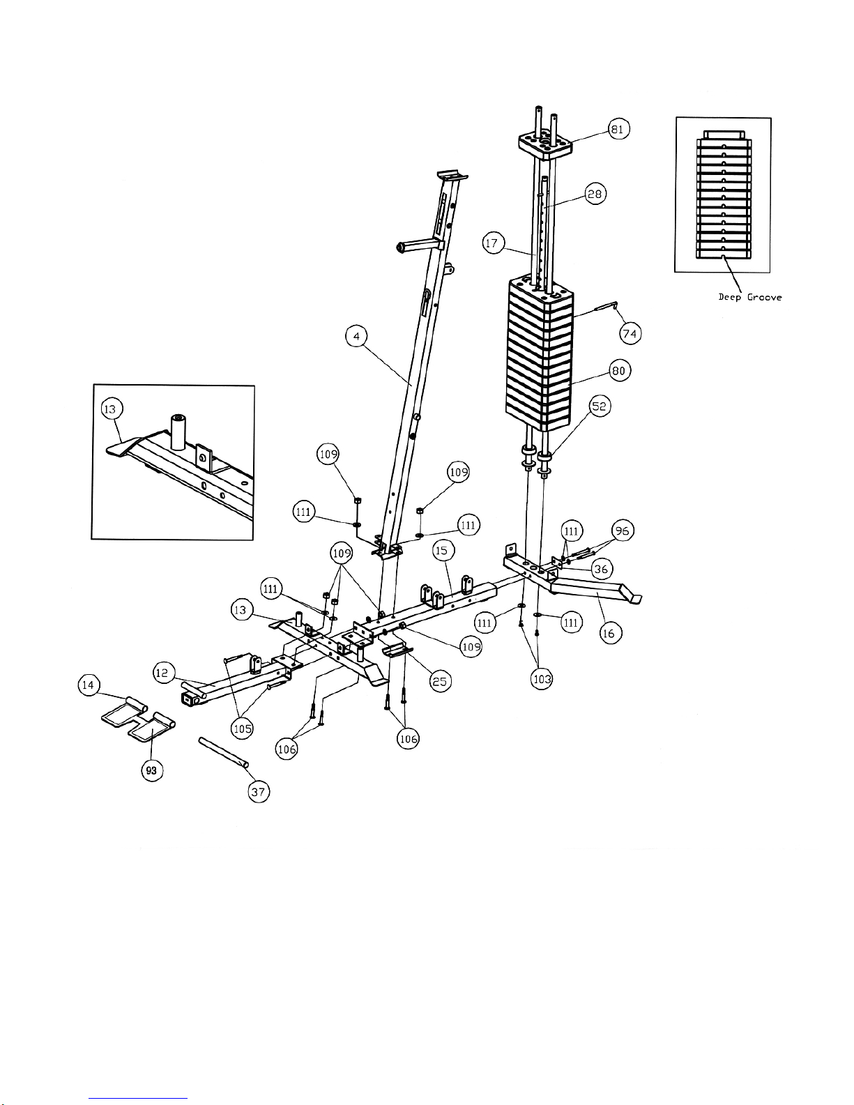
3. Periodically, spray the Guide Rods # 17 with silicon spray or light oil to ensure a smooth
operation.
4. Failure to examine the Gym regularly may affect the safety level of the equipment.
5. Maximum user weight is 140kg.
6. Assembled Dimensions: L 190 x W 127 x H 209 cm
WARNING: BEFORE BEGINNING ANY EXERCISE PROGRAM, CONSULT YOUR
PHYSICIAN. THIS IS ESPECIALLY IMPORTANT FOR INDIVIDUALS OVER THE AGE OF
35 OR PERSONS WITH PRE-EXISTING HEALTH PROBLEMS. READ ALL INSTRUCTIONS
BEFORE USING ANY FITNESS EQUIPMENT. ESCALADE ASSUMES NO RESPONSIBILITY
FOR PERSONAL INJURY OR PROPERTY DAMAGE SUSTAINED BY OR THROUGH THE
USE OF THIS PRODUCT.
SAVE THESE INSTRUCTIONS. 2

WARNING LABEL PLACEMENT
3

HARDWARE PACK
NOTE: The following parts are not drawn to scale. Please use your own ruler to measure the size.
4

HARDWARE PACK
NOTE: The following parts are not drawn to scale. Please use your own ruler to measure the size.
5
(Qty 74)

HARDWARE PACK
6

ASSEMBLY INSTRUCTION
Tools Required for Assembling the Machine: Two Adjustable Wrenches and Allen
Wrenches
NOTE: It is strongly recommended that two or more people assemble this machine to
avoid possible injury.
STEP 1 (See Diagram 1)
A.) Insert two Guide Rods (#17) into the holes on Rear Stabilizer (#16). Secure each Guide
Rod with one M10 x ¾” Allen Bolt (#103) and Ø ¾” Washer (#111) from the bottom.
Slide two Ø 2 3/8” x 1” Rubber Bumpers (#52) onto the two Guide Rods.
B.) Do not tighten the Nuts and Bolts starting from the following procedures until
instructed to do so.
C.) Attach the Vertical Frame (#4) onto the Rear Base Frame (#15). Secure it with two M10
x 2 5/8” Carriage Bolts (#106), one 4 ¾” x 2 ¾” Bracket (#25), two ∅¾” Washers
(#111), and two M10 Aircraft Nuts (#109).
D.) Attach the Butterfly Base (#13) to the Rear Base Frame (#15). Attach the Front Base
Frame (#12) to the Butterfly Base (#13). Make sure the L shaped bracket welded on the
Butterfly Base (#13) face towards the front of the machine (see small diagram in the
square insert in Diagram 1). Align the holes and secure them together with two M10 x
2 5/8” Carriage Bolts (#106) from the bottom, two M10 x 3 5/8” Carriage Bolts (#105)
from the side of Butterfly Base, four Ø ¾” Washers (#111), and four M10 Aircraft Nuts
(#109).
E.) Connect the Rear Base Frame (#15) to the Rear Stabilizer (#16). Secure them together
with two M10 x 3 5/8” Allen Bolts (#96), two Ø ¾” Washers (#111), and one 2 ¾” x 1 ½”
Bracket (#36).
F.) Attach the Foot Plate (#14) to the Front Base Frame (#12). Align the holes and insert the
Foot Plate Axle (#37) through the holes.
G.) Slide 14 Weight Plates (#80) onto the Guide Rods. Make sure the deep groves on all
Plates face down and toward the back. Insert the Selector Rod (#17) through the
center hole on the Weight Plates. Slide the Weight Selector Stem (#81) onto the Guide
Rods.
H.) Use the Weight Plate Selector Pin (#74) to select desired number of Weight Plates to
exercise. NOTE: Each Plate weights approximately 4.5kgs. Please refer to the Weight
Resistance Chart on page 28.
7

DIAGRAM 1
8

STEP 2 (See Diagram 2)
A.) Attach the Upper Frame (#1) onto the two Guide Rods (#17). Secure it with two M10 x
¾” Allen Bolts (#103) and ∅¾” Washers (#111). DO NOT tighten the Bolts yet.
B.) Place the Upper Frame onto the Vertical Frame (#4). Secure it with two M10 x 2 5/8”
Carriage Bolts (#106), one 4 ¾” x 2 ¾” Bracket (#25), two ∅¾” Washers (#111), and
two M10 Aircraft Nuts (#109).
C.)Securely tighten all Nuts and Bolts previously installed in Step-1 and Step-2.
D.)Attach the Seat Support Frame (#7) to the Vertical Frame (#4). Secure it with two M10 x
2 5/8” Carriage Bolts (#106), one 4 ¾” x 2 ¾” Bracket (#25), two ∅¾” Washers (#111),
and two M10 Aircraft Nuts (#109).
E.) Attach the Leg Developer (#8) to the bracket on the Seat Support Frame. Secure it with
one Leg Developer Axle (#19), two M10 x ¾” Allen Bolts (#103), and two Ø ¾” Washers
(#111). Do not over tighten the Bolts. Make sure the Leg Developer is able to swivel.
DIAGRAM 2
9

STEP 3 (See Diagram 3)
A.) Attach the Front Press Base (#2) to the Upper Frame (#1). Secure it with one 6
¾” Front Press Base Axle (#29), two Ø 1 ¼” Washers (#70), and two M10
Aircraft Nuts (#109).
B.) Attach the Front Press (#3) to the Front Press Base. Secure it with one 7 ½”
Front Press Axle (#30), two Ø1 ¼” Washers (#70), and two M10 Aircraft Nuts
(#109).
C.) Thread the 4” T-shaped Lock Pin (#78) into the hole on the Front Press to
obtain the desired Front Press position.
D.) Attach the Backrest Board (#89) to the Backrest Support Frame (#5). Secure it
with two M8 x 1 5/8” Allen Bolts (#113) and Ø 5/8” Washers (#112).
E.) Attach the Backrest Support Frame (#5) to the Vertical Frame (#4). Secure it
with one M10 x 4 ¼” Allen Bolt (#95), two ∅¾” Washers (#111), and one M10
Aircraft Nut (#109).
F.) Thread the 6 ¼” T-shaped Lock Pin (#77) into the hole on the side of the
Vertical Frame to obtain the desired Backrest position.
10

DIAGRAM 3
11

STEP 4 (See Diagram 4)
A.) Attach the Seat Pad (#88) to the Seat Post (#6). Secure it with two M8 x 1 5/8” Allen
Bolts (#113) and Ø 5/8” Washers (#112).
B.) Insert the Seat Post into the opening on the Seat Support Frame (#7). Thread the 3
3/8” T-shaped Lock Pin (#73) into the nut on the Seat Support Frame to lock the
Seat at desired height.
C.)Insert one Foam Tube (#23) halfway through the hole on the Leg Developer (#8).
Push two Foam Rolls (#86) onto the Foam Tube from both ends. Plug two Foam Roll
End Caps (#59) into the Ends.
D.)Attach the Leg Machine Frame (#31) to the Rear Base Frame (#15). Secure it with
two M10 x 3 5/8” Allen Bolts (#96), one 5 ½” x 2” Bracket (#26), four Ø ¾” Washers
(#111), and two M10 Aircraft Nuts (#109).
E.) Attach the Rotating Cam Plate (#32) to the Leg Machine Frame (#31). Align the
holes and insert the axle on the Lever Frame (#33) through the holes. Secure it with
one Ø 1 ¼” Washer (#70) and one M12 Aircraft Nut (#110). Do not over tighten the
nut. The Lever Frame needs to swivel freely on the pivot.
F.) Adjust and secure the Lever Frame (#33) to the Cam (#32) with a 4” T-shaped Lock
Pin (#78).
G.)Insert the axle on the Lever Frame Handle (#34) into the opening on the Lever
Frame (#33). Secure it with one Ø 1 ¼” Washer (#70) and M10 Aircraft Nut (#109).
H.)Slide a 7” Swivel Tube Sleeve (#38) onto the tube on the Lever Frame Handle (#34).
I.) Push one Ø 4” Large Foam Roll (#58) onto Sleeve. Plug one Foam Roll End Cap
(#59) into the end of Handle.
J.) Slide one Foam Tube (#23) halfway through the hole on the Leg Machine Frame
(#31). Secure it with one M6x 3/8” Screw (#108). Push the 6 7/8” Grips (#67) onto
the Tube.
12

DIAGRAM 4
13

STEP 5 (See Diagram 5)
A.) Slide the Right Butterfly (#10) onto the right axle on the Butterfly Base (#13).
B.) Insert the Butterfly Handle (#9) into the pivot on the Right Butterfly. Secure it with one M10
x ¾” Allen Bolt (#103) and ∅1 ¼” Washer (#70) from the bottom.
C.)Repeat Procedures A and B above to install the other side. Do not over tighten the Bolts.
Make sure the Handles are able to swivel. DIAGRAM 5
14

STEP 6 (See Diagram 6 & Upper Cable Loop Diagram)
A.) Attach the 167” Upper Cable (#42) to the opening on the front of Upper Frame (#1).
Make sure the ball stopper is underneath the Frame. Attach a Pulley (#44) to the Cable.
B.) Secure the Pulley to the opening with one M10 x 3 3/8” Allen Bolt (#97), two Pulley
Bushings (#53), and one M10 Aircraft Nut (#109).
C.) Draw the Cable over the Pulley along the Upper Frame towards the back of the
machine to the opening in the middle of Upper Frame. Repeat Procedure B above to
install a Pulley.
D.) Draw the Cable around the Pulley then back to the upper opening on the Front Press
Base (#2). Attach a Pulley to the opening. Secure it with one M10 x 6 ½” Allen Bolt
(#94), two ∅¾” Washers (#111), and one M10 Aircraft Nut (#109).
E.) Draw the Cable around the Pulley then towards the upper opening on the Vertical
Frame (#4). Repeat Procedure B above to install a Pulley.
F.) Draw the Cable around the Pulley and back to the lower opening on the Front Press
Base. Repeat Procedure D above to install a Pulley.
G.) Draw the Cable around the Pulley then to the lower opening on the Vertical Frame.
Repeat Procedure B above to install a Pulley.
H.) Draw the Cable underneath the Pulley then pull upward to the last opening on the back
of the Upper Frame. Repeat Procedure B above to install a Pulley.
I.) Draw the Cable around the Pulley then downward. Attach a Pulley to the top hole on
the Double Floating Pulley Brackets (#20).
J.) Secure the Pulley to the brackets with one M10 x 1 ¾” Allen Bolt (#99), two Ø ¾”
Washers (#111), and one M10 Aircraft Nut (#109). Let the Bracket hanging for now.
K.) Draw the Cable around the Pulley then upward to the open bracket between the two
Guide Rods. Repeat Procedure J above to install a Pulley.
L.) Draw the Cable around the Pulley then downward to the Selector Rod (#28). Securely
thread the Head Bolt at end of the Cable into the Selector Rod.
15

DIAGRAM 6
16

Upper Cable Loop Diagram
17

STEP 7 (See Diagram 7 & Lower Cable Loop Diagram)
A.) Attach the 215” Lower Cable (#40) to the opening on the Leg Developer (#8). Attach
a Pulley (#44) to the opening. Secure it with one M10 x 2 ½” Allen Bolt (#98), two ∅
7/8” Leg Developer Pulley Bushings (#56), and one M10 Aircraft Nut (#109).
B.) Draw the Cable underneath the Pulley to the open bracket on the Front Base Frame
(#12). Attach a Pulley to the bracket. Secure it with one M10 x 1 ¾” Allen Bolt (#99),
two ∅¾” Washers (#111), and one M10 Aircraft Nut (#109).
C.) Draw the Cable underneath the Pulley towards the back of the machine through the
bottom opening on the Vertical Frame (#4) to the open bracket on the Rear Base
Frame (#15). Repeat Procedure B above to install a Pulley.
D.) Draw the Cable underneath the Pulley then pull upward to the Double Floating Pulley
Bracket (#20) previously installed in STEP-6. Repeat Procedure B above to install a
Pulley. After completing the entire cable system, come back to the Double Floating
Pulley Bracket and adjust the height of the lower Pulley to adjust the tightness of the
Cables. Move up the pulley to increase the tension. Move down the pulley to loose
the tension.
E.) Draw the Cable around the Pulley then downward. Attach the Cable to a Single
Floating Pulley Bracket (#18). Repeat Procedure B to install a Pulley.
F.) Draw the Cable around the Pulley then upward to the open bracket on the back of
Vertical Frame (#4). Repeat Procedure B to install a Pulley.
G.) Draw the Cable around the Pulley then downward. Attach the Cable to an Angled
Double Floating Pulley Bracket (#27). Repeat Procedure B above to install a Pulley.
Let the Brackets hanging for now.
H.) Draw the Cable around the Pulley then upward to the opening on the Vertical Frame
(#4). Attach a Pulley to the opening. Secure it with one M10 x 3 3/8” Allen Bolt
(#97), two Pulley Bushings (#53), and one M10 Aircraft Nut (#109).
I.) Insert the Cable through a Ball Stopper (#47). Attach the Cable to a U-shape Cable
Connector (#48). Secure the Connector with one M10 x 1 1/8” Allen Bolt (#100), two
∅¾” Washers (#111), and one M10 Aircraft Nut (#109).
18

DIAGRAM 7
19
Table of contents
Other Marcy Home Gym manuals

Marcy
Marcy MWM-7119 User manual

Marcy
Marcy ECLIPSE HG5000 User manual

Marcy
Marcy RE1016 User manual

Marcy
Marcy MWM-1005 User manual

Marcy
Marcy DIAMOND ELITE MD-389 User manual

Marcy
Marcy Pro Deluxe Smith Cage User manual

Marcy
Marcy PM-10110 User manual

Marcy
Marcy SB-10100 User manual

Marcy
Marcy MWM-7119 Owner's manual

Marcy
Marcy MWM-989 User manual

Marcy
Marcy Marcy MWB/2001 User manual

Marcy
Marcy PM-842 MARCY PRO User manual

Marcy
Marcy MWM-6150 User manual

Marcy
Marcy RM413 User manual

Marcy
Marcy SB-4606 User manual

Marcy
Marcy GS 99 User manual

Marcy
Marcy MKM-1101 User manual

Marcy
Marcy PM-767 User manual

Marcy
Marcy MP-2106 User manual

Marcy
Marcy MCH 1510 User manual