WWW.MARETTI.COM
3/4
3/4
“No rights can be derived from the information provided on this Instruction Manual. Information on the Instruction Manual has been compiled with the utmost care and is updated on a continuous basis. Nevertheless Maretti cannot guarantee that all information is free of errors, complete or fully up to date.”
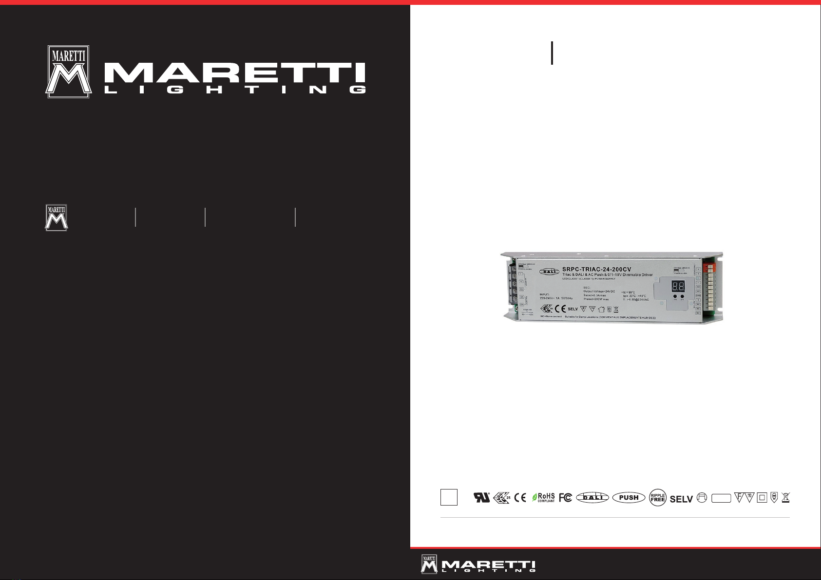
DRIVER DALI SUN 24VDC 200W 1-4CH
INSTRUCTIONS
16.9401.2420.00
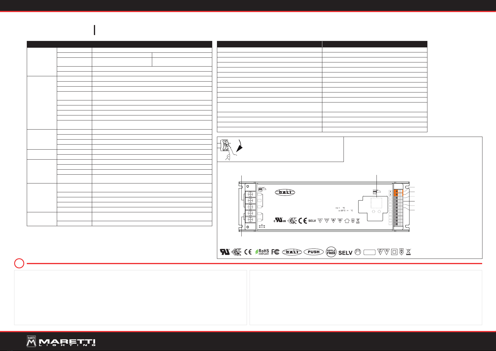
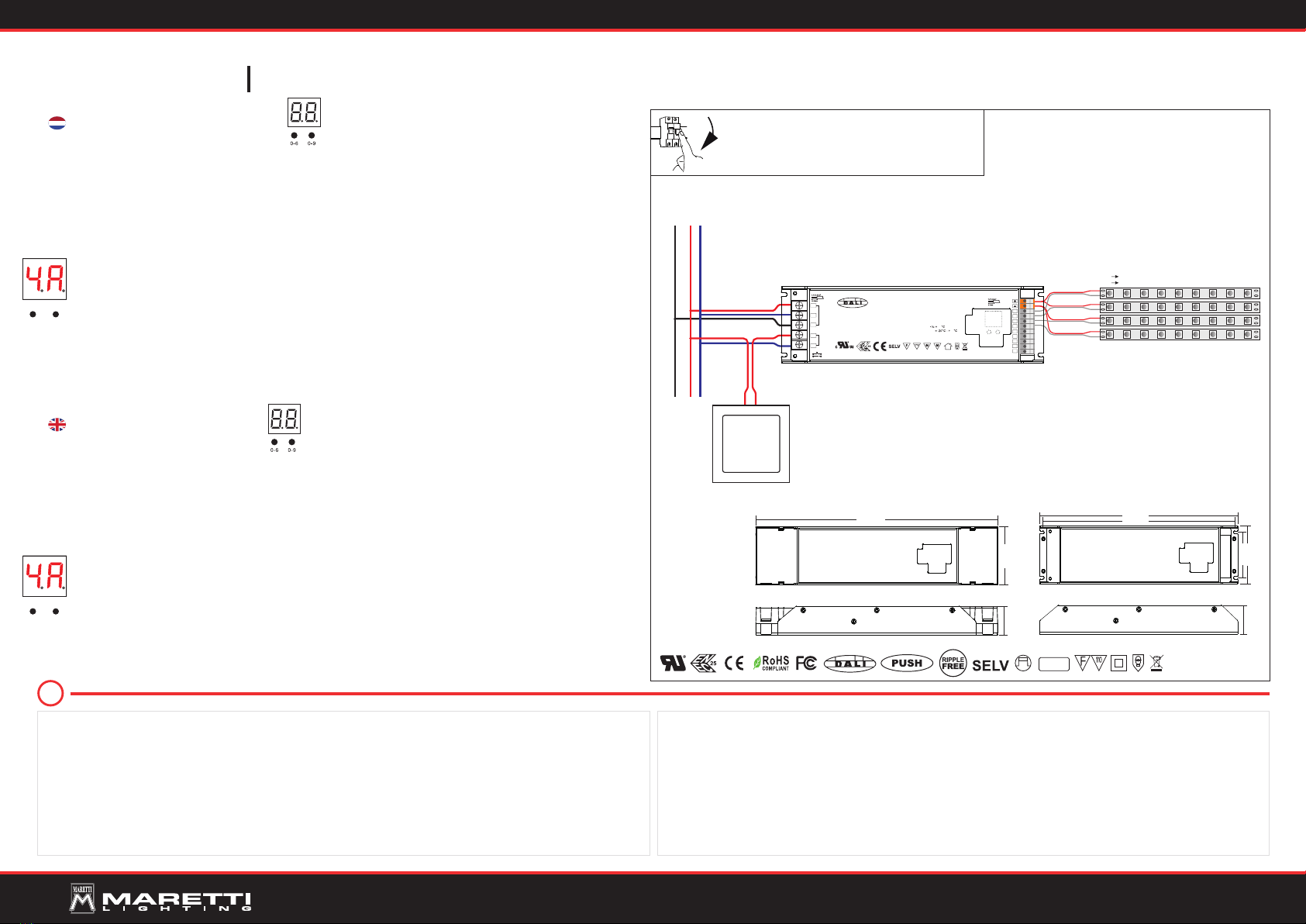
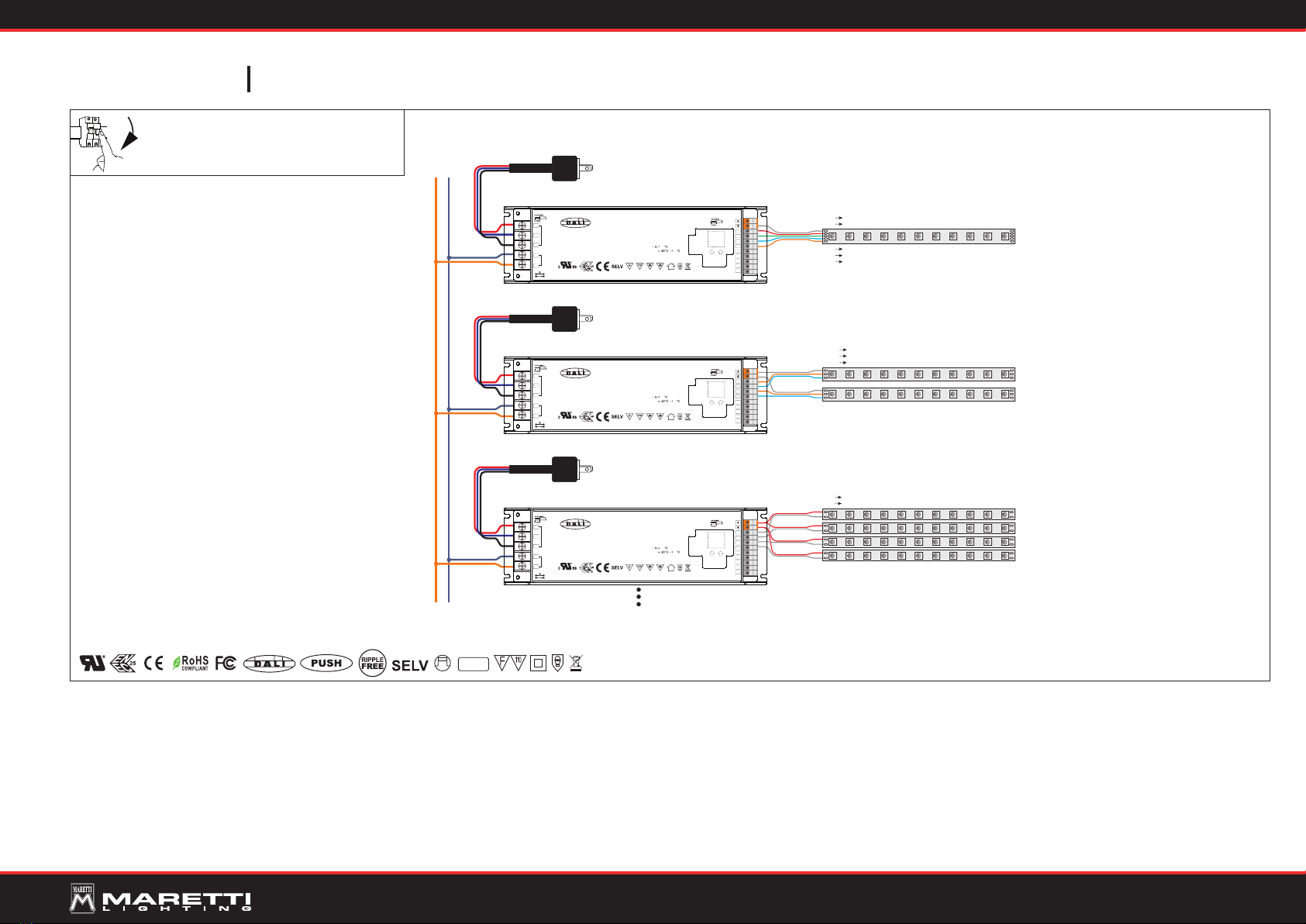
WIRING DIAGRAM
1.With PUSH dimmer
Schakel altijd eerst de stroom uit voordat u installatie-,
onderhouds- of reparatiewerkzaamheden uitvoert.
Always switch off the mains voltage before carrying
out installation, maintenance and repair work.
UIT
OFF
Product Dimension
330mm
79mm
39mm
261.7mm
270mm
62mm
79mm
39mm
Max. 100W/ CH , total p ower of 4 c han nels c an not e xc eed 200 W
V+ V+
V- V-
L NGND
PUSH
DALI Dimmabl e Dr iver
DA
DA
DALI INPU T
0-6 0-9
L
N
AC INP UT
FG 4-
1-
2-
3-
LED OUTPUT
(AWG20-1 4)
(0.24-0.28in)
SEC :
Out put Volt age=2 4VDC
Irat ed= 1x4 .16 A/2x 4.1 6A/
3x2 .75 A/4 x2. 08A
Pra ted =1x 100 W/2x 100 W/
3x6 6W/ 4x5 0W
INP UT:
100 -24 0V~ 2 .3A 50/6 0Hz
277 V~ 0. 806 A 5 0/6 0Hz
(27 7V~fo r North Am erica o nly)
NC= None co nnect S uita ble for D amp Loc ation s (CONV IENT AUX E MPLAC EMENT S HUMID ES)
E493567
ta
λ>0.95@230VAC:
85
45
(AWG18-1 4)
(0.55-0.86in)
NC
NC
NC
NC
NC
PUSH D IM
L
N
DA
DA
emc
300MHz
“No rights can be derived from the information provided on this Instruction Manual. Information on the Instruction Manual has been compiled with the utmost care and is updated on a continuous basis. Nevertheless Maretti cannot guarantee that all information is free of errors, complete or fully up to date.”
!
LET OP:
-Volg en bewaar deze gebruiksaanwijzing.
-Zorg ervoor dat de netspanning uitgeschakeld is voor installatie, reparatie of onderhoud. (Installatie, reparatie en onderhoud uitsluitend door gekwalificeerde personen).
-Voor reparatie of onderhoud uitsluitend originele delen gebruiken.
-Gebruik het armatuur alleen binnenshuis.
-Het armatuur niet in vochtige of natte ruimte gebruiken.
De fabrikant aanvaardt geen enkele aansprakelijkheid voor letsel of schade als gevolg van een verkeerde toepassing van het armatuur.
De fabrikant aanvaardt geen garantie in geval van het niet behandelen van de lampen volgens de richtlijnen van de fabrikant.
Als er schade aan elektrische onderdelen te vinden zijn, vraag dan een elektricien om het te vervangen.
Onderhoud is behoud:
Een goede instandhouding van het armatuur is sterk afhankelijk van omgevings- en onderhoudsfactoren. Hierop kunnen wij geen invloed uitoefenen.
-Schakel voor de zekerheid de elektriciteit uit!
-Gebruik geen bijtende, chemische of schurende schoonmaakmiddelen.
NOTE:
-Follow and keep this instructions manual.
-Make sure that the mains voltage is switched off for installation, reparation or maintenance. (Installation, reparation and maintenance only by qualified persons).
-Use only original parts for repairs or maintenance.
-Use the fixture only indoors.
-Don’t use the fixture in humid or wet areas.
The manufacturer accepts no liability for any injuries or damages resulting from the incorrect use or installation of the fixture.
Any operation performed on the fixture that is not in accordance with instructions will void manufacturer’s warranty.
If you find any damage to the electrical parts, please ask a qualified electrician to replace it.
Maintenance is preservation:
A good preservation of the fixture is highly dependent on environmental factors and maintenance. We cannot exercise any influence on this.
-Make sure that the mains voltage is switched off before you begin.
-Do not use strong, chemicals or abrasive cleaners.
Operation
1. Set DALI address manually via buttons
1.1 Press and hold down any of the two buttons until numeric digital display flashes, then release the button.
1.2 Click any of the two buttons once to select a digit, click again to change the digit until the desired DALI address appears. Click first button to set “tens”
position and second button to set “units” position. The address can be set from 00~63.
1.3 Then press and hold down any of the 2 buttons until the numeric digital display stops flashing to confirm the setting.
Note: DALI address can be manually assigned from 00-63-FF, by factory defaults, no DALI address is assigned for the driver, and the display shows FF . Set-
ting DALI address as FF will reset the dimmer to factory defaults.
2. DALI Address Assigned by DALI Masters
2.1 DALI address can also be assigned by DALI Master controller automatically, please refer to user manuals of compatible DALI Masters for specific operations.
Note:The digital display will show AU when the DALI master is assigning addresses.
3. Set DALI Address Quantity
3.1 Press and hold down both of the two buttons until numeric digital display flashes, then release the button.
3.2 Click first button to select “1A”, “2A”, “3A” or “4A” which means 1, 2, 3 or 4 addresses.
3.3 Then press and hold down any of the 2 buttons until the numeric digital display stops flashing to confirm the setting.
For example, when we set address to 22:
When select 1A, both 4 channels will be the same address 22.
When select 2A, channel 1&3 will be address 22, channel 2&4 will be address 23.
When select 3A, channel 1, 2, 3 will be address 22, 23, 24 respectively, channel 4 will be address 22.
When select 4A, channel 1, 2, 3, 4 will be address 22, 23, 24, 25 respectively.
4. PUSH Mode
While connected with a AC push switch, the digital display will show “PD” which means Push Dimmer Mode, operations under PUSH Dimmer Mode are
as follows:
4.1 Click the button to switch ON/OFF
4.2 Press and hold down the button to increase or decrease light intensity to desired level and release it, then repeat the operation to adjust light intensity
to opposite direction.The dimming range is from 1% to 100%.
4.3 Memory function after power off or power failure enables the device to memorize the status before power off while power on again.
De werking
1. Stel het DALI-adres handmatig via knoppen
1.1 Houd een van de twee knoppen ingedrukt totdat het numerieke digitale display knippert en laat de knop vervolgens los.
1.2 Klik op een van de twee knoppen tegelijk om een cijfer te selecteren, klik opnieuw om het cijfer te wijzigen totdat het gewenste DALI-adres verschijnt. Klik op
de eerste knop om de “tientallen” positie in te stellen en de tweede knop om de “eenheden” positie in te stellen. Het adres kan worden ingesteld vanaf 00~63.
1.3 Houd vervolgens een van de 2 knoppen ingedrukt totdat het numerieke digitale display stopt met knipperen om de instelling te bevestigen.
Let op: DALI adres kan handmatig worden toegewezen van 00-63-FF, door fabrieksinstellingen, er is geen DALI adres toegewezen aan de driver en het display
toont FF . Als u het DALI-adres instelt als FF wordt de dimmer teruggezet naar de fabrieksinstellingen.
2. DALI adres toegewezen door DALI masters
2.1 DALI-adres kan ook automatisch door de DALI Master-controller worden toegewezen, raadpleeg de gebruikershandleidingen van compatibele DALI-
master voor specifieke bewerkingen.
Let op: Het digitale display toont AU wanneer de DALI master adressen toewijst.
3. Set DALI Address Quantity
3.1 Houd beide beide knoppen ingedrukt totdat het numerieke digitale display knippert en laat de knop vervolgens los.
3.2 Klik op de eerste knop om te selecteren “1A”, “2A”, “3A” or “4A” wat betekent 1, 2, 3 or 4 adressen.
3.3 Houd vervolgens een van de 2 toetsen ingedrukt totdat het numerieke digitale display stopt met knipperen om de instelling te bevestigen.
Bijvoorbeeld wanneer we het adres instellen op 22:
Als u 1A selecteert, zijn beide 4 kanalen hetzelfde adres 22.
Wanneer u 2A selecteert, is kanaal 1 & 3 adres 22, kanaal 2 & 4 is adres 23.
Wanneer u 3A selecteert, is kanaal 1, 2, 3 het adres 22, 23, respectievelijk 24, kanaal 4 is adres 22.
Als u 4A selecteert, zijn kanaal 1, 2, 3, 4 respectievelijk adres 22, 23, 24, 25.
4. PUSH-modus
Wanneer verbonden met een AC push schakelaar, toont het digitale display “PD”, wat betekent Push Dimmer Mode, operaties onder PUSH Dimmer Mode
zijn als volgt:
4.1 Klik op de knop om AAN / UIT te schakelen
4.2 Houd de knop ingedrukt om de lichtintensiteit naar het gewenste niveau te verhogen of verlagen en laat deze los,
herhaal dan de bewerking om de lichtintensiteit in tegenovergestelde richting aan te passen. Het dimbereik is van 1% tot 100%.
4.3 Geheugenfunctie na stroomuitval of stroomstoring stelt het apparaat in staat om de status te onthouden voordat het apparaat wordt uitgeschakeld terwijl de
stroom weer wordt ingeschakeld.
1 2
1 2