Mark Secure 1 User manual

English translation of the original German
instruction manual
Keep for future reference
Version 1.2
MARK Secure 1 Instruction manual
Anchor point for drywall wall & attachment shell socket installation
Anchor device type A according to EN 795:2012
MARK Save A Life GmbH
Gleinkerau 23
4582 Spital am Pyhrn
Österreich / Europa
Tel +43 7563 8002 - 111
Fax +43 7563 8041 - 111
www.savealife.at

Dear Customer,
Congratulations on purchasing this product from MARK
Save A Life GmbH. We have manufactured and tested
this product with the utmost care, keeping to the strictest
quality guidelines, and therefore created the basis for safe
use. Now it is over to you to make sure it is used correctly.
Activities that require use of this product can often be
dangerous. There are also many potential ways of using
it incorrectly and it is not possible for us to state them
all here or even to come up with an exhaustive list. This
instruction manual contains information pertaining to the
safety and function of this product and its applications.
However, this information is no substitute for experience,
personal responsibility and knowledge, nor does it release
the user from their own individual risk.
You may only use this product if you are physically
and mentally capable of doing so, if you have read and
understood this instruction manual and the installation
report, and if you have undergone training on the use of
the product.
The instruction manual, the installation report and
the inspection report are available to download at
www.savealife.at.
Read through the instruction manual carefully
before you use this product for the rst time.
Undergo training on the use of this product.
Check this product for proper function before and
after each use.
Complete the installation report included with the
product carefully.
Always keep the instruction manual, the installa-
tion report and the inspection report together with
the other relevant product documents for future
reference.
Do you have questions about this product? Do you
have any requests or suggestions? Just give us a call
or send us an email!
Customer Service:
MARK Save A Life GmbH
Gleinkerau 23
4582 Spital am Pyhrn
Austria/Europe
Tel.: +43 (0) 7563 8002 111
Fax: +43 (0) 7563 8041 111
www.savealife.at
Manufacturer:
MARK Save A Life GmbH
Gleinkerau 23
4582 Spital am Pyhrn
Country of origin: Austria
Contents
Legal information ................................................. 4
Use ............................................................ 4
Overview, scope of delivery and technical details ......................... 7
MARK Secure 1 installation instructions ................................ 9
Transport and storage............................................. 13
Maintenance and cleaning ......................................... 13
Testing ........................................................ 13
Disposal ....................................................... 14
Resale......................................................... 14
Accidents ...................................................... 14
Installation reports................................................ 16
Inspection report ................................................. 19
23

1. Legal information
1.1 Declaration of compliance
The manufacturer, MARK Save A Life GmbH, Gleinkerau
23, 4582 Spital am Pyhrn, Austria, hereby declares that the
product described below, “MARK Secure 1”, complies with
the requirements formulated in EN 795:2012 anchor point
type A, which is also the subject of the inspection report
number ZP/B141/17-R1.
Type approval testing by: DEKRA Exam GmbH,
Dinnendahlstraße 9, 44809 Bochum, Germany.
1.2 Labelling
Your product is labelled with a batch number.
Assign your product an inventory number and enter it in the
installation report.
Do not remove any labels from your product!
Manufacturer
Product standard
Personal authorisation
Type designation
Year of manufacture
1.3 Exclusion of product liability
We accept no liability for direct, indirect or accidental
consequences, nor any type of damage arising from the
use of this product or from incorrect information provided
by the competent inspector or installation engineer on the
installation report or the inspection report.
1.4 Copyright notice
The layout, graphics, pictograms and photographs, as well
as all other text and image content found in this instruction
manual are protected by copyright.
2. Use
Activities that require use of this product can often be
dangerous. Therefore observe the safety notices. Please
contact our customer service if you have any doubts or nd
the information difcult to understand. Ensure that the fall
space is calculated so that in the event of a fall you do not
hit an obstacle or impact on the oor.
Protect the product from sharp-edged objects,
welding sparks, sources of re, chemicals, oils,
acids, etc.
Draw up a rescue plan that includes the sequence
and the execution of rescue measures.
2.1 Intended use
This product may only be used for the purpose described
in this instruction manual (see Point 2.1.1) and only in
conjunction with tested and approved components. It must
not be combined with other components, as this could put
your safety at risk. MARK Secure 1 must be used with
Knauf system components or with similar products with the
same properties.
You may only use this product if you are physically and
mentally capable of doing so, i.e., for example, not if you
are under the inuence of drugs or alcohol, are suffering
from mental strain or have other mental or physical
impairments. In any case, the intended use as protection
against a fall from height requires full physical and mental
aptitude.
2.1.1 Purpose of the product as an anchor device
according to EN 795:2012 type A
The product may be used within the intended use conditions
on the specied wall and attachment shell systems from
Knauf Gesellschaft m.b.H., or similar products with the
same properties, for the intended purpose as protection
against a fall from height.
Note:
This product is an anchor device, the purpose of which
is to protect the user from a fall from height, either by
preventing a fall (restraint system) or by arresting a
free fall (fall arrest system).
The MARK Secure 1 anchor point is intended for use as
an anchor device in conjunction with personal protective
equipment (PPE) recommended by MARK Save A Life
GmbH (retractable fall arrest blocks, safety overalls and
connectors from MARK Save A Life).
Classed as tested accessories: Test standard
Descender and rescue devices
Lifting devices
Retractable fall arrest blocks
Guided-type fall arresters on
flexible anchor lines
Energy absorbers
Carabiners
Safety harnesses
Safety nets
EN 341
EN 1496
EN 360
EN 353-2
EN 355
EN 362
EN 361
EN 1263
If it seems unsafe to continue using this product, (see Point
8.1) you must not use it again under any circumstances.
Before every use of the product, the user must carry out
a visual inspection according to Point 7 of this manual to
ensure that the product is in serviceable condition.
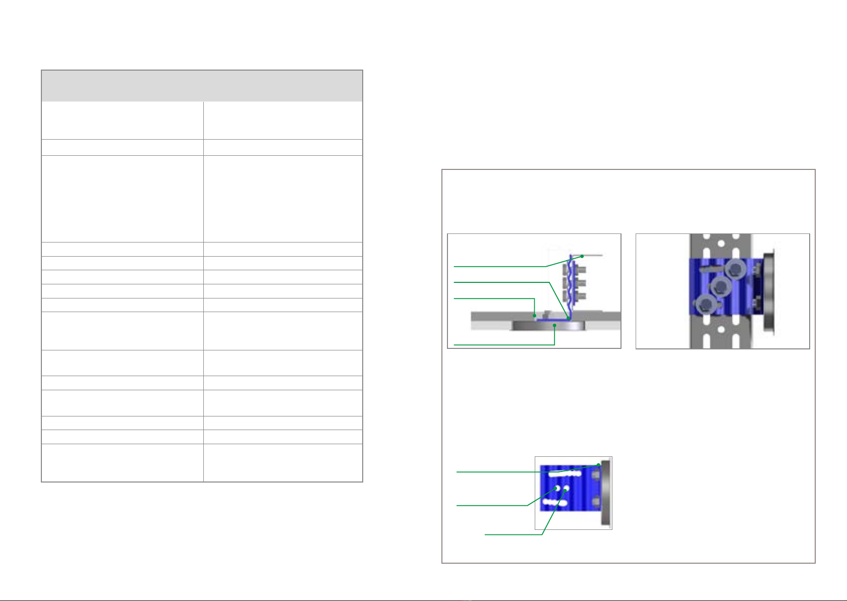
2.1.2 Use of the anchor point
In order to use the anchor point, the buckle is released
from the lock and folded up. The connector of the PPE can
be suspended.
In principle, the load from a fall from height may be in any
direction protruding from the wall surface or parallel to the
wall.
The length of the connector used must be selected so that
in each case the possible fall space is free of obstacles.
The total position change of the anchor point to be
expected in the event of a fall from height (consisting of
the deformation of the metal stud partition or attachment
shell and the anchor point itself) is a maximum of 15 cm
in the event of a vertical load direction parallel to the wall
surface.
If there is a fall-related load when a person falls vertically
to the wall surface (e.g. in the event of an unintentional
redirection of the load), it must be anticipated that there will
be a total position change of the anchor point (consisting
of the deformation of the metal stud partition or attachment
shell and the anchor point itself) of a maximum of 15% of
the respective wall height.
2. Fold up buckle
Working position
3. Fold buckle down
after use
4. Move buckle into lock
1. Move buckle out of lock
45
Read instruction manual
Batch number
CE marking

3. Overview, scope of delivery and technical details
3.1 Overview
3.2 Scope of delivery:
A
B
C
D
E
F
G
1 x MARK Secure anchor point
1 x absorber
(incl. centring hole)
1 x socket
2 x stainless-steel screws
countersunk head M10 x 20
4 x deformation brackets
2 x counterplates (2-hole)
1 x counterplate (3-hole)
H
I
J
K
4 x Fischer bolt anchor FAZ M12 incl.
washers and nuts
7 x screws M8 x 25 8.8 galvanised
7 x washers 8.4 x 25 galvanised
Knauf UA profile 75 x 40 x 2 mm
or similar product with the same
properties
(not included in the scope of delivery)
H
H
E
E
G
B
I
I
K
J
J
H
E
I
J
A
C
E
D
F
F
H
intended use.
When using the product, the user must be kitted out
with equipment that limits the maximum dynamic forces
that impact on their body during a fall arrest process to a
maximum of 6 kN.
2.2 Service life and duration of use
This product has an unlimited service life. In practice,
however, its duration of use depends on several factors.
• Extreme operating conditions, environmental factors,
contamination, damage, storage and transport can
all reduce the service life of this product.
• The product features a fall indicator, which clearly
shows whether the anchor device has been
subjected to the stress of a fall and must therefore
be disposed of as per Point 8.
• The visual and functional inspection described in
Point 7 shows every user whether the anchor device
has been deformed by a previous fall and therefore
can no longer be used.
If the anchor point buckle will no longer engage easily
in its home position or move easily from its home
position to its working position, then the anchor
device has been deformed by a previous fall and must
no longer be used.
2.3 Qualication of persons
This product may only be used by people who have read
and understood this instruction manual, or by people who
are being supervised by a trained, skilled person.
2.4. Training
We would be happy to provide you with information about
training. If you are interested, please contact us:
MARK Save A Life GmbH
Gleinkerau 23
4582 Spital am Pyhrn
Austria/Europe
Tel.: +43 (0) 7563 8002 111
Fax: +43 (0) 7563 8041 111
www.savealife.at
67

4. MARK Secure 1 installation instructions
Drywall wall & attachment shell socket installation
Anchor device type A according to EN 795:2012 for
installation on metal stud partitions and attachment shells
of types Knauf W112.at, W113.at, W115.at, W116.at and
W626.at or similar products with the same properties. Use
on AQUAPANEL® wall systems is also possible. Suitable
for vertical and horizontal load due to a fall from height.
Maximum expected total deformation of the installation
base and the anchor point due to a fall from a height:
15 cm vertical, 80 cm horizontal (in the event of a wall
height of 5 m). Adjust the length of the connector based on
conditions on site!
Installation:
This product may only be installed as per this instruction manual. MARK Save A Life GmbH recommends it is installed by
a specialist company..
2. The absorber Band the counterplate (3-hole) Gmust
be secured to a central (circular) hole and two slots
in the UA profile K(3 x I& 3 x J).
The height for installing the absorber can be adjusted
in 5 cm increments (spacing of the round holes).
The top of the absorber Bis marked with the imprint
TOP, meaning that when it is installed correctly the
centre of the absorber Bis in the wall surface 30 mm
to the left of the UA profile K.
1. The UA profile Kis always placed so that its back
points towards the left (see diagram). Transfer the-
position of the anchor point Afrom the plan into real-
life. The back of the UA profile Kis positioned 30 mm
to the right of the position of the anchor point accor-
ding to the plan.
Absorber B
UA-profile K 75mm
Socket with anchor point MARK Secure 1
Cladding, e.g. 2×12,5 GKB
3.3 Technical details
Installation base, components,
tools, operating conditions
Approved for Knauf systems or similar products
with the same properties
W112.at, W113.at, W115.at, W116.at, W626.at,
Knauf AQUAPANEL®: W382.at, W385.at,
W386.at, W686.at
Test standard, permissible number of people EN 795:2012, 1 person.
Fasteners 2 x stainl.-steel screws, counters. head M10x20
4 x deformation brackets
4 x Fischer FAZ II 12/10
7 x screws M8 x 25 8.8 galvanised
7 x washers 8.4 x 25 galvanised
2 x counterplates 2-hole
1 x counterplate 3-hole
Drill Masonry drill bit 12 mm
Screw-in depth 100 mm
Hole cutter 95 mm with centring drill 6 mm
Torque wrench 13 mm nut and 19 mm nut, Allen socket 6 mm
Tightening torques M8: 27 Nm, M10: 20 Nm, M12: 60 Nm
Quality of the installation base
(static load-bearing capacity of the structure
must be guaranteed)
≥ C 20/25
Addition Installation only on load-bearing components:
Ceiling and unfinished floor
Distance from edge ≥ 55 mm
Thickness of non-load-bearing cladding
(plasterboard, insulation)
2-3 layer cladding 12,5mm
Permissible load directions Horizontal, vertical
Wall height 1,0 - 5,0 m
Maximum expected deformation due to a fall
from a height
≤ 150 mm in the event of vertical load
≤ 800 mm in the event of horizontal load in the
middle of the wall (wall height = 5 m)
Fig. Horizontal section
Use this hole for
double-layer cladding
Use this hole for triple-layer
cladding
TOP
89

8. Align the deformation bracket Eto the slots of the UA
profile K, in which case the position of the M8 screws
Iand the counterplates Fmust always be selected so
that it is as far as possible towards the end of the un-
dulating side of the relevant deformation bracket E.
The M8 screws I must not be inserted at the open
end of the slots of the UA profile K. If open slots at
the end of the UA profile Kare unavoidable, then the
next slot pair with closed ends must be used.
3. Push the UA profile Kinto the UW connection profile
on the ceiling and unfinished floor and align to be
precisely perpendicular with the back of the profile
30 mm to the right of the position of the anchor point
Aaccording to the plan.
4. Position the four deformation brackets E, each with
the undulating side pointing towards the UA profile K
at its upper and lower end, align the UA profile Kand
mark the anchor holes on the unfinished ceiling and
floor (see Overview 3.1).
5. Drill two anchor holes each in the unfinished ceiling
and floor to a depth of 110 mm.
6. Clean the drilled holes and position the anchor H
(FAZ M12).
7. Insert the deformation brackets E(see Overview 3.1)
and loosely tighten M12 nuts of the concrete anchors
H. This means that the deformation brackets Ecan
still easily be aligned to the UA profile K.
9. Insert 2 screws Ieach at the top and bottom on the
UA profile Kand secure the deformation brackets E
using the counterplates Fwith the maximum permit-
ted torque (27 Nm).
10. Tighten the M12 nuts on the anchors Hat the top
and bottom (torque 60 Nm).
11. Prepare the first plate position, calibrate and mark
the position of the absorber B.
10 11

12_13
12. The opening for the absorber Bis cut out in the first
plate position using a keyhole saw in a rectangle of
approx. 70 x 45 mm, meaning that the first plate po-
sition is solidly on the substructure and can be se-
cured. The absorber Bsits flush with the reverse of
the relevant ceiling cladding.
Install the first ceiling cladding layer and level out. In
the event of triple-layer cladding, also cut out and
install the second cladding layer as described above.
13. Adjust the relevant ceiling cladding, calibrate the
centre of the absorber B(central 6 mm hole) to the
correct position and mark as precisely as possible on
the prepared plate. Cut out a roughly coin-sized
opening at the marked position. Secure the ceiling
cladding to the substructure.
14. Align the hole cutter with 6 mm guide drill with the
central hole of the absorber Band cut out the hole
from the ceiling cladding. When doing so, do not cut
into the cladding layer(s) underneath. Remove the
round cut-out and level out the wall/attachment shell.
15. Completion:
After levelling out the wall/attachment shell, insert
socket Cinto the socket hole and secure anchor
point Ausing the two countersunk screws D. The
anchor point Ais moved so that its markings are
upright and the “front side” is visible on the buckle.
Torque max. 20 Nm.
16. Complete the installation report and inspection report
(enclosed).
Observe periodic inspections.
Observe instructions for use for MARK Secure 1 on
the following pages!
5. Transport and Storage
Store and transport this product in dry conditions and
protected e.g. against mechanical and chemical inuen-
ces.
6. Maintenance and Cleaning
If it is stored and installed correctly and not subjected to a
load, this product has an unlimited service life. The service
life may decrease depending on the type of use and
external inuences. The product must be cleaned using
water. Acidic cleaning agents must be avoided. After a fall,
the anchor device must be taken out of use (see Point 8).
6.1 Repairs
Repairs (e.g. if screws are not seated securely in the
installation base) may only be performed by specialist
companies. Only MARK Save A Life GmbH may modify
or add to the product described in this instruction manual.
6.2 Spare parts
If you need spare parts, please contact.
MARK Save A Life GmbH
Gleinkerau 23
4582 Spital am Pyhrn
Austria/Europe
Tel.: +43 7563 8002 - 111
Fax: +43 7563 8041 - 111
www.savealife.at
7. Testing
7.1 Installation report and inspection report
The installation report and the inspection report are
included in the product packaging and, if necessary, are
available to download at www.savealife.a
t.
Complete the installation report and inspection
report carefully.
Observe the manufacturer’s information accor-
ding to the instruction manual.
7.2 Visual and functional inspection
The visual and functional inspection is only valid subject to
the reservation that components of the product have not
been modied or altered.
1. Move buckle out of lock 2. Fold up buckle
Working position
3. Fold buckle down
after use
4. Move buckle into lock
12
13
An inspection must be carried out at least once a
year by a competent person
The visual and functional inspection requires
no involvement from external testing
authorities. Test loads do not need to be
attached.
CCheck that the product labels are legible.
If the inspection indicates that it may be unsafe
to continue using the product, you must not use it
again under any circumstances; instead, ensure
it can no longer be used (see Point 8) and replace
it.
The result of this inspection must be entered in
the inspection report.

The frequency of the inspection will depend on how often
and how intensely the product is used, as well as on the
operating environment. If the product is subjected to
extremely heavy stress, the inspection must be performed
more than once a year.
8. Disposal
MARK Save A Life GmbH is committed to protecting
the environment. We endeavour to consider the
environment when manufacturing our products and hope
that our customers will use and dispose of them in an
environmentally responsible manner.
8.2 How should you dispose of this product?
Dispose of this product in such a way that it cannot
possibly be re-used (by snapping off the buckle). Dispose
of this product as recyclable used metal, according to
national regulations and standards.
9. Resale
This product may only be resold with the instruction
manual, installation report and inspection report. The
purchaser must always be given these documents in their
respective ofcial national language. This is the seller’s
responsibility.
10. Accidents
Activities that require use of this product can often be
dangerous. There are also many potential ways of using
it incorrectly and it is not possible for us to state them
all here or even to come up with an exhaustive list. The
information below is designed to help you avoid accidents,
but is no substitute for experience, personal responsibility
and knowledge, nor does it release you from your own
individual risk.
Check the application area and fall space for po-
tential hazards before every use of this product.
Before every use, think about how rescue meas-
ures can be carried out safely and effectively (see
Point 2.1.1).
Draw up a rescue plan that covers all rescue
measures for all possible emergency situations
10.1 Suspension trauma
Suspension trauma (orthostatic shock) can occur in the
event of a fall or a lengthy descent. Suspension trauma
can cause lifelong health consequences and can even be
fatal.
10.1.1 How can you recognise suspension trauma?
Paleness, sweating
Initially, a rise in pulse and blood pressure
Shortness of breath
Impaired vision
Dizziness, nausea
A drop in pulse and blood pressure
10.1.2 What can you do to stave off suspension
trauma if you need to be rescued?
Kick one foot rmly against the other and point
the toes of the bottom foot upwards.
10.1.3 What rst aid measures can you instigate?
Call the emergency services.
Lower the person who needs to be rescued.
Place the person on the oor with the upper body
elevated (in a sitting or squatting position).
Release the straps and any restricting clothing.
Only put the person into a recumbent position
slowly.
Always pay attention to the person’s circulation
and breathing.
If the affected person is no longer displaying
signs of life, start resuscitation immediately.
Notes
14 15
8.1 When do you have to dispose of this product?
If the visual and functional inspection has identi-
ed defects.
If the buckle will no longer engage in the lock.
If it seems unsafe to continue using the product.
If there is damage (tears, cracks, etc.).
If there is deformation (e.g. caused by a fall or a
heavy load).
If it no longer complies with state-of-the-art
technology.

Installation report for MARK Secure 1
Drywall wall & attachment shell socket installation
The completed installation report for the anchor points listed below conrms that installation has been carried out
properly in line with the instruction manual for the product.
Installation situation (sketch/photo):
Construction project:
Component:
Storey/section:
Room no.:
Installer:
No. of anchor points according to plan:
16 17
Installation report for MARK Secure 1
Drywall wall & attachment shell socket installation
The completed installation report for the anchor points listed below conrms that installation has been carried out
properly in line with the instruction manual for the product.
Installation situation (sketch/photo):
Construction project:
Component:
Storey/section:
Room no.:
Installer:
No. of anchor points according to plan:

Installation
MARK Secure 1 construction kit supplied in full
Instruction manual read and understood
Unfinished floor concrete ≥ C 20/25
Unfinished ceiling concrete ≥ C 20/25
Distance of the drilled holes from the edge ≤ 55 mm
Screw-in depth of the anchor ≥ 100 mm
Drilled holes = 12 mm
All parts of the construction kit used in full
All screws tightened to nominal torque
Installation carried out according to instruction manual
Safety for use confirmed
a
Installation date:
Client/project manager Contractor/project manager
Name, company signature Name, company signature
Initial inspection 2022 2023 2024 2025 2026 2027 2028 2029 2030 2031 2032
1
2
3
4
5
6
7
8
9
10
11
12
13
Initial inspection, periodic inspections
INSPECTION REPORT/visual inspections
Anchor point type A according to EN795:2012 MARK Secure 1 - No.:
__
(If points 3-11, or for the initial inspection 1-11,
are crossed off, then 12 can be crossed off
here; otherwise 13)
Result of the
visual
inspection
Installation report completed (see reverse
Installation base solid and stable
Buckle can be opened by tapping it
All visible screws tightened to nominal torque
This product must be inspected at least once a year by a competent person, but depending on the operating environment and intensity it may need to be inspected more frequently. This inspection is only valid if
this product was installed according to the installation manual provided by the manufacturer, and if components of the product have not been modified or altered or subjected to temperatures < -40°C or > 80°C. Complete the
inspection report carefully! Keep the inspection report with the documents for future reference as per the Austrian Construction Work Coordination Act (BauKG).
Photo documentation available
Anchor point available
Instruction manual available
Installation
Annual
Buckle engages in the lock with little force
Anchor point is in perfect condition and can be used
The anchor point is damaged or no longer working
properly, has been rendered inoperative (by snapping off
and removing the buckle)
The anchor point needs to be replaced.
No corrosion can be identified on the anchor point
No cracks can be seen on the anchor point
No deformation of the anchor point can be identified
MARK Save A Life GmbH, Gleinkerau 23, 4582 Spital am Pyhrn, +43 7563 8002-111, [email protected]
Comments:
Signature of expert inspector
Next regular inspection date: Month/year
Inspection date: Month/year
18 19

Subject to technical modifications.
The latest version shall always
apply.
We only guarantee that our
materials are in perfect working
order.
All rights reserved. It is only permit-
ted to make changes to, reprint or
photographically reproduce this do-
cument, in whole or in part,
with the express consent of
MARK Save A Life GmbH,
Gleinkerau 23, 4582 Spital am
Pyhrn.
MARK Save A Life GmbH
Gleinkerau 23
4582 Spital am Pyhrn
Österreich / Europa
Tel: +43 7563 8002 111
Fax:+43 7563 8041 111
www.savealife.at
Making
your life
safer.
Table of contents
Other Mark Safety Equipment manuals