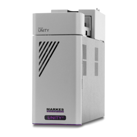
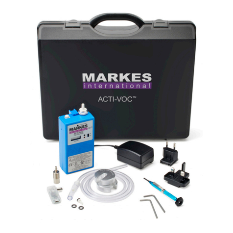
Markes International Unity 2 User manual

Markes International Ltd
T: +44 (0)1443 230935 F: +44 (0)1443 231531 E: enquiries@markes.com
www.markes.com
QUI-1057
Version 2.0 – February 2014
User manual
UNITY 2™

QUI-1057
Page 2
Markes International Ltd
T: +44 (0)1443 230935 F: +44 (0)1443 231531 E: enquiries@markes.com
www.markes.com
Contents
1. Preface ................................................................................................. 5
1.1 Notices ............................................................................................ 5
1.2 Warranty .......................................................................................... 5
1.3 Regulatory compliance .................................................................. 5
1.4 Important safety warnings ............................................................. 5
1.4.1 Labels/symbols ................................................................. 6
1.4.2 Mains voltages .................................................................. 6
1.4.3 High temperatures ............................................................ 6
1.4.4 Hydrogen gas safety ......................................................... 7
1.4.5 Cleaning and decontamination ........................................ 7
1.5 Environment operating conditions ................................................ 7
1.5.1 Temperature ...................................................................... 7
1.5.2 Humidity ............................................................................ 7
1.5.3 Altitude .............................................................................. 8
1.6 Technical Specifications ................................................................ 8
1.6.1 Physical properties ........................................................... 8
1.6.2 Electrical properties .......................................................... 8
1.7 Technical support contact details ................................................. 8
2. Instrument familiarisation .................................................................. 9
2.1 Hardware ........................................................................................ 10
2.1.1 Sample tubes .................................................................... 10
2.1.2 Tube desorption oven ....................................................... 10
2.1.3 Tube filters and seals ....................................................... 10
2.1.4 The cold trap ..................................................................... 10
2.1.5 Cold trap cooling and heating .......................................... 10
2.1.6 Trap filters and seals ........................................................ 11
2.1.7 Split filters ......................................................................... 11
2.2 Sequence of operation ................................................................... 12
2.2.1 Standby .............................................................................. 12
2.2.2 Leak test ............................................................................ 13
2.2.3 Prepurge ............................................................................ 14
2.2.4 Primary (tube) desorption ................................................ 15
2.2.5 Pre trap fire purge ............................................................. 16
2.2.6 Secondary (trap) desorption ............................................ 17
2.3 Insertion and removal of a sample tube in UNITY 2 .................... 18
2.3.1 Insertion............................................................................. 18
2.3.2 Removal ............................................................................. 18
2.4 Desorb and split flows .................................................................... 18
2.4.1 Gas flow through the cold trap ........................................ 18

QUI-1057
Page 3
Markes International Ltd
T: +44 (0)1443 230935 F: +44 (0)1443 231531 E: enquiries@markes.com
www.markes.com
2.4.2 When should desorb/split flows be measured? ............. 18
2.4.3 The Set Gas Flow function................................................ 19
2.4.4 Measuring and adjusting flows during Set Gas Flow ..... 19
2.4.5 To exit the Set Gas Flows Function .................................. 20
2.4.6 Gas flow constraints - minimum & maximum settings .. 20
2.4.7 Sample splitting ................................................................ 20
2.4.8 Analytical column capacity ............................................... 20
2.4.9 GC system detection limits ............................................... 20
2.4.10 Calculating analyte masses in the sample tube ............. 21
2.4.11 Calculating splits/split modes ......................................... 21
2.4.12 UNITY 2 systems with Electronic Carrier Control (ECC) .. 22
2.4.13 UNITY 2 systems configured with Electronic Mass
Flow Control....................................................................... 22
3. Software ............................................................................................... 23
3.1 Running the software ..................................................................... 23
3.2 Status bar ....................................................................................... 23
3.2.1 External ready signal ........................................................ 24
3.3 Toolbar functions ............................................................................ 25
3.3.1 Method Linking ................................................................. 27
3.3.2 The Trap Heat Method ...................................................... 29
3.3.3 Schematic display of UNITY 2 status ............................... 30
3.3.4 Controlling method ........................................................... 30
3.4 UNITY 2 Options.............................................................................. 30
3.4.1 Configuration ..................................................................... 31
3.4.2 GC Interface ...................................................................... 32
3.4.3 Gas & Flow ........................................................................ 32
3.4.4 Methods ............................................................................. 33
3.4.5 Reporting ........................................................................... 35
3.5 UNITY 2 method options ................................................................ 36
3.5.1 Split on or off in standby .................................................. 36
3.5.2 The Leak Test .................................................................... 36
3.5.3 Determining the prepurge time ....................................... 36
3.6 Desorption modes .......................................................................... 37
3.6.1 Tube conditioning mode ................................................... 37
3.6.2 Standard 2(3) stage desorption ...................................... 38
3.6.3 Sample tube prepurge ...................................................... 42
3.6.4 Sample tube prepurge at elevated temperature ............ 43
3.6.5 SecureTD-Q™ - Re-collection for repeat analysis ........... 43
3.6.6 Cold Trap conditioning ...................................................... 44
3.6.7 UNITY 2 parameter specifications ................................... 45
3.7 Uninstalling UNITY 2 software ....................................................... 46
QUI-1057
Page 4
Markes International Ltd
T: +44 (0)1443 230935 F: +44 (0)1443 231531 E: enquiries@markes.com
www.markes.com
3.7.1 Windows 7 ......................................................................... 46
3.7.2 Windows Vista ................................................................... 47
3.7.3 Windows XP ....................................................................... 47
4. Accessing product and support information ...................................... 48
4.1 Markes International Limited - Home Page and facilities............ 48
4.2 Consumables and Spares .............................................................. 48
4.3 Applications library ......................................................................... 48
4.4 Technical support ........................................................................... 48
5. Technical Support ................................................................................ 49
5.1 Routine maintenance schedule .................................................... 49
5.2 Sorbent Tubes ................................................................................ 49
5.2.1 Packing tubes .................................................................... 49
5.2.2 Lifespan of tubes .............................................................. 50
5.2.3 Conditioning tubes ............................................................ 51
5.2.4 Long term storage of clean and sampled tubes ............. 52
5.2.5 Changing tube seals and filters ....................................... 52
5.2.6 Changing the charcoal split tube filters .......................... 53
5.2.7 Changing DiffLok cap o-rings (UltrA) ............................... 53
5.3 Cold Trap ......................................................................................... 55
5.3.1 Packing / conditioning a cold trap................................... 55
5.3.2 Removing / replacing a cold trap .................................... 56
5.3.3 Removing / replacing a broken cold trap ....................... 61
6. Trademarks .......................................................................................... 67

QUI-1057
Page 5
Markes International Ltd
T: +44 (0)1443 230935 F: +44 (0)1443 231531 E: enquiries@markes.com
www.markes.com
1. Preface
This manual provides detailed instructions on the use of the UNITY 2. It is suitable for users with little or
no prior experience of the system and details the software/hardware interface and procedure for first
sample runs.
1.1 Notices
No part of this manual may be reproduced in any form or by any means (including electronic storage and
retrieval or translation into a foreign language) without prior agreement and written consent from Markes
International.
Please note that the material contained in this document is subject to being changed, without notice, in
future editions. Markes International shall not be liable for errors or for incidental or consequential
damages in connection with the supply, use or performance of this document or of any information
contained herein, unless a separate agreement between Markes International and the user should take
precedence.
1.2 Warranty
UNITY 2 is designed for laboratory use only. It is not intended for use in domestic establishments or
establishments directly connected to a low-voltage power supply network that supplies buildings used for
domestic purposes. Where equipment is used in a field placement environment, care must be taken to
ensure that the instrument is not exposed to detrimental conditions, i.e. rain, wind, or sun. Exposure may
diminish the performance, cause damage to the instrument and/or cause the equipment to become
unsafe to the user.
If the equipment is not used in a way specified by Markes International, the safety protection provided by
the equipment may be reduced. Furthermore, system failures arising from such use may not be covered in
standard warranty and/or service contract agreements.
1.3 Regulatory compliance
The instrument is designed and manufactured under a quality system registered to ISO 9001.
The instrument conforms to the following standards:
International Electrochemical Commision (IEC):
o 61010-1:2001.
o 61010-2-010:2003.
o 61010-2-081:2001.
CAN/CSA C22.2 No. 61010-1 and UL 61010-1.
The instrument conforms to the following regulation on electromagnetic compatibility (EMC):
o IEC/EN 61326-1:2006.
1.4 Important safety warnings
There are several important safety notices to keep in mind when installing and using this instrument.

Markes International Ltd
T: +44 (0)1443 230935 F: +44 (0)1443 231531 E:
enquiries@markes.com
www.markes.com
1.4.1 Labels/symbols
Throughout this manual symbols will appear where carrying out an operation may involve hazards.
Symbols and warnings also appear on the instrument, and these should be adhered to
Markes International can accept no liability for failure to do so.
BURN HAZARD
A hot surface may result in a burn injury.
INSTRUMENT/PART DAMAGE
Damage to the instrument or module may occur. This damage may not be covered under
the
standard warranties.
LIFTING HAZARD
Injury may occur if proper lifting procedures are not followed.
WARNING
General warning
symbol to alert the user that personal injury or instrument damage may
occur if the instrument is improperly used or if instru
DISPOSAL
This label indicates the instrument must not be disposed in regular waste but in
accordance with the WEEE scheme
1.4.2 Mains voltages
Ensure at all times that the plug (electrical isolator) can be easily and
accessed during equipment use.
The instrument must be suitably earthed via the power cord.
NOTE
: Voltages within the instrument will be a maximum of 24 V. Although there is
decreased risk of serious injury, these internal voltages should still be
as dangerous. Contact with any live parts may cause personal injury and/or
instrument damage.
1.4.3 High temperatures
Several parts of the UNITY 2
these zones whilst the system is in operation
zones are:
o Heated valve.
o Tube oven.
See Section 2 for the location of these zones. Both these zones are labelled with
‘Burn hazard’ labels similar to that shown above.
ALWAYS operate the instrument with the covers in pl
with these zones.
Throughout this manual symbols will appear where carrying out an operation may involve hazards.
Symbols and warnings also appear on the instrument, and these should be adhered to
Markes International can accept no liability for failure to do so.
A hot surface may result in a burn injury.
INSTRUMENT/PART DAMAGE
Damage to the instrument or module may occur. This damage may not be covered under
standard warranties.
Injury may occur if proper lifting procedures are not followed.
symbol to alert the user that personal injury or instrument damage may
occur if the instrument is improperly used or if instructions are not followed correctly.
This label indicates the instrument must not be disposed in regular waste but in
accordance with the WEEE scheme
.
Ensure at all times that the plug (electrical isolator) can be easily and
accessed during equipment use.
The instrument must be suitably earthed via the power cord.
: Voltages within the instrument will be a maximum of 24 V. Although there is
decreased risk of serious injury, these internal voltages should still be
as dangerous. Contact with any live parts may cause personal injury and/or
instrument damage.
Several parts of the UNITY 2
can be operated at
high temperatures
these zones whilst the system is in operation can cause serious burn injury. These
See Section 2 for the location of these zones. Both these zones are labelled with
‘Burn hazard’ labels similar to that shown above.
ALWAYS operate the instrument with the covers in place to avoid accidental contact
QUI-1057
Page 6
Throughout this manual symbols will appear where carrying out an operation may involve hazards.
Symbols and warnings also appear on the instrument, and these should be adhered to
at all times.
Damage to the instrument or module may occur. This damage may not be covered under
symbol to alert the user that personal injury or instrument damage may
ctions are not followed correctly.
This label indicates the instrument must not be disposed in regular waste but in
Ensure at all times that the plug (electrical isolator) can be easily and
quickly
: Voltages within the instrument will be a maximum of 24 V. Although there is
decreased risk of serious injury, these internal voltages should still be
treated
as dangerous. Contact with any live parts may cause personal injury and/or
high temperatures
. Contact with
can cause serious burn injury. These
See Section 2 for the location of these zones. Both these zones are labelled with
ace to avoid accidental contact

QUI-1057
Page 7
Markes International Ltd
T: +44 (0)1443 230935 F: +44 (0)1443 231531 E: enquiries@markes.com
www.markes.com
Due to the high temperatures involved in the flow path, other zones of the instrument
will be at higher temperatures during operation. These may not on visual inspection
be obvious to the user. These zones are:
o The insulation of the GC transfer line.
o Top and side covers (especially directly above the heated valve).
See Section 2 for the location of these zones.
1.4.4 Hydrogen gas safety
Hydrogen is a colourless, odourless, highly flammable gas. Hydrogen presents a
hazard as it is combustible over a variety of concentrations at ambient temperature
and pressure. It has a low ignition temperature and is very fast-burning.
If the user does use hydrogen as their carrier gas, then they do so at their own risk.
The user must ensure that all adequate safety precautions are taken and that the
installation of the hydrogen system is carried out in accordance with all applicable
codes and standards.
Markes International will assume no liability for any damage or injury caused by the
use of hydrogen.
For further advice on the use of hydrogen as a carrier gas, please contact Markes
International Technical Support.
1.4.5 Cleaning and decontamination
Please consult Markes International or your local agent for information on decontamination or the use of
cleaning agents
NOTE: Incorrect cleaning/decontamination could result in damage to the instrument.
1.5 Environment operating conditions
The instrument should be protected from conditions that could cause exposure to frost, dew, percolating
water, rain, excessive direct sunlight, etc.
Performance can be affected by sources of heat and cold from heating, air conditioning systems, or drafts.
It is advisable to operate the system in a clean laboratory environment, with minimal atmospheric
concentrations of organic vapours.
1.5.1 Temperature
Recommended operating ambient temperature range is 15 to 30°C.
1.5.2 Humidity
Recommended operating humidity range is 5 to 95% non-condensing.

QUI-1057
Page 8
Markes International Ltd
T: +44 (0)1443 230935 F: +44 (0)1443 231531 E: enquiries@markes.com
www.markes.com
1.5.3 Altitude
The product has been evaluated for operation up to a maximum of 6500 ft (2000 m), in accordance with
safety standards. Higher altitudes pose no safety risk, but instrument performance may be reduced.
NOTE: For storage or shipping the allowable temperature range is -40 to 70°C and the allowable humidity
range is 5-95% non-condensing. After instrument exposure to extremes of temperature or
humidity, allow 2 hours for return to the recommended ranges before switching on.
1.6 Technical Specifications
1.6.1 Physical properties
Height: 40 cm (15.75”)
Width: 16 cm (6.3”)
Length: 51 cm (20”)
Mass: 16 kg (35.2 lbs)
1.6.2 Electrical properties
Maximum Power: 650 W
Line voltage: 100-240 V (automatically selected)
Frequency: 50/60 Hz
Input inrush current (A): <40 A (cold start)
1.7 Technical support contact details
In the first instance please contact your distributor. If they are unable to resolve your query, please contact
Markes International (details below).
Address: Gwaun Elai Medi-Science Campus, Llantrisant, RCT, UK, CF72 8XL
Website: www.markes.com
Telephone: +44 (0)1443 230935
Fax: +44 (0)1443 231531

QUI-1057
Page 9
Markes International Ltd
T: +44 (0)1443 230935 F: +44 (0)1443 231531 E: enquiries@markes.com
www.markes.com
2. Instrument familiarisation

QUI-1057
Page 10
Markes International Ltd
T: +44 (0)1443 230935 F: +44 (0)1443 231531 E: enquiries@markes.com
www.markes.com
2.1 Hardware
2.1.1 Sample tubes
UNITY 2 is compatible with industry standard sample tubes - 3.5 inches (89 mm) long by ¼-inch (6.4 mm)
O.D with 5 mm (stainless steel and coated steel) or 4 mm (glass) I.D. Sorbent is retained in stainless steel
(or coated steel) tubes using stainless steel (or coated steel) gauzes and a gauze retaining spring. Quartz
or glass wool is recommended for retaining the sorbent in glass tubes.
2.1.2 Tube desorption oven
The UNITY 2 tube desorption oven heats up rapidly (~150°C/min) at the start of elevated temperature
purge (see Section 3.6.4) or tube desorption. It begins to cool at the end of primary (tube) desorption and
reaches 50°C from 300°C within 10 minutes.
2.1.3 Tube filters and seals
When ready for analysis, sample tubes are placed into the ambient temperature desorption oven with the
sampling (grooved) end pointing to the rear of the instrument. Operation of the lever mechanism seals
the sample tube into the UNITY 2 flow path. Temperature resistant Viton O-rings seal onto the outer wall
of the sample tube, ~2 mm from either end. Each O-ring should last for >1000 tube-sealing operations. In
the event of failure, O-rings at both ends of the sample tube are readily replaced by the user (see
Technical Support Manual). A porous PTFE filter sits just behind the O-ring in both sample tube seals.
These prevent UNITY 2 flow path contamination in the event that sorbent particles or high boiling sample
materials migrate out of the tube. The filters are readily accessed for user replacement (See Technical
Support Manual).
2.1.4 The cold trap
The quartz cold trap contains a 2 mm diameter x 60 mm long bed of sorbent (30 to 100 mg depending on
sorbent density) supported by quartz or glass wool. Note that the length of the first plug of glass wool is
included in the total 60 mm sorbent bed.
2.1.5 Cold trap cooling and heating
UNITY 2 contains a 2-stage Peltier cell, which uniformly cools the entire 60 mm sorbent bed to a minimum
of -30°C in ambient temperatures as high as +25°C (see UNITY 2 Installation Manual Section 1). No
liquid cryogen is required. Dry air or nitrogen flows into the cold trap box creating a slight positive pressure
and minimising ingress of water from the laboratory atmosphere. If the cold trap box was not purged, ice
would quickly build up around the Peltier cell which is maintained at sub zero temperatures throughout
UNITY 2 operation.
NOTE: C2 hydrocarbons (ethyne, ethene, ethane) and the most volatile freons cannot normally be
sampled using sorbent tubes at ambient temperatures - breakthrough volumes are too small for practical
use, even with the strongest tube sorbents. These compounds must be collected in bags or canisters or
sampled on line. These whole air/gas samples are then introduced to the UNITY 2 cold trap using an Air
Server Accessory.
Once all the target analytes have been collected and focused in the cold trap, the trap oven heats rapidly
reaching rates in excess of 60°C/sec for the first critical stages of trap desorption. Uncompromised

QUI-1057
Page 11
Markes International Ltd
T: +44 (0)1443 230935 F: +44 (0)1443 231531 E: enquiries@markes.com
www.markes.com
capillary chromatography is produced without on-column focusing and with desorption flows as low as 2
ml/min. This facilitates splitless operation with high-resolution capillary GC.
2.1.6 Trap filters and seals
As with the sample tube, the cold trap is sealed into the gas flow path of UNITY 2 via O-rings, which seal on
the outer wall of the trap tube. At the cool non-valve end of the trap, the O-ring is backed up with a porous
PTFE filter to prevent contamination of the pneumatics in the event of sorbent particles migrating out of
the trap. The user has access to this O-ring seal and filter in the connector (see Technical Support
Manual), but a Service visit is required to access and change the trap O-ring seal in the heated valve. As
the cold trap is only changed infrequently, the seals will rarely, if ever, need to be replaced. It is
recommended that UNITY 2 is professionally serviced once per year and that the valve-end seal be
changed as part of this annual maintenance operation.
2.1.7 Split filters
There is a split filter tube packed with charcoal (SERUTD-5065) on the split line upstream of the on/off
solenoid and needle valves. This prevents the split portion of the sample from contaminating the valves
and from reaching the laboratory air. The flow path up to the charcoal filter is heated and constructed of
inert-coated, stainless steel tubing. The split filter itself is the same size as a standard sample tube and
may be readily replaced by a clean sorbent tube if the split effluent is to be re-collected for repeat
analysis, see Section 3.6.5. The split filter (or re-collection tube) is sealed into the split flow line using
easy-connect, Viton O-ring seals and by operating a lever in the same manner as the sample tube. The
sampling end/grooved end of the re-collection tube should point to the rear of the instrument.
Conventional charcoal split filters will become contaminated over time and should be reconditioned or
repacked when required.

QUI-1057
Page 12
Markes International Ltd
T: +44 (0)1443 230935 F: +44 (0)1443 231531 E: enquiries@markes.com
www.markes.com
2.2 Sequence of operation
When a tube is placed and sealed into the flow path of UNITY 2 for conventional 2(3) stage desorption, it
undergoes the following sequence of operations: standby, leak test, prepurge, primary desorption, pre trap
fire purge and secondary desorption.
2.2.1 Standby
Sample Tube
Split Tube
Cold Trap
GC
Heated Valve
STANDBY
Pressure and flow
Pressure (flow optional)
Pressure, no flow
KEY

QUI-1057
Page 13
Markes International Ltd
T: +44 (0)1443 230935 F: +44 (0)1443 231531 E: enquiries@markes.com
www.markes.com
2.2.2 Leak test
Sample Tube
Split Tube
Cold Trap
GC
Heated Valve
Pressure and flow
Pressure (flow optional)
Pressure, no flow
KEY
From the Standby position the UNITY 2 Status changes to Leak test. The system allows carrier gas through
the tube and into the cold trap and split filter and the whole sample flow path is pressurised to capillary
column head pressure. Carrier gas continues to be supplied to the capillary analytical column throughout
the leak test (as it is through every other stage of UNITY 2 operation).
After 5 seconds the flow path is isolated from the capillary column head pressure and a pressure
transducer monitors the pressure in the sample flow path. If the measured pressure drops by more than
5% in 30 seconds this is classified as a leak in the sample flow path and UNITY 2 status changes to Tube
Leaked.
If the system maintains pressure, no leak is detected and UNITY 2 passes on to the second part of the
leak test. The flow path is depressurised briefly. The sample flow path pressure is again monitored to see
if it increases by 5% over 30 seconds. This would indicate an internal leak across the heated valve. If
UNITY 2 fails this part of the leak test, the status again changes to Tube Leaked. Failure of this part of the
leak test requires the attention of a trained service engineer.
The main causes of Leak Test Failure are:
Wearing of the O-rings which seal the tube
Interference with the tube seal by fibres and particles
Damaged O-rings
Leaking split filter tube seal
Wearing of the cold trap seals
See the Technical Support Manual for further information.

QUI-1057
Page 14
Markes International Ltd
T: +44 (0)1443 230935 F: +44 (0)1443 231531 E: enquiries@markes.com
www.markes.com
2.2.3 Prepurge
Sample Tube
Split Tube
Cold Trap
GC
Heated Valve
Pressure and flow
Pressure (flow optional)
Pressure, no flow
KEY
Each tube must be purged thoroughly with carrier gas to remove air before heat is applied. Even the
smallest trace of oxygen could result in sorbent and possible analyte oxidation, generating artifacts and
compromising data quality.
There is also the option in this step to perform an elevated temperature purge. See Section 3.6.4.

QUI-1057
Page 15
Markes International Ltd
T: +44 (0)1443 230935 F: +44 (0)1443 231531 E: enquiries@markes.com
www.markes.com
2.2.4 Primary (tube) desorption
Sample Tube
Split Tube
Cold Trap
GC
Heated Valve
Pressure and flow
Pressure (flow optional)
Pressure, no flow
KEY
At the start of primary (tube) desorption the tube oven begins to heat (either from ambient or from the
temperature of the optional elevated temperature purge if selected). Note that the tube desorption time is
measured from the beginning of tube oven heating and not from the time at which the sample tube
reaches the desorption temperature.

QUI-1057
Page 16
Markes International Ltd
T: +44 (0)1443 230935 F: +44 (0)1443 231531 E: enquiries@markes.com
www.markes.com
2.2.5 Pre trap fire purge
Sample Tube
Split Tube
Cold Trap
GC
Heated Valve
Pressure and flow
Pressure (flow optional)
Pressure, no flow
KEY
Following primary desorption, the heated valve is moved and carrier gas is flushed through the split tube
and the trap to remove any residual air and water prior to trap injection. It may also be used to dry purge
the cold trap prior to injection when direct desorbing solid or humid samples.
This pre-trap fire purge time can be adjusted in the TD method.

QUI-1057
Page 17
Markes International Ltd
T: +44 (0)1443 230935 F: +44 (0)1443 231531 E: enquiries@markes.com
www.markes.com
2.2.6 Secondary (trap) desorption
Sample Tube
Split Tube
Cold Trap
GC
Heated Valve
Pressure and flow
Pressure (flow optional)
Pressure, no flow
KEY
The final stage is secondary trap desorption. The cold trap is heated at a rate of 100°C/s during the first
seconds ensuring rapid desorption of analytes into the carrier gas stream. The flow through the cold trap
at this stage is determined by the column flow and any outlet split.
NOTE: the flow path of UNITY 2 remains in the trap desorption configuration until the trap has cooled
below 50°C.

QUI-1057
Page 18
Markes International Ltd
T: +44 (0)1443 230935 F: +44 (0)1443 231531 E: enquiries@markes.com
www.markes.com
2.3 Insertion and removal of a sample tube in UNITY 2
2.3.1 Insertion
Tubes are inserted using the left-hand lever mechanism. Orientate the tube such that the sampling
(grooved) end is pointing to the rear of the instrument. Before inserting a sample ensure that the tube
oven is relatively cool, note that the oven temperature is displayed on the UNITY 2 software status bar
(see section 3.2). Place the tube horizontally in the tube oven, such that it is clear of the seals at both
ends. Operate the lever towards the rear of the instrument to seal the tube into the UNITY 2 flow path.
The instrument is then ready to run.
2.3.2 Removal
As soon as a tube has been desorbed (i.e. after primary desorption) it can be removed from the desorption
oven. If the oven and tube are still hot (you can check this by looking at the software status bar, it is
strongly recommended that the tube extractor tool, included in the shipping kit, is used to remove the
tube. Use the tool to grasp the tube at the end released from the tube seal and pull steadily.
2.4 Desorb and split flows
2.4.1 Gas flow through the cold trap
The UNITY 2 cold trap operates in backflush mode - the sample gas stream enters and leaves the cold trap
through the narrow-bore/restricted end which points to the rear of the instrument. Backflush desorption
allows use of a series of 2 or 3 sorbents of increasing strength in the cold trap. This facilitates the
analysis of wide volatility range samples (High boiling compounds are retained by and quantitatively
desorbed from the first weak sorbent, without ever coming into contact with the stronger sorbents behind).
2.4.2 When should desorb/split flows be measured?
Whenever a needle valve adjustment knob has been moved (deliberately or accidentally).
Whenever the GC column has been changed.
Whenever the carrier gas pressure to UNITY 2 has been changed.
Measuring the flows is often done at the start of a sequence of analyses to confirm/ensure that no
system changes have taken place.

Markes International Ltd
T: +44 (0)1443 230935 F: +44 (0)1443 231531 E:
enquiries@markes.com
www.markes.com
2.4.3 The Set Gas Flow function
The Set Gas Flow function is accessed by selecting Instrument and then Set Gas Flow from the drop down
menu. Alternatively, click on the Set Gas Flows icon
On sele
cting Set Gas Flows a dialogue box is displayed.
If the analysis method is to include a split (single or double) then answer ‘Yes’ to the question in the box.
The UNITY 2 flow path will then alter to allow both the desorb flow and the split flow to
measured at the split and desorb flow vents.
If the analysis method is completely splitless or if only the desorb flow needs to be set, then answer ‘No’ to
the question in the box. The UNITY 2 flow path will then alter so that there is no
flow, to be adjusted and measured.
2.4.4
Measuring and adjusting flows during Set Gas Flow
A flow meter is used to measure the gas flows on UNITY 2 (non Electronic Carrier Control, ECC). A simple
bubble flow meter will suffice, howev
er a digital one is more convenient and is available from Markes
International Ltd. (C-FLMTR).
NOTE:
When UNITY 2 is setup with ECC, the flow can be read from the GC. However it can be useful to
confirm the flow readings with a flow meter. See Electronic
further information.
Most applications will require a flow meter with a minimum working range of 1 and 100 ml/min.
If a manual bubble flow meter is being used, then a stopwatch will also be required. It only m
to adjust and measure flows for the current controlling method.
To measure the flow, push the flow meter tubing over the relevant copper outlet pipe. Flows are adjusted
by turning the adjustment knob clockwise to close the needle valve and redu
to open and increase the flow.
NOTE:
The flows measured using Set Gas Flows are approximate. Approximate flows and split ratios are
sufficient for most methods, as there will be minimal run to run flow/split ratio variability
to know absolute flow rates for some reason, re
before the start of sample analysis. Measure the desorb and split flow (if applicable) during tube
desorption and the split flow again
(if applicable) during trap desorption. The split flow may be slightly
lower during trap desorption than during tube desorption because of the relatively higher impedance of
the narrow cold trap tube.
The Set Gas Flow function is accessed by selecting Instrument and then Set Gas Flow from the drop down
menu. Alternatively, click on the Set Gas Flows icon
on the toolbar.
cting Set Gas Flows a dialogue box is displayed.
If the analysis method is to include a split (single or double) then answer ‘Yes’ to the question in the box.
The UNITY 2 flow path will then alter to allow both the desorb flow and the split flow to
measured at the split and desorb flow vents.
If the analysis method is completely splitless or if only the desorb flow needs to be set, then answer ‘No’ to
the question in the box. The UNITY 2 flow path will then alter so that there is no
split flow, only the desorb
Measuring and adjusting flows during Set Gas Flow
A flow meter is used to measure the gas flows on UNITY 2 (non Electronic Carrier Control, ECC). A simple
er a digital one is more convenient and is available from Markes
When UNITY 2 is setup with ECC, the flow can be read from the GC. However it can be useful to
confirm the flow readings with a flow meter. See Electronic Carrier Control (ECC) Installation Manual for
Most applications will require a flow meter with a minimum working range of 1 and 100 ml/min.
If a manual bubble flow meter is being used, then a stopwatch will also be required. It only m
to adjust and measure flows for the current controlling method.
To measure the flow, push the flow meter tubing over the relevant copper outlet pipe. Flows are adjusted
by turning the adjustment knob clockwise to close the needle valve and reduce the flow and anticlockwise
The flows measured using Set Gas Flows are approximate. Approximate flows and split ratios are
sufficient for most methods, as there will be minimal run to run flow/split ratio variability
to know absolute flow rates for some reason, re
-
measure the actual flows by desorbing a blank tube
before the start of sample analysis. Measure the desorb and split flow (if applicable) during tube
(if applicable) during trap desorption. The split flow may be slightly
lower during trap desorption than during tube desorption because of the relatively higher impedance of
QUI-1057
Page 19
The Set Gas Flow function is accessed by selecting Instrument and then Set Gas Flow from the drop down
If the analysis method is to include a split (single or double) then answer ‘Yes’ to the question in the box.
The UNITY 2 flow path will then alter to allow both the desorb flow and the split flow to
be adjusted and
If the analysis method is completely splitless or if only the desorb flow needs to be set, then answer ‘No’ to
split flow, only the desorb
A flow meter is used to measure the gas flows on UNITY 2 (non Electronic Carrier Control, ECC). A simple
er a digital one is more convenient and is available from Markes
When UNITY 2 is setup with ECC, the flow can be read from the GC. However it can be useful to
Carrier Control (ECC) Installation Manual for
Most applications will require a flow meter with a minimum working range of 1 and 100 ml/min.
If a manual bubble flow meter is being used, then a stopwatch will also be required. It only m
akes sense
To measure the flow, push the flow meter tubing over the relevant copper outlet pipe. Flows are adjusted
ce the flow and anticlockwise
The flows measured using Set Gas Flows are approximate. Approximate flows and split ratios are
sufficient for most methods, as there will be minimal run to run flow/split ratio variability
. If it is necessary
measure the actual flows by desorbing a blank tube
before the start of sample analysis. Measure the desorb and split flow (if applicable) during tube
(if applicable) during trap desorption. The split flow may be slightly
lower during trap desorption than during tube desorption because of the relatively higher impedance of

QUI-1057
Page 20
Markes International Ltd
T: +44 (0)1443 230935 F: +44 (0)1443 231531 E: enquiries@markes.com
www.markes.com
The column flow should be measured at the detector end using procedures recommended for the GC in
question. Once adjusted and measured as required, all the flows can be entered into the Confirm/Enter
Flows dialog box on the controlling method, see Section 3.6.2.
2.4.5 To exit the Set Gas Flows Function
After the measurement of gas flows is complete the user must press the Stop sequence icon to exit
the Set Gas Flows function and return UNITY 2 to Standby status.
2.4.6 Gas flow constraints - minimum & maximum settings
The system must be set up with at least 10 ml/min flow through the tube - and at least 2 ml/min desorb
flow through the cold trap during tube desorption to provide efficient desorption of the tube and efficient
transfer of analytes to the cold trap.
Use much faster flows through the hot tube (>50 ml/min) and at least 10 ml/min through the cold trap
when analysing high boilers (>n-C20).
At least 2 ml/min must be used when desorbing the trap. The total flow can be directed to the GC
analytical column or to a combination of column and split vent. The flow through the cold trap should not
normally be allowed to exceed 100 ml/min during either tube desorption or trap heat.
Some variation in flow will be observed through a needle valve if used at less than 2 ml/min.
Flow through tube during tube desorption = desorb flow + split flow (if selected)
Flow through trap during tube desorption = desorb flow
Flow through trap during trap heat = column flow + split flow (if selected)
2.4.7 Sample splitting
UNITY 2 may be set up to offer sample splitting between zero (splitless) and 10,000:1 (double split). The
split that is required for a particular analysis will be dependent on the analyte mass in the sample tube,
the analytical column capacity and the sensitivity of the GC detector selected.
2.4.8 Analytical column capacity
The capacity of an analytical column will depend on its diameter and the thickness of the film of stationary
phase. As a general rule a 0.25 mm I.D. column with a 0.25 µm film has an approximate sample capacity
of 100 ng per component. Wider bore and thicker film columns will have a higher sample capacity - up to
low micrograms in the case of thick film (5 mm), 0.53 mm I.D. columns. Narrower bore and thinner film
columns will have a lower sample capacity - below 10 ng per component in some cases.
2.4.9 GC system detection limits
The specification of GC detectors varies from type to type and manufacturer to manufacturer and it is
advisable to consult the relevant manufacturer regarding detection limits. However, the following general
guidelines may be useful:
Mass Spec., full scan mode: Modern systems should comfortably be able to detect and quantify a single
compound at 10-100 pg.
Mass Spec., single ion mode: Modern systems should comfortably be able to detect and quantify a single
compound at 1 pg.
Other manuals for Unity 2
1
Table of contents
Other Markes International Laboratory Equipment manuals

Markes International
Markes International Kori-xr User manual

Markes International
Markes International HiSorb Agitator User manual

Markes International
Markes International ACTI-VOC PLUS C-FFP-01 User manual

Markes International
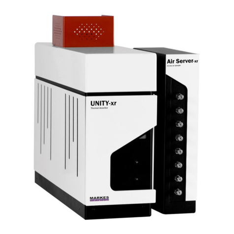
Markes International UNITY-Air Server-xr User manual

Markes International
Markes International BioVOC-2 User manual

Markes International
Markes International Unity 2 User manual

Markes International
Markes International HiSorb Agitator U-HSAG-20 User manual

Markes International
Markes International Easy-VOC User manual

Markes International
Markes International ACTI-VOC C-LFP-01 User manual