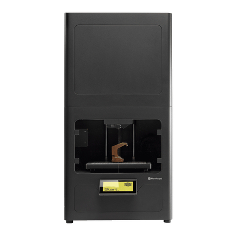
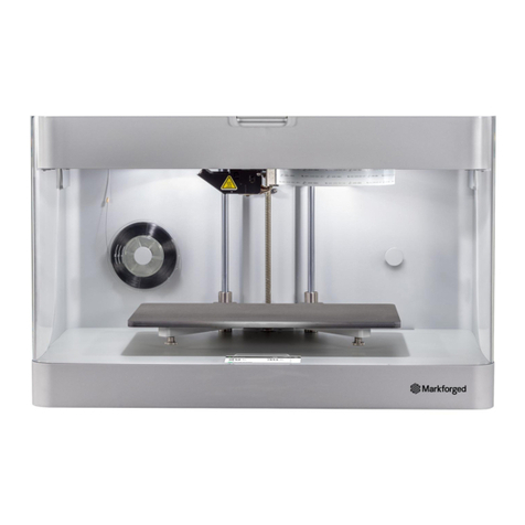
Markforged MARK TWO User manual

1
DESKTOP PRINTER SERVICE MANUAL
DESKTOP PRINTER
SERVICE MANUAL

DESKTOP PRINTER SERVICE MANUAL
2
Markforged
480 Pleasant St
Watertown MA 02472
USA
https://support.markforged.com
suppor[email protected]
For the latest PDF version of this document, visit our
support website.
Copyright © 2019 Markforged, Inc. All rights reserved.
Changes are periodically made to the information herein
which will be incorporated in revised editions of this
publication.
Markforged may make changes or improvements to
the product(s) described in this publication at any time
and without notice.
Version 1.2 / January 2020

3
DESKTOP PRINTER SERVICE MANUAL
TABLE OF CONTENTS
SERVICE NOTES 4
CHECKING ELECTRONICS CONNECTIONS 6
VERIFY CONNECTIONS TO BEAGLEBONE AND MOTHERBOARD
VERIFY USB CONNECTIONS
REPLACING THE FIBER EXTRUDER 9
REPLACING THE PLASTIC EXTRUDER 11
A1095 EXTRUDER REPLACEMENT
A3648 EXTRUDER REPLACEMENT
REPLACING THE XY STEPPER MOTORS 20
REPLACING THE PRINT HEAD 22
REPLACING THE MOTHERBOARD 27
REPLACING THE PRINT VISOR 31
REPLACING THE TENSIONER ASSEMBLY 33
REPLACING THE TOUCHSCREEN 37
REPLACING THE BEAGLEBONE 41
REPLACING THE RIBBON CABLE 46
REPLACING THE Z-AXIS LEAD SCREW 54
DISABLING THE WI-FI ADAPTER 57

DESKTOP PRINTER SERVICE MANUAL
4
SERVICE NOTES
QUALIFIED SERVICE PERSONNEL
Markforged products contain high voltage and other hazards. Do not remove any panels or protective guards
without appropriate technical training and experience necessary to minimize the risks to yourself and others. If
you do not feel comfortable accessing service areas of your Markforged product, please contact your VAR.
FUSE LOCATIONS
LOCATION MFG VOLTS AMPS SPEED
Power entry module Bel Fuse 5ET5-R 250VAC 5A Time delay
Note: Only the specified fuses may be used as replacements. Third-party substitutes are not
permitted.
NOTE ON FIBER CAPABILITY
This Service Manual covers all models of Markforged Desktop Series printers. If your printer model is not
Service Manual may not apply. Such sections will be marked with
the icon to the left.
A1095 AND A3648 EXTRUDERS
The photos in the User Guide and Service Manual depict both the original A1095 (below left) and the updated
A3648 extruders (below right). All Gen 2 printers come equipped with the A3648 extruder and all Gen 1 printers
come equipped with the A1095 extruder (see Note on Hardware Differences
procedures are noted in the text.
SERVICE MANUAL

5
DESKTOP PRINTER SERVICE MANUAL
NOTE ON HARDWARE DIFFERENCES
PRESERVING FACTORY CALIBRATION

DESKTOP PRINTER SERVICE MANUAL
6
CHECKING ELECTRONICS CONNECTIONS
QService Notes (p.4).
Note: Take care not to discard any hardware you remove during this procedure, as you may need it
during the reinstallation.
PREPARE YOUR PRINTER FOR INSPECTION
secure. Before you can start checking connections, your printer must be properly prepared.
1. Unload all print material.
2.
3.
4. Disconnect the feed tube from the plastic extruder. Remove it from the printer and set it aside.
5.
6. Tape the lid and visor of the printer closed to prevent them from accidentally opening.
7. Carefully turn the printer upside down so that the bottom is facing up.
8. Remove and set aside the 10 screws that hold the bottom panel in place.
Note: The color of the metal BeagleBone cover may vary; the boards themselves are identical.
9. Remove and set aside the bottom panel.
VERIFY CONNECTIONS TO BEAGLEBONE AND MOTHERBOARD
1. Disconnect all of the cables on the left and right sides of the BeagleBone with the exception of the
grey cable. Disconnect the grey cable from the green motherboard but leave it connected to the
BeagleBone.
2. Pull up on the BeagleBone case to remove it from the touchscreen. Note that this connection is very high
Note: You should be left with only the touchscreen attached to the printer frame.
3. Turn the BeagleBone over and inspect the connection between the grey wire and the BeagleBone. Ensure
that it is properly secured.
4. If the grey wire is connected properly, replace the BeagleBone back on the board and secure it to the
prongs on the touchscreen.
Note: Ensure that the USB port on the BeagleBone faces toward the USB hub.
5. Reattach all of the cables to the BeagleBone including the grey wire to the motherboard. Verify that all
motherboard connections are tight and secure.

7
DESKTOP PRINTER SERVICE MANUAL
CHECKING ELECTRONICS CONNECTIONS
QService Notes (p.4).
Note: Take care not to discard any hardware you remove during this procedure, as you may need it
during the reinstallation.
PREPARE YOUR PRINTER FOR INSPECTION
secure. Before you can start checking connections, your printer must be properly prepared.
1. Unload all print material.
2.
3.
4. Disconnect the feed tube from the plastic extruder. Remove it from the printer and set it aside.
5.
6. Tape the lid and visor of the printer closed to prevent them from accidentally opening.
7. Carefully turn the printer upside down so that the bottom is facing up.
8. Remove and set aside the 10 screws that hold the bottom panel in place.
Note: The color of the metal BeagleBone cover may vary; the boards themselves are identical.
9. Remove and set aside the bottom panel.
VERIFY CONNECTIONS TO BEAGLEBONE AND MOTHERBOARD
1. Disconnect all of the cables on the left and right sides of the BeagleBone with the exception of the
grey cable. Disconnect the grey cable from the green motherboard but leave it connected to the
BeagleBone.
2. Pull up on the BeagleBone case to remove it from the touchscreen. Note that this connection is very high
Note: You should be left with only the touchscreen attached to the printer frame.
3. Turn the BeagleBone over and inspect the connection between the grey wire and the BeagleBone. Ensure
that it is properly secured.
4. If the grey wire is connected properly, replace the BeagleBone back on the board and secure it to the
prongs on the touchscreen.
Note: Ensure that the USB port on the BeagleBone faces toward the USB hub.
5. Reattach all of the cables to the BeagleBone including the grey wire to the motherboard. Verify that all
motherboard connections are tight and secure.

DESKTOP PRINTER SERVICE MANUAL
8
VERIFY USB CONNECTIONS
1. Verify that the connection from the USB hub to the BeagleBone is secure.
2. Verify that the connection from the bottom of the USB hub is secure.
3. If there is a connection between the USB hub and the motherboard, verify that it is secure at both ends.
4. If there is a USB cable attached to the motherboard, verify that it is secure at both ends.
CLEANUP
1. Replace the panel and reinstall all 10 screws.
2. Carefully turn the printer upright.
3. Remove and discard the tape holding the lid and visor shut.
4. Reinstall the print bed.
5.
6. Reconnect the plastic feed tube to the plastic extruder.
7. Plug in and power up the printer.
8. Load print material.

9
DESKTOP PRINTER SERVICE MANUAL
REPLACING THE FIBER EXTRUDER
Note: Take care not to discard any hardware you remove during this procedure, as you will need it
during the reinstallation.
Tools
●Wire cutters
●
●2mm hex key
●2.5mm hex key
FIBER EXTRUDER REMOVAL
1. Unloading Fiber in the User Guide.
2. Cool the print head (Menu > Utilities > Manual Control > Temperature Control > Cool).
Note: The print head may take several minutes to completely cool.
3.
4.
Note: Do not unscrew it all the way. It should require no more than one full turn to loosen.
5.
6.
Note: Do not unscrew it all the way. It should require no more than one full turn to loosen.
7.

DESKTOP PRINTER SERVICE MANUAL
10
8.
Note: The bracket on the extruder has keyhole slots that enable the extruder to slide out without
the screws being removed.
9.
10.
Note: You may need to use pliers to remove the 4-wire connector. Be careful not to let the base
of the extruder sever the wires.
11.
FIBER EXTRUDER REPLACEMENT
1.
ensure that they are plugged in all the way.
2.
align with the screws.
3. Tighten the four screws that connect the base of the extruder to the chassis.
4.
5.
6. Power on your printer.
7. Loading Fiber in
the User Guide.

11
DESKTOP PRINTER SERVICE MANUAL
REPLACING THE PLASTIC EXTRUDER
Note: Take care not to discard any hardware you remove during this procedure, as you will need it
during the reinstallation.
The procedure for replacing a plastic extruder depends on the model of the extruder currently installed in your
printer. See the image below to determine which procedure applies to you, then follow the instructions in the
corresponding subsection to replace your plastic extruder.
Tools
●2mm hex key
●2.5mm hex key
A1095 EXTRUDER REPLACEMENT
Remove A1095 extruder
1. Completely unload all print materials. For more information, see Unloading Plastic and Unloading Fiber,
if applicable, in the User Guide.
2. Cool the print head (Menu > Utilities > Manual Control > Temperature Control > Cool).
Note: The print head may take several minutes to completely cool.
3.

DESKTOP PRINTER SERVICE MANUAL
12
4.
Note: Do not unscrew it all the way. It should require no more than one full turn to loosen.
5.
channel at the bottom of the plastic extruder toward the back of the printer.
6. Unscrew the thumbscrew that connects the plastic Bowden tube to the plastic extruder.
7. Remove the plastic Bowden tube from the plastic extruder and let it hang freely.
8.
Let it hang freely.
9. Using the 2.5mm hex key, fully remove the two screws that attach the plastic extruder bracket to the
printer casing and set them aside.

13
DESKTOP PRINTER SERVICE MANUAL
10. Unclip the white wire clip that connects wires between the plastic extruder and the printer.
11. Remove the plastic extruder from the printer. Take care not to remove the supporting bracket.
Replace A1095 extruder
1. Place the new plastic extruder in the bracket on the printer chassis where the old extruder sat.
2.
3. Place the screws and lock washers from the old extruder into the holes on the bracket and tighten them
4.
the printer.
5.
6.
thumbscrew.
7. Reinstall the plastic feed tube to the rear of the plastic extruder.
8. Power on the printer and reload materials. For more information, see Loading Plastic and Loading Fiber,
if applicable, in the User Guide.

DESKTOP PRINTER SERVICE MANUAL
14
A3648 EXTRUDER REPLACEMENT
Remove A3648 extruder
1. Completely unload print material. For more information, see Unloading Plastic and Unloading Fiber, if
applicable, in the User Guide.
2. Cool the print head (Menu > Utilities > Manual Control > Temperature Control > Cool).
Note: The print head may take several minutes to completely cool.
3.
4.
5.

15
DESKTOP PRINTER SERVICE MANUAL
6.
printer.
7. Unscrew the thumbscrew connecting the plastic Bowden tube to the plastic extruder.
8.

DESKTOP PRINTER SERVICE MANUAL
16
9. Using the 2.5mm hex key, remove and set aside the two screws securing the extruder to the rail.
10.

17
DESKTOP PRINTER SERVICE MANUAL
11.
12. Remove the plastic extruder and set it aside.
Replace A3648 extruder
1.

DESKTOP PRINTER SERVICE MANUAL
18
2.
3. Install the extruder on the rail, pushing it back against the case until the mounting holes line up. Use the
2.5mm hex key to install the two screws, securing the extruder to the rail.
4. Connect the plastic feed tube to the plastic extruder.
5. Connect the plastic Bowden tube to the plastic extruder and tighten the thumbscrew.

19
DESKTOP PRINTER SERVICE MANUAL
6.
7.
8. Carefully tuck all internal cables and connectors below the lid of the printer.
9. Power on the printer.
10. Reload print material. For more information, see Loading Plastic and Loading Fiber, if applicable.

DESKTOP PRINTER SERVICE MANUAL
20
REPLACING THE XY STEPPER MOTORS
Your printer’s motion system operates via two stepper motors, one in each of the two leftmost corners of the
gantry. Perform the procedure below to replace one of these motors.
wires or other components in the printer during this process.
Note: Take care not to discard any hardware you remove during this procedure, as you will need it
during the reinstallation.
Tools
●2.5mm hex key
XY STEPPER MOTOR REMOVAL
1.
2. Using the 2.5mm hex key, remove the four screws from the underside of the printer case shelf that
connect it to the stepper motor, and carefully set them aside.
3. Lift the stepper motor up from the metal shim on which it sits.
4. Remove the belt from around the pulley of the stepper motor.
Table of contents
Other Markforged 3D Printer manuals