Markforged Metal X User manual

Pre-Install Guide_2.0.0 | September 11, 2018
CONFIDENTAL. DO NOT DUPLICATE OR REDISTRIBUTE
METAL X SYSTEM
MARKFORGED PRE-INSTALLATION GUIDE

CONFIDENTAL. DO NOT DUPLICATE OR REDISTRIBUTE
Pre-Install Guide_2.0.0 | September 11, 2018 2
OVERVIEW
This guide will assist with preliminary setup of your Markforged Metal X system.
When you have completed the steps in this guide, you will be ready to contact your
Markforged reseller (hereafter the “Installer”) to proceed with the bulk of the install
process.
This document assumes that you are familiar with the Metal X System Facilities
Guide and have met all facilities requirements.
You should review the Pre-Installation Checklist at the end of this document before
proceeding. The Installer will not carry out the full installation until the entire
checklist is complete.
Before receiving and uncrating your Metal X devices, you should consult with your
Markforged Installer and decide together whether you or the Installer will congure
your Metal X printer and print your initial test part. This document details the steps
necessary to prepare your site for the Installer and refers you to the Markforged
support website (support.markforged.com) for any additional steps.
You should retain all original packing materials for your Metal X system.
SPACE AND MATERIALS
You should clear a space at least 10’x10’ for uncrating each of your Metal X system
components, with a clear path from the uncrating area to the nal operating locations.
You will need a power drill, scissors, and an optional pry bar during the uncrating
process. We recommend that you take photos of your Metal X System devices before
removing them from their crates in order to document any damage that might have
occurred during shipping.

CONFIDENTAL. DO NOT DUPLICATE OR REDISTRIBUTE
Pre-Install Guide_2.0.0 | September 11, 2018 3 3
Note the pallet marking ‘FRONT.’ When you open the
crate, be mindful of the two doors on the front face
of the Metal X printer.
Once the shipping crate is safely placed in the uncrating
area and a clear path to the operating location is
available, begin to unpack the crate.
1. Unscrew and remove the top of the shipping crate.
Before you uncrate and transport your Metal X printer, you must comply with the
site requirements in the Metal X System Facilities Guide.
Exercise caution when moving the device; the printer weighs approximately 130lbs
and must be placed on an appropriate table, desk, or stand with appropriate clearance
on all four sides. (See the Facilities Guide for details.)
Before uncrating your Metal X printer, make sure you have a clear path from the
10’x10’ uncrating area to the install location. You will need a power drill (Phillips #2
bit) for uncrating and a knife or pair of scissors.
Always perform safe two-person lifts from the bottom of the device when moving
the Metal X printer.
Do not attempt to carry the device singlehanded.
METAL X

CONFIDENTAL. DO NOT DUPLICATE OR REDISTRIBUTE
4Pre-Install Guide_2.0.0 | September 11, 2018
Strips of foam are attached to all six faces of
the crate to secure the Metal X printer. There is no
need to detach them.
2. Unscrew all four
sides of the crate,
i n c l u d i n g t h e
securing block at the
bottom of the crate.
3. Lift out the four side walls to remove them from the
shipping crate and set them aside.
4. Remove the two clear plastic sheets covering the
printer. (This step requires two people.)
Do not yet remove the sheet of blue plastic
securing the print chamber door. The print chamber
contains the accessory kit, which should be removed
when the printer reaches its permanent location.
For your safety and to avoid damaging the printer, do not leave the Metal X
unattended with the crate disassembled and securing block removed.
METAL X
4

CONFIDENTAL. DO NOT DUPLICATE OR REDISTRIBUTE
5Pre-Install Guide_2.0.0 | September 11, 2018
METAL X
MOVING THE METAL X
An elevator is required to transport the Metal X between oors.
While lifting, be mindful of the upper (opaque) access panel. If it swings open as
you move the printer, you can repurpose some of the leftover blue tape to secure
it temporarily.
1. Use safe lifting techniques to remove the Metal X
printer from its crate. The printer weighs approximately
130lbs and is slightly top-heavy; we recommend that
two people lift the printer from the bottom while a
third steadies it near the middle.
The printer is solid across its bottom face, with no ridges
or protrusions. You should not need work gloves to lift
it. Be mindful of the bottom block in the crate -- lift the
printer straight up to avoid nger injury.
2. Set the Metal X up on an appropriate table, stand, or
bench with the necessary clearance on all sides. (See
the Facilities Guide for details.)
3.
door and discard it.

CONFIDENTAL. DO NOT DUPLICATE OR REDISTRIBUTE
6Pre-Install Guide_2.0.0 | September 11, 2018
4. Remove the three pieces of shipping foam from the
print chamber.
5. Remove the accessory kit from the print chamber
and set it aside.
6. Open the upper chamber door to access the print
head. Cut, remove, and discard the zip tie securing
the print head; take care not to scratch or otherwise
damage the print head when doing so.
The Metal X printer ships with both its metal and
release material nozzles installed.
STOP HERE.
At this point you have completed the mandatory Metal X Printer pre-install procedure.
If you have made arrangements with your Installer to complete the printer installation
and conguration yourself, proceed to page 7; otherwise you may proceed to the
Wash-1 pre-install procedure on page 8.
METAL X

CONFIDENTAL. DO NOT DUPLICATE OR REDISTRIBUTE
7Pre-Install Guide_2.0.0 | September 11, 2018
METAL X
OPTIONAL INSTALLATION STEPS
If you do complete the Metal X Printer installation yourself, you will need to carry
out the following steps. Those marked with an asterisk (*) are documented on our
support site, https://support.markforged.com; refer to the site for further instructions.
1. Connect the included power cord to the Metal X and plug it into its dedicated wall
outlet.
2. Install the included Wi-Fi antenna and/or Ethernet connection.* See the Facilities
Guide
3. Power up the Metal X unit.
4.
5. Set up your Markforged software account and Eiger organization* at https://eiger.io
6. Register your printer online,* then power cycle the printer.
7. When you power up the Metal X printer, the upper chamber will automatically heat.
This entire process can take up to an hour.*
8. Perform the Bed Level utility. This will take several minutes.*
9. Insert a new print sheet and establish a vacuum seal.*
10. Mount spools of metal and release material in the upper chamber. Visually inspect
the material to make sure there are no breaks or tangling.
11. Load metal material into the print head.*
12. Load release material into the print head.*
13.
14. Print a test part on the Metal X printer.*

CONFIDENTAL. DO NOT DUPLICATE OR REDISTRIBUTE
Pre-Install Guide_2.0.0 | September 11, 2018 8
Before you uncrate and transport your Wash-1 part washer, you must comply with
the site requirements in the Metal X System Facilities Guide.
You must have a supply of Opteon SF79 on site before the Installer arrives. The
Wash-1’s uid capacity is 8.5 gallons; we recommend that you purchase three
45lb (5 gallon) pails to cover the initial ll of the device with sucient extra solvent
remaining. Your Reseller may be able to source Opteon SF79 for you.
To ll your Wash-1 with solvent you will also need a drum wrench (McMaster #
6512A12 or equivalent), which must be purchased separately; it is not provided with
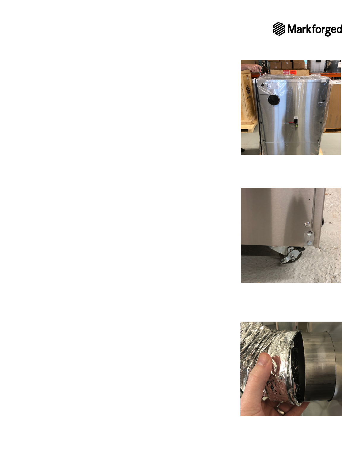
the Wash-1 unit itself. You will also need to provide 4” exible ducting to connect
the Wash-1 to your facility exhaust.
The Wash-1 is much heavier than the Metal X (approximately 300lbs) but sits directly
on the oor during operation and can be rolled to its permanent location once
removed from its shipping crate.
You should allocate space for separately storing clearly marked green (newly
printed) and brown (washed) parts, which are not easily distinguished by sight. If
you are uncertain about whether a part has been washed, then in order to avoid
clogging your Sinter-1, assume that the part is unwashed.
SPACE AND MATERIALS
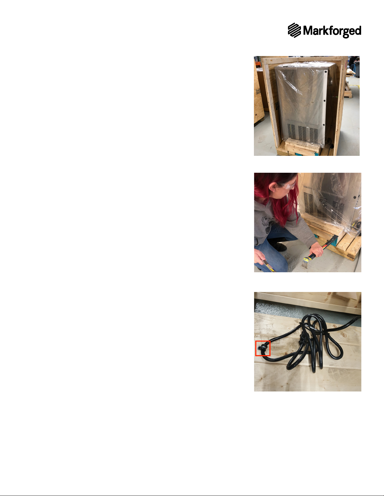
Use of a pry bar and power drill for uncrating is optional.
Before uncrating your Wash-1, clear a 10’x10’ uncrating area with an unobstructed
path to its nal location. Due to the size and weight of the Wash-1, transporting it
between oors requires an elevator.
Make sure the Wash-1’s wheel locks are engaged once it reaches its operating
location and any time it’s left unattended.

CONFIDENTAL. DO NOT DUPLICATE OR REDISTRIBUTE
9Pre-Install Guide_2.0.0 | September 11, 2018 9Pre-Install Guide_2.0.0 | September 11, 2018
1. Place the Wash-1 crate at the center of a 10’x10’
uncrating area to allow full freedom of movement.
2. Unscrew and remove the top and side walls from the
shipping crate.
3. Use a pry bar to remove the wood block securing the
lower portion of the Wash-1 unit. This will enable you
to slide the Wash-1 forward and tip it carefully out of
the crate.
4. Cut the plastic straps securing the Wash-1 to the pallet.
5. Unscrew the plastic/metal tie securing the power cord
to the bottom of the crate, and discard.

CONFIDENTAL. DO NOT DUPLICATE OR REDISTRIBUTE
Pre-Install Guide_2.0.0 | September 11, 2018
6. Remove the plastic covering from the Wash-1 unit.
7. Using safe lifting technique, remove the Wash-1 from
Be mindful of the water drain, which protrudes 4”
from the rear face of the unit. There is also a bolt protruding
1” from the bottom of the Wash-1; be aware of it when
sliding the unit forward out of the crate. Removing the
Wash-1 from its crate should take 2-3 people.
8. Roll the Wash-1 to its final operating location with
screen facing outward and water drain in rear, near
its facility exhaust connection. Use an elevator when
9. Engage the wheel locks when the Wash-1 is in its
operating location, or when leaving it unattended.
10. Remove the accessories and documentation from
inside the unit and set aside for the Installer.
Store the Wash-1 packing crate and materials.
Note: Ensure that all documentation is removed from
inside the unit before connecting exhaust. Failure to
do so may result in documentation being ingested into
your facility exhaust.
1. Connect your facility exhaust to the 4” round duct on the
rear of the Wash-1 station and secure the connection
appropriately.

CONFIDENTAL. DO NOT DUPLICATE OR REDISTRIBUTE
Pre-Install Guide_2.0.0 | September 11, 2018
Due to its exhaust, power, and gas supply requirements, the Sinter-1 requires the
most complex facilities planning and installation of the Metal X system. However,
the pre-installation steps for the device itself are straightforward.
Before you uncrate and transport your Sinter-1 furnace, you must fully comply with
the site requirements and procedures in the Metal X System Facilities Guide.
SPACE AND MATERIALS
The Sinter-1 shipping crate contains a large number of boxes;
all but one are simply set aside for the Installer. You are responsible for moving the
Sinter-1 furnace to its operating location and installing the gas supply panel, but
every other item in the shipping crate is for the Installer.
Take special note of the 60lb Kanthal furnace tube, which is secured in a foam
cradle beneath the furnace. The entire pallet, with the tube inside, must be laid at
in a secure location to await nal installation. Be sure to allocate space to store the
pallet and tube when planning the pre-install procedure. Use safe lifting techniques
when moving the pallet.
Along with space to store the tube/pallet and the remaining boxes, you must prepare
a 10’x10’ uncrating area with a clear path to the operating location. You will need a
power drill (Phillips #2 bit) and 9/16” socket wrench to uncrate the device.
A forklift is recommended for moving the Sinter-1 from crate to operating site, using
lifting straps to secure the unit; alternatively, it can be carefully transported by 2-3
people using safe lifting techniques. It weighs approximately 200lbs. Do not attempt
to carry the Sinter-1 singlehanded.
Always wear work gloves when lifting the Sinter-1; the bottom of the device has
rough edges.
When the requirements in the Facilities Guide are met and uncrating and storage
areas are available, you are ready to uncrate your Sinter-1.

CONFIDENTAL. DO NOT DUPLICATE OR REDISTRIBUTE
Pre-Install Guide_2.0.0 | September 11, 2018
required for this pre-install procedure are the furnace itself and the gas
panel; everything else is set aside for the Installer, including the tube securely
contained in its cradle.
1. Unscrew and remove the top of the shipping crate. Preserve the original shipping
crate and materials. Remove all boxes from the shelf (including two empty boxes),
and set them safely aside.
2. Unscrew the front wall of the crate. Lift the front wall out to remove it from the crate,
and set it aside. Note that the rear of the Sinter-1 faces the front of the crate.
3. After removing the front crate wall, remove box 9 (bakeout ducts) and box 1 containing
the gas panel, both of which rest at the bottom of the
crate in front of the Sinter-1 (see image).
4. Slide the upper shelf out of the shipping crate and set
it aside. Remove boxes 5 and 6 from the cubby at the
bottom of the crate and set them aside for the Installer.
5. Now unscrew and lift out the rear crate wall. Then
remove the four securing bolts with a 9/16” socket
wrench (not included) and lift out the side walls. Set
the crate walls aside. You are now ready to move the
6. Safely transport the Sinter-1:
A. Utilize lifting straps
under the furnace and lift the device by the straps
B. Using safe
lifting technique, lift the device out of the crate
not use lifting straps. (This should take 2-3 people.)

CONFIDENTAL. DO NOT DUPLICATE OR REDISTRIBUTE
Pre-Install Guide_2.0.0 | September 11, 2018
STORING THE FURNACE TUBE
The furnace tube remains secure in its padded cradle atop the pallet, beneath
the furnace. Do not attempt to lift the pallet and tube singlehanded. Carefully
transport the pallet, with the tube secure inside, to its storage space for the
Installer. Do not remove the tube from its cradle.
GAS SUPPLY PANEL INSTALLATION
You are responsible for installing the included gas supply panel along with a
Facilities Guide. For the
cylinder storage rack, we suggest
or equivalent. Once the rack is properly installed and
a single gas cylinder in place for reference, you can
mount the gas supply panel above it, within 3.6m
(12’) horizontal travel of the furnace, according to the
Facilities Guide
panel weighs more than 40lbs; exercise caution when
lifting and mounting it.
A mounting bracket is included in the gas supply panel
above the gas supply cylinder rack, and the supply
panel suspended from it.
1. Before mounting the panel, determine its location
relative to the cylinder rack. Mark the four bolt-hole
locations on the wall -- a two-person task. Then remove
the sheet metal panel cover and set the panel aside.
(See diagram on next page.)
2. To correctly situate the bracket on the wall, draw a
straight line between the upper two markings; the
bolt holes in the bracket will lie along this line. Center
the bracket along the line and securely fasten it to the
wall using appropriate hardware.
3. Lower gas supply panel into place, suspended from
the bracket, flush with the wall. Securely fasten to
the wall using appropriate hardware. Set aside any
remaining shipping material.

CONFIDENTAL. DO NOT DUPLICATE OR REDISTRIBUTE
Pre-Install Guide_2.0.0 | September 11, 2018
2X
304.8
12
2X
812.8
32
609.6
24
3X
203.2
8
ALL 6 UPPER
MOUNTING HOLES
ARE IN-LINE
HORIZONTALLY
SUPPLY PANEL CAN SLIDE 2 INCHES EACH DIRECTION ON
THE WALL BRACKET TO ALLOW EASIER ALIGNMENT OF
PANEL MOUNTING HOLES WITH WALL STUDS
Gas
Supply
Panel
(rear view)

CONFIDENTAL. DO NOT DUPLICATE OR REDISTRIBUTE
Pre-Install Guide_2.0.0 | September 11, 2018
ELECTRICAL SETUP
Before the Installer can complete the Sinter-1
installation, you must work with a licensed
electrician to connect the dedicated power
supply to the Sinter-1 unit. The facility electrical
supply should already meet the specications
in the Facilities Guide.
1. Remove the panel on the inlet (left-hand)
side of the unit.
2. After feeding through the conduit entry, line
1 connects to the left grey terminal block,
line 2/Neutral to the right grey terminal
block, and ground to the green/yellow
EQUIPMENT GROUNDING TERMINAL
Copper conductors only. 10AWG - 4AWG
5.5mm at head screwdriver
torque to 1.4 N-m (12 in-lb)
PHASE CONDUCTOR TERMINAL
Copper conductors only. 6AWG - 2AWG
4mm Allen hex drive
torque to 5.1 N-m (45 in-lb)
STOP HERE.
At this point you should contact your Installer to schedule the complete system
installation. If you have completed all the steps in this guide, you have fullled your
pre-installation responsibilities. The Installer will use the checklist on the following
pages to determine whether your site fully complies with all facility requirements
and is prepared for nal system installation, conguration, and setup.

CONFIDENTAL. DO NOT DUPLICATE OR REDISTRIBUTE
Pre-Install Guide_2.0.0 | September 11, 2018
METAL X
Uncrate and move printer to nal location
Installation location is environmentally controlled for temperature and humidity
Appropriate table / desk / stand for printer
Dedicated circuit at the printer location (see Facilities Guide for specications)
Compatible Wi-Fi or Ethernet network connection
Metal and release material on hand
▷Material is stored vertically or in original packaging and in a cool location
Print sheets on hand
Uncrate and move wash to nal location
Installation location is environmentally controlled for temperature and humidity
No excessive air movement (fans, blowers, open doors, etc.) at wash location
Wash-1 location has adequate space to meet clearance requirements
Wash-1 location can support the fully loaded weight of wash station
Wash location is not excessively unlevel
Dedicated circuit at the wash location (see Facilities Guide for specications)
4” round exhaust connected to Wash-1
▷Measure exhaust and conrm it is at least 100CFM. Record CFM: ________
15gal. of Opteon SF79 on hand
Drum wrench on hand
0.01g resolution scale on hand

CONFIDENTAL. DO NOT DUPLICATE OR REDISTRIBUTE
Pre-Install Guide_2.0.0 | September 11, 2018
Installation location is environmentally controlled for temperature and humidity
Move furnace from crate to permanent location / table
Appropriate table for furnace
Furnace location has adequate space to meet clearance requirements
▷Location accommodates space to install tube
▷Location accommodates space to install gas lines
Furnace location can support the fully loaded weight of the furnace
Furnace location is level
Compatible Wi-Fi or Ethernet network connection
Dedicated circuit for furnace (see Facilities Guide
▷Furnace permanently wired into circuit
4” or 6” round exhaust hookup at furnace loc`ation
▷Measure exhaust and conrm it is at least 100CFM. Record CFM: ________
Gas supply panel installed
Gas cylinder mounting rack installed
Gas cylinders on site
▷(2) 300cf of mix gas (97.1% Ar, 2.9% H2, UHP [99.999%])
▷(1) 300cf of backup inert gas (100% Ar, UHP [99.999%])
▷ (1) 230L medium/high pressure cryogenic liquid container of inert gas (100% Ar,
UHP [99.999%]
Other manuals for Metal X
2
Table of contents
Other Markforged 3D Printer manuals