Markforged Metal X User manual

MetalX_Facilities_Guide_2.4 | June 25, 2020
METAL X SYSTEM
FACILITIES GUIDE

Markforged
480 Pleasant St
Watertown MA 02472
USA
https://support.markforged.com
suppor[email protected]
Changes are periodically made to the information herein
which will be incorporated in revised editions of this
publication. For the latest PDF version of this document,
contact your Reseller. Make sure you have the most up-
to-date version.
Copyright © 2019 Markforged, Inc. All rights reserved.
Markforged may make changes or improvements to the
product(s) described in this publication at any time and
without notice.
This document is valid for all regions of the world; there is
no separate international version of the Facilities Guide.
Version 2.4 / June 2020

MetalX_Facilities_Guide_2.4 | June 25, 2020 3
OVERVIEW 5
SYSTEM COMPOSITION 5
FACILITIES PREPARATION 5
WASTE DISPOSAL 5
ELECTRICAL ACCESS 6
VENTILATION AND AIRFLOW 6
TECHNICAL SUPPORT 6
INSTALLATION SCHEDULE 6
SOFTWARE 7
MARKFORGED SOFTWARE INTEGRATION 7
SOFTWARE UPDATES 7
NETWORK REQUIREMENTS 7
METAL X 9
ELECTRICAL REQUIREMENTS 9
INCLUDED PLUGS 10
ENVIRONMENTAL REQUIREMENTS 11
CLIMATE CONTROL 11
VENTILATION REQUIREMENTS 11
MATERIAL STORAGE 11
INSTALLATION PLANNING 12
OPERATIONAL SPACE PLANNING 13
ACCESS REQUIREMENTS 13
ELECTRICAL REQUIREMENTS 15
ENVIRONMENTAL REQUIREMENTS 16
CLIMATE CONTROL 16
VENTILATION REQUIREMENTS 16
SOLVENT STORAGE 16
INSTALLATION PLANNING 17
SHIPPING AND UNLOADING 17
MOVING INFORMATION 17
OPERATIONAL SPACE PLANNING 18
ACCESS REQUIREMENTS 18
ADDITIONAL INFORMATION 19
NOTE ON CONNECTIVITY 19
LOCAL SOLVENT REGULATIONS 19
MACHINE CLEANING REQUIRED
EQUIPMENT 19
ADDITIONAL EQUIPMENT NEEDED 19
MARKFORGED FURNACES 20
ELECTRICAL SPECIFICATIONS 21
GROUND FAULT PROTECTION 22
OVERCURRENT PROTECTION 22
DEDICATED DISCONNECT 22
ENVIRONMENTAL REQUIREMENTS 23
CLIMATE CONTROL 23
VENTILATION REQUIREMENTS 23
REQUIRED FITTINGS 25
GAS CERTIFICATES 25
GAS SUPPLY PANEL MOUNTING
REQUIREMENTS 26
INSTALLATION PLANNING 27
SHIPPING AND UNLOADING 27
MOVING INFORMATION 27
OPERATIONAL SPACE PLANNING 28
ACCESS REQUIREMENTS 29
EMERGENCY PLANNING 30
METAL X SYSTEM FACILITIES GUIDE
TABLE OF CONTENTS

MetalX_Facilities_Guide_2.4 | June 25, 2020 4
ELECTRICAL SPECIFICATIONS 31
GROUND FAULT PROTECTION 32
OVERCURRENT PROTECTION 32
DEDICATED DISCONNECT 32
ENVIRONMENTAL REQUIREMENTS 33
CLIMATE CONTROL 33
VENTILATION REQUIREMENTS 33
REQUIRED FITTINGS 35
GAS CERTIFICATES 35
GAS SUPPLY PANEL MOUNTING
REQUIREMENTS 36
INSTALLATION PLANNING 37
SHIPPING AND UNLOADING 37
MOVING INFORMATION 37
MAINTENANCE SPACE PLANNING 38
MAINTENANCE ACCESS 38
OPERATIONAL SPACE PLANNING 39
FLOOR SPACE REQUIREMENTS 39
OPERATIONAL ACCESS 39
TABLE OF CONTENTS
METAL X SYSTEM FACILITIES GUIDE

MetalX_Facilities_Guide_2.4 | June 25, 2020 5
SYSTEM COMPOSITION
The Markforged Metal X System consists of three components: the Metal X printer,
the Wash-1 debinding station, and a Markforged furnace (Sinter-1 or Sinter-2). The
Metal X printer will arrive at your facility fully assembled and will require limited initial
setup. The Wash-1, Sinter-1, and Sinter-2 require additional facilities modication and
site preparation by authorized facilities maintenance sta and a certied electrician.
Specications (e.g. electrical and gas requirements) can vary from region to region;
consult your local suppliers and regulatory agencies for additional information. This
guide covers all regions. Markforged cannot provide support for devices installed
or operated outside of the specications in this guide.
FACILITIES PREPARATION
Facilities planning should be started as soon as possible after purchase to avoid
delaying the installation. This guide addresses the following planning considerations:
Modications to the installation area
Site accessibility
Planning the production area
Electrical and environmental requirements
Network connectivity
Environmental health and safety
All information in this guide assumes knowledge of the following:
Architectural and planning requirements
Applicable laws, regulations, and standards
Note that local health, safety, and access requirements take precedence over the
information presented in this guide. Consult local regulatory body with questions.
WASTE DISPOSAL
Material handling, storage, and disposal should be performed according to local
laws and regulations. See the Safety Data Sheets (SDS), if available, for storage
and handling information. Follow your Environmental Health and Safety regulations
where applicable, as well as supplier instructions.
METAL X SYSTEM FACILITIES GUIDE
OVERVIEW

6MetalX_Facilities_Guide_2.4 | June 25, 2020
ELECTRICAL ACCESS
The Metal X System installation must provide space for easy access to all electrical
disconnecting devices:
Power switch on rear face of Metal X printer
Power cable to Wash-1
Power switch on furnace (Sinter-1: rear panel, Sinter-2: front panel)
Facility power shuto for furnace
The Installer must be able to verify that dedicated branch circuits are available at the
operating locations for all Metal X System devices. Please coordinate with facilities
personnel at your site to conrm that each device is provided with a dedicated circuit.
In case of emergency, use the disconnecting devices to de-energize all Metal X
System units. Note that the Wash-1 has no dedicated disconnect or power switch;
de-energize Wash-1 by disconnecting plug from wall.
VENTILATION AND AIRFLOW
Metal X System devices should not be subjected to strong airow during operation
to avoid excessive and uneven cooling of parts. Do not set up the devices adjacent
to air vents, HVAC units, open windows, or other heat sinks or sources. See the
Ventilation Requirements sections for detailed facility exhaust specications.
TECHNICAL SUPPORT
For questions regarding installing, operating, and troubleshooting your Metal X System,
please contact your Reseller. They will coordinate with Markforged as necessary.
INSTALLATION SCHEDULE
We anticipate that installation will take approximately 5 days. If the site is set
up and supplied correctly prior to arrival and the Installer encounters no issues, it
will take a business week. However, issues such as incorrect facilities setup have
delayed past installs, causing them to extend into a second week. Some such delays
can be mitigated by customers providing early morning, late evening, and weekend
access to install sites.
Carefully read and follow all instructions in this document, and communicate early
and often with your Installer, to ensure a smooth and speedy installation.
METAL X SYSTEM FACILITIES GUIDE
OVERVIEW

MetalX_Facilities_Guide_2.4 | June 25, 2020 7
MARKFORGED SOFTWARE INTEGRATION
Markforged Eiger software can be accessed at https://www.eiger.io.
SOFTWARE UPDATES
In order to improve performance and oer additional system capabilities, software
and rmware updates are pushed regularly to all machines. Any machine that is
online will be automatically prompted to update whenever changes are available.
Updates should be performed at the earliest convenient time.
NETWORK REQUIREMENTS
Markforged devices communicate on the 2.4GHz Wi-Fi band. For assistance with
setting up your network, contact your internal IT team. Note that Markforged devices
do not support 5GHz Wi-Fi connections.
WIRED CONNECTIONS
Ethernet connections must utilize cables with a maximum length of 10 meters.
BROWSER
Markforged products require the use of Google Chrome. WebSockets must be
enabled.
INSTALLER NETWORK ACCESS
During initial installation, on-site online access must be provided to the Installer.
FIREWALL SETTINGS
Markforged devices support both DHCP and static IP congurations. For more
information, see the Advanced Networking Features article on the support site.
For proper operation, devices must be able to make outbound connections to
services at the following hostnames on the given ports (no inbound connections
are needed):
METAL X SYSTEM FACILITIES GUIDE
SOFTWARE

8MetalX_Facilities_Guide_2.4 | June 25, 2020
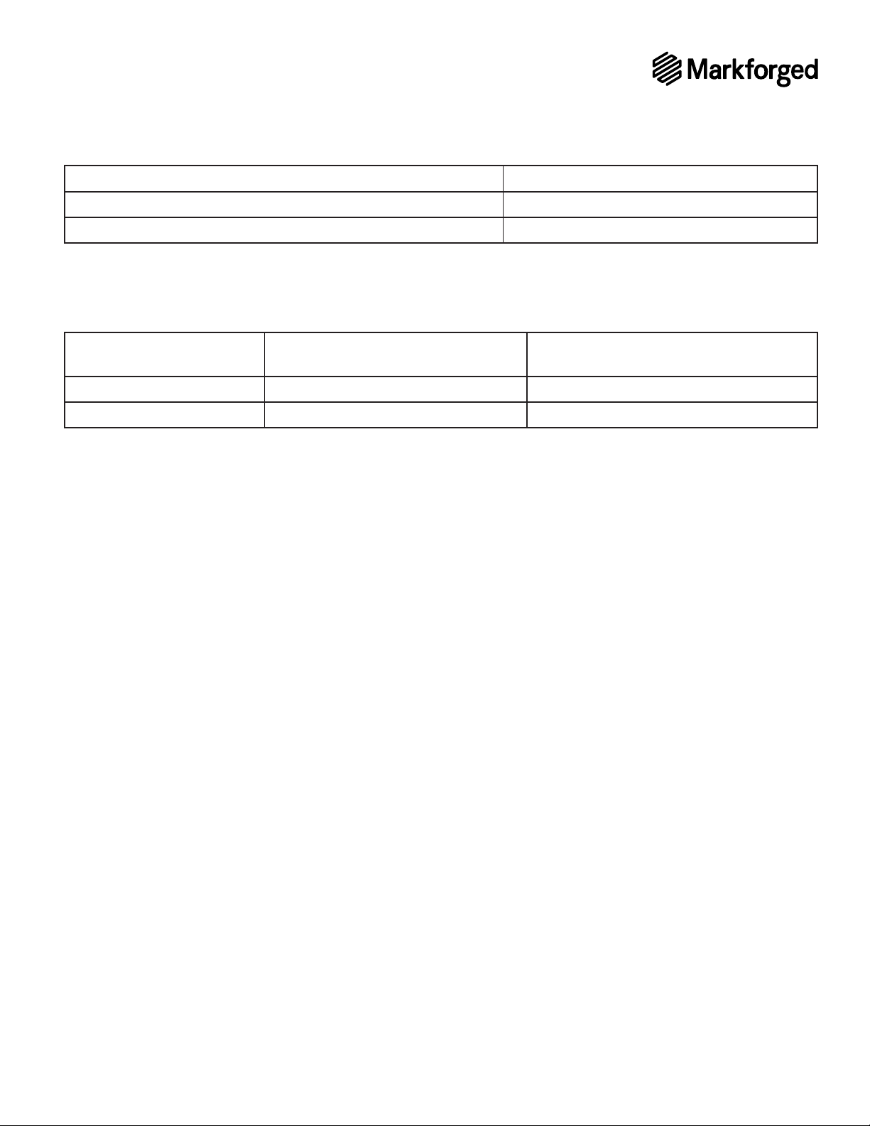
HOSTNAME PORT PROTOCOL REQUIRED? REASON
s3.amazonaws.com
mfeiger-production.
s3.amazonaws.com
TCP yes Downloading MFP part
cdn.eiger.io TCP yes Device operation
www.eiger.io TCP yes Connecting to Eiger (required to
view device status, queue print
*.pool.ntp.org 123 UDP yes Time synchronization via NTP is
required for devices to connect
80 TCP no Network connection status
check (primarily used for
data.logentries.com TCP no Remote logging of device events
and errors
data.logentries.com 10000 TCP no Legacy setting for remote
logging, only required if
software version is older than
Most of these services are cloud-based and geographically distributed, meaning
that the underlying IP address ranges are fairly broad and can change over time,
while the hostnames remain the same. This exibility allows Eiger to maintain a
higher level of availability and performance, and this mechanism is common for
many cloud-based applications you already use and trust.
DEVICE TIME SYNCHRONIZATION
Markforged products require accurate system time for securing HTTPS connections
to Eiger and other services; the SSL certicates used to ensure the authenticity
of these services have time-limited validity, and the device’s time must fall within
this window. Currently, NTP — Network Time Protocol, on UDP port 123 — is the
only supported mechanism for time synchronization, and Markforged devices will
attempt to connect to four dierent servers within the global public NTP server
pool, determined by querying hostnames ending in “.pool.ntp.org”.
Markforged devices also support customer-specied NTP servers. When a device
receives NTP server IP addresses via DHCP (using DHCP option 042), these addresses
will also be used for time synchronization (connecting to UDP port 123).
METAL X SYSTEM FACILITIES GUIDE
SOFTWARE

MetalX_Facilities_Guide_2.4 | June 25, 2020 9
ELECTRICAL REQUIREMENTS
Circuit Type
Wiring System Single phase with safety ground
Input Frequency 50 - 60 Hz
INPUT VOLTAGE RATED CONTINUOUS
OPERATING CURRENT
MINIMUM OVERCURRENT
PROTECTION RATING
100 -120 VAC 12 A 15 A
6 A 10 A
Please locate the appropriate voltage and current combination for your use case
based on availability and local regulations.
Note: The Metal X can accept a voltage input from 100-120VAC or 200-240VAC.
No additional equipment is required. It will automatically detect the input voltage
and respond appropriately.
METAL X SYSTEM FACILITIES GUIDE
METAL X

MetalX_Facilities_Guide_2.4 | June 25, 2020
INCLUDED PLUGS
COUNTRY INCLUDED PLUG
USA, Canada, Mexico, Costa Rica,
Philippines 5-15P
Germany, France, Spain, Sweden, Austria,
Turkey, Indonesia, Netherlands, Poland,
Portugal
CEE 7/7
UK, Hong Kong, Ireland, Malta, Vietnam,
Singapore
Australia, New Zealand AS/NZS 3112
Taiwan YP-12
South Korea KS C 8305
Israel -none-
Switzerland, Liechtenstein, Rwanda SEV-1011
Denmark, Guinea 107-2-D1
Italy, Chile CEI 23-50
South Africa 15A
India 15A IS 1293
China
Argentina -none-
Japan JIS C 8303 Class I
Thailand
Note: Customer may purchase additional 15-amp rated power cord to utilize
alternate receptacle. Power entry module: IEC 60320 Type C20.
This list is not exhaustive. It is regularly updated as Metal X System shipments increase.
METAL X SYSTEM FACILITIES GUIDE
METAL X

MetalX_Facilities_Guide_2.4 | June 25, 2020
ENVIRONMENTAL REQUIREMENTS
CLIMATE CONTROL
Intended Use
Room Temperature (Operation)
Humidity Requirement (Operation) 0% - 95%, non-condensing
Room Temperature (Idle)
Humidity Requirement (Idle) 0% - 95%, non-condensing
Altitude
Pollution Degree 2
VENTILATION REQUIREMENTS
The Metal X melts thermoplastics and emits thermoplastic odors during printing.
Ensure that the Metal X is used in a well-ventilated area. No dedicated exhaust
is required for the printer. Additional measures may be required based on local
regulations.
MATERIAL STORAGE
To avoid damaging material, always store spools in a vertical orientation with as little
slack in the spool as possible.
Keep spools under 40 degrees Celsius (104°F) for long-term storage.
Storage space should be free from dust and vapors if stored spools have been
removed from original packaging.
Avoid impacts and shock when storing or transporting material.
For more information, see the Metal Material Storage article on the support site.
METAL X SYSTEM FACILITIES GUIDE
METAL X

MetalX_Facilities_Guide_2.4 | June 25, 2020
INSTALLATION PLANNING
Crate Dimensions
Crate Weight
Minimum Door Width to Move in Crate
SHIPPING AND UNLOADING
Allow for an area of at least 3m x 3m
(10ft x 10ft) to uncrate the printer
Plan on having at least two people to
remove the printer from the crate
An elevator is required for moving the
printer between levels
A dolly or cart that can withstand the
printer’s weight should be used to
move the printer
MOVING INFORMATION
Moving the Metal X after installation is not recommended. If you need to move the
printer, ensure that all material is unloaded, then remove spools and spool holders. In
addition, manually check whether the wiping station is loose and tighten its screws
if necessary.
Always lift the Metal X from the bottom with at least two people.
The print bed must be leveled after the printer is moved (see User Guide for
instructions).
Metal X
Crate
Uncrating Area
3m (10ft)
3m (10ft)
METAL X SYSTEM FACILITIES GUIDE
METAL X

MetalX_Facilities_Guide_2.4 | June 25, 2020
OPERATIONAL SPACE PLANNING
Ensure that the new location of the Metal X meets all facility requirements, including
electrical and table requirements; additionally, ensure that the Metal X is placed on
the table with at least six inches of table space on all four sides of the printer.
Printer Dimensions
Printer Weight
Full Load Weight
ACCESS REQUIREMENTS
Connectivity Access (Wi-Fi, Ethernet)
USB Access
Maintenance Access
Note: Place printer within 3m (10ft) of a dedicated outlet to ensure that the cord
will reach.
Note that the dimensions in the diagram below account for the access requirements
listed above and the minimum dimensions of the Metal X table. General accessibility
to the front of the printer is assumed.
METAL X SYSTEM FACILITIES GUIDE
METAL X

MetalX_Facilities_Guide_2.4 | June 25, 2020
Place the printer on a table of 750mm – 900mm
(2.5ft – 3ft) in height for best access
Minimum table top dimensions are 0.73m x
0.68m (29in x 27in)
Ensure that the table can support 1.5x the full
load weight of the printer (75 kg / 165 lbs)
Place the Metal X on a stable surface and take
steps to dampen vibration, as excessive vibration
may degrade system performance
Table surface must be level
ADDITIONAL INFORMATION
REQUIRED CLEANING EQUIPMENT
A shop vacuum with a HEPA (high eciency particulate air) lter
METAL X SYSTEM FACILITIES GUIDE
METAL X

MetalX_Facilities_Guide_2.4 | June 25, 2020
ELECTRICAL REQUIREMENTS
Circuit Type
Wiring System Single phase with safety ground
Input Frequency 50–60 Hz
Input Voltage 110 –120 VAC
Rated Continuous Operating Current 11 A
Note: When necessary, the Wash-1 ships with a transformer appropriate to the install
region. Transformer supplier information is as follows:
Nominal Input Voltage Manufacturer P/N
100 VAC ACUPWR AJU-1800
110 –120 VAC ---
220– ACUPWR
Units sold in Korea ship with the following transformer:
Nominal Input Voltage Manufacturer P/N
220 VAC Hanil Industry Co HI-2000D
METAL X SYSTEM FACILITIES GUIDE

MetalX_Facilities_Guide_2.4 | June 25, 2020
ENVIRONMENTAL REQUIREMENTS
CLIMATE CONTROL
Intended Use Indoor use
Room Temperature (Operation)
Humidity Requirement (Operation) 0% –95%, non-condensing
Room Temperature (Idle)
Humidity Requirement (Idle) 0% –95%, non-condensing
Altitude
Pollution Degree 2
VENTILATION REQUIREMENTS
The Wash-1 requires facility exhaust provided through a 100mm (4in) diameter round
duct. Only metal exhaust tubing is permitted — plastic or plastic-lined exhaust lines
may be compromised by the exhaust vapors.
To minimize solvent evaporation, there should be no excessive air movement (fans,
blowers, open doors, etc.) at the Wash-1 operating location.
1.4 m3/min (50 CFM)
2.8 m3/min (100 CFM)
SOLVENT STORAGE
The only solvents approved for use in the Wash-1 are Opteon SF79 (formerly sold
as Opteon Sion), Opteon SF80, and Tergo Metal Cleaning Fluid.
Solvent must be stored and handled in accordance with its Safety Data Sheet.
In advance of initial system install, you must purchase three 45lb (20kg / 5.4 gallon)
pails of solvent, to cover the initial ll of the device with sucient extra solvent
remaining. The uid capacity of the Wash-1 is 8.5 gallons.
In advance of initial system install, you must also purchase a solvent-compatible
container for water drain. (Consult solvent data sheet for information.)
METAL X SYSTEM FACILITIES GUIDE

MetalX_Facilities_Guide_2.4 | June 25, 2020
INSTALLATION PLANNING
Crate Dimensions
Crate Weight
Minimum Door Width to Move in Crate
SHIPPING AND UNLOADING
Allow for an area of at least 3m x 3m
(10ft x 10ft) of space to uncrate the
Wash-1
Plan on having at least two people
remove the Wash-1 from the crate
An elevator is required for moving the
Wash-1 between levels
The Wash-1 has integrated wheels
which should be used when moving
the machine
MOVING INFORMATION
Transporting the Wash-1 away
from its operating location after
installation is not recommended. If
you need to transport the Wash-1,
please remove all parts and loose
components (such as the wash
basket and drying rack) and drain
uid from the machine. For more
information, see the Drain Procedure
article on the support site
Ensure that the wheels are unlocked and moving freely before trying to move
the Wash-1. Do not lift or carry the Wash-1 to a new location
Always lock wheels when the Wash-1 is not in transit
Ensure that the new location of the Wash-1 meets all facility requirements,
including electrical and ventilation requirements
Uncrating Area
3m (10ft)
3m (10ft)
Wash-1
Crate
METAL X SYSTEM FACILITIES GUIDE

MetalX_Facilities_Guide_2.4 | June 25, 2020
OPERATIONAL SPACE PLANNING
Full Load Weight
The Wash-1 should sit directly on the oor
Floor surface should be at, stable, and capable of supporting the fully loaded
weight of the Wash-1. We recommend a nonporous hard oor surface
ACCESS REQUIREMENTS
Operational Access
Maintenance Access
Place Wash-1 within 2m (6.5ft) of dedicated
outlet to ensure that the cord will reach
Place Wash-1 in a space that has a height
clearance of at least 1m (3ft) above
the top of the unit to ensure room to
remove and replace the basket
Note that the dimensions in this diagram
account for the access requirements listed
above, the drains on the rear face of the
Wash-1, and the dimensions of the Wash-1
unit itself. General accessibility to the front
of the Wash-1 is assumed.
Wash-1
Rear Access Space
1m
(36in)
92cm
(36in)
45cm
(18in)
45cm
(18in)
METAL X SYSTEM FACILITIES GUIDE

MetalX_Facilities_Guide_2.4 | June 25, 2020
ADDITIONAL INFORMATION
NOTE ON CONNECTIVITY
The Wash-1 is a static debinding unit that does not connect to the Internet. Unlike
other Metal X System devices, the Wash-1 does not need to be registered to Eiger
or receive rmware updates.
LOCAL SOLVENT REGULATIONS
Consult local regulations to determine which approved solvents are allowed in your
region. Always dispose of used solvent in accordance with local regulations.
MACHINE CLEANING REQUIRED EQUIPMENT
A catch container of adequate size and chemical resistance to your chosen solvent
is required to aid in the process of removing used solvent.
ADDITIONAL EQUIPMENT NEEDED
0.01g-resolution scale (recommended 2kg capacity)
Note: In some cases, a higher-capacity scale may be necessary.
Drum wrench (for opening solvent containers)
4in ducting (to attach Wash-1 to facility exhaust)
Should you wish to purchase your own additional siphon pump, see solvent datasheet
and consult your Reseller for information regarding material compatibility.
METAL X SYSTEM FACILITIES GUIDE

MetalX_Facilities_Guide_2.4 | June 25, 2020 20
The rest of this Facilities Guide consists of facilities planning information for the
Sinter-1 and Sinter-2. It is expected that you are planning to install one type of device
or the other in your facility as part of the Metal X System, not both at once. As such,
you are only responsible for the section pertaining to the furnace you plan to install.
Note that all purchasers of a Sinter-2, including those who have previously purchased
and/or installed a Sinter-1, should familiarize themselves with the entire Sinter-2
section. In particular, the subsections on electrical, access, network, and installation
requirements are substantially dierent from the corresponding sections in the
Sinter-1 section of this Guide.
If you plan to install the , continue on to the Sinter-1 section ().
If you plan to install the Sinter-2, continue on to the Sinter-2 section ().
MARKFORGED FURNACES
METAL X SYSTEM FACILITIES GUIDE
Other manuals for Metal X
2
Table of contents
Other Markforged 3D Printer manuals