manuals.online logo
Brands
  1. Home
  2. •
  3. Brands
  4. •
  5. Martin Universal Design
  6. •
  7. Educational Equipment
  8. •
  9. Martin Universal Design Weber Creation Station U-DS90W User manual

Martin Universal Design Weber Creation Station U-DS90W User manual

4444 Lawton Avenue, Detroit, MI 48208 USA Tel:(313)895-0700/Fax:(313)895-0709
Email: Custservmud@aol.com visit us at www.MartinUniversalDesign.com
NEW U-DS90W/U-DS90B Creation Station Assembly Instructions
IMPORTANT
If you have difficulty assembling your U-DS90W
Creation Station or need customer service
assistance. Please call:
Martin Universal Design, Inc.
Customer Service Hot Line at
1-313-895-0700.
If you need additional parts,
it is not necessary to contact your dealer,
our Customer Service Rep. will forward them
to you immediately.
Parts List
[A] - 24" x 40" Top
(1 piece)
[G] - Pencil Ledge
(1 piece)
[M] - Cross Support
End Cap (2 pieces)
[S] - Nuts
(4 pieces)
[B] - Upper Base End
(2 pieces)
[N] - Footbar Spacers
(2 pieces)
[T] - 6x65mm
(6 pieces)
[C] - Lower Base End
(2 pieces)
[H] - Drawer Supports
(4 pieces)
[D] - Foot Bar (1 piece)
[E] - Cross Support
(1 piece)
[F] - Top Support
(1 piece)
[I] - Tilt Mechanism
(2 pieces)
[J] - Top L-Bracket
(2 pieces)
[U] - Collars - includes
knob and bolt
(4 pieces)
[L] - Castors
(2 Locking & 2 non-locking)
[O] - 6 x55mm
(6 pieces)
[P] - 6 x 28mm
(8 pieces)
[V] - Washer
(4 pieces)
[R] - 4 x 12mm
(2 pieces)
Pg. 1
Additional Tool needed: Phiillips Screwdriver
[Q] - 5x14mm
[K] -
Rods
Drawer Supports
(4 pieces)
[X] - Wrench (1 piece)
[Z] - Drawers
(2 sets - these need
to be assembled)
Please see assembly
sheet for drawers.
[Y] - Wrench with hole
(1 piece)
[W] - Allen Wrench
(1 piece)
(8 pieces)
Revised AUGUST 09
4444 Lawton Avenue, Detroit, MI 48208 USA Tel:(313)895-0700/Fax:(313)895-0709
Email: Custservmud@aol.com visit us at www.MartinUniversalDesign.com
NEW U-DS90W/U-DS90B Creation Station
Assembly Instructions
STEP 1] Assembly Base of Table
L (locking castor)
Begin by taking the [2] Lower Base End units (part C) and
attach the foot bar (part D) to the lower Base End units
using a foot bar spacer (part N) between each end of foot
bar and base end unit. Secure with [2] 6x65mm bolts (part
O). Loosley fasten bolts with Allen Wrench to allow for further
assembly of next step . See FIG 1.
Attach Cross support (part E) to each Base End Unit (part C).
First, attach the Cross Support End Caps (part M) to each
end of Cross Support. Continue by securing cross support to
leg of base unit with [2] 6x65mm bolts (part T). Tighten with
Allen Wrench and go back to tighten down foot bar
assembly bolts (part O) . See FIG 1.
Complete Step 1 by inserting [2] locking castors (part L)
into the front of the base end. Complete by inserting the [2]
remaining non-locking castors into the rear of the base.
Tighten down with wrench (part V). See FIG 1.
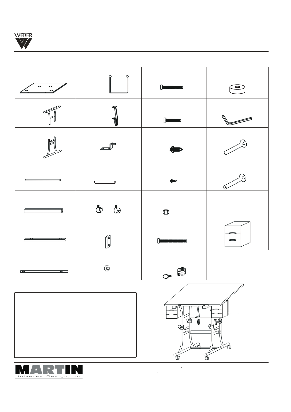
C
N
L
(non- locking castor)
O
T
T
O
M
E
N
FIG 1
STEP 2] Assembly Top portion of Base
Take each upper Base end (part B) attach to Top Surface
Cross Support (part F) using [2] 6x55mm bolts (part O).
Tighten and secure with Allen Wrench. See FIG 2.
FIG 2
STEP 3] Complete Base Assembly
Before combining the top portion to the bottom portion, slide
the collars (part K) onto each of the [4] ends of the lower
portion of the base. Tighten lower bolt found below knob on
collar. This secures collar to leg. Repeat with all 4 collars.
See FIG 3.
Once the collars are on the base, insert the top portion into
the lower portion of the base making sure the top ends slide
into the collars that are on the lower portion of the base.
Secure with the [4] male knobs into the collars and tighten.
See FIG 3.
NOTE: Knobs on collars are to secure table at desired
height.
FIG 3
O
B
F
O
U
B
Pg. 2
D
NOTE: Knobs should face inside Part CLower Base End.
Revised AUGUST 09
Assembly Instructions
STEP 4] Attaching Tilt Mechanism
Take the [2] Tilt Mechanisms (part I) and attach the one end
as show in FIG 4 to the Top Support (part F) using [2] 6x28mm
bolts (part P) and [2] nuts (part S) per tilt mechanism. Tighten
with wrench (part U) and Allen Wrench. Repeat with other
mechanism. See FIG 4.
FIG 4
FIG 4B
STEP 4B] Attaching Drawer Supports
After the previous steps, the Assembled Base should now
look like the picture shown at left if proper assembly was
completed.
Continue with assembly on next page.
I
S
P
H
Pg. 3
F
B
NEW U-DS90W/U-DS90B Creation Station
K
T
V
P
Revised AUGUST 09
Attach drawer support(part H) to drawer support rod
(part K) using(part P)6x28mm bolt.Continue by
attaching drawer support (part H) to upper
(part B) using ( part T) 6x65mm add ( part V)between
upper base end and ( part H) drawer support.Repeat
assembly with the remaining drawer supports.
SEE FIG 4B
base end
4444 Lawton Avenue, Detroit, MI 48208 USA Tel:(313)895-0700/Fax:(313)895-0709
Email: Custservmud@aol.com visit us at www.MartinUniversalDesign.com
NEW U-DS90W/U-DS90B Creation Station Assembly Instructions
Pg. 4
STEP 5] Attach Top to BaseFIG 5
NOTE: Use [2] people to help each other turn base over
onto Table Top.
Lay Table Top onto flat carpeted surface or empty flattened
carton insuring top wont scratch, making sure the T-nut holes
are facing up.
Now, place Base upside down onto top by lining up holes in
Tilt Mechanism (part I) with proper holes in top.
Note: The other [4] holes in top are for the L-Brackets .(part J)
Secure top to base using [2] each 5x14mm bolts (part Q) per
tilt mechanism (part I). Secure with Allen Wrench. Repeat
with other Tilt Mechanism.
Attach L-Brackets (part J) by inserting rod found on L-Bracket
into base, complete by attaching L-bracket to top using [2]
each 5x14mm bolts (part Q) per L-bracket. Secure with Allen
Wrench. Repeat with other side. See FIG 5.
I
Q
J
Q
STEP 6] Attachment of Pencil Edge
NOTE: Use [2] people to help each other turn base over
onto Castors.
Attach Pencil Edge (part G) to front edge of Top using [2]
each 4x12mm screws (part R). Tighten to secure. NOTE:
Keep screw slightly loose to allow for raising or lowering of
pencil edge. SEE FIG 6.
STEP 7] Drawer Assembly
See Drawer Assembly Instruction sheet for assembly.
Assemble Drawers (part Z) and then slide them into the
Drawer Supports (part H) found hanging on either side of
the table. Make sure the drawer fronts are facing the front
of the table. SEE FIG 7.
Once complete, double check all screws and bolts to make
sure they are secure.
Table is now ready for your enjoyment!
FIG 6
FIG 7
R
G
H
AJ
V
Z
Revised AUGUST 09
4444 Lawton Avenue, Detroit, MI 48208 USA Tel:(313)895-0700/Fax:(313)895-0709
Email: Custservmud@aol.com visit us at www.MartinUniversalDesign.com
NEW U-DS90W/U-DS90B Creation Station
Drawer Assembly Instructions
IMPORTANT
If you have difficulty assembling your U-DS90W Drawers or need customer service assistance.
Please call: Martin Universal Design, Inc. Customer Service Hot Line at 1-313-895-0700.
If you need additional parts, it is not necessary to contact your dealer,
our Customer Service Rep. will forward them to you immediately.
Drawer Parts & Quantity (makes 2 Drawer Banks)
Top - 2 Pieces Inside Section - 2 Pieces Drawers - 6 PiecesBottom - 2 Pieces
A B CD
A
D
C
B
After proper assembly
the drawers should look
like the above illustration.
Part W
WARNING: READ ALL INSTRUCTIONS FIRST BEFORE ASSEMBLING DRAWERS.
ONCE PIECES ARE SNAPPED TOGETHER THEY ARE SECURED.
Assemble your drawers by
taking the section [A] and
snapping into place -
by lining up the tabs with the
grooves in the outside edge
of section piece [B].
Complete by snapping
section [C] onto section A&B.
Finish by sliding the
[3] Drawers into the
drawer bank assembly.
Revised AUGUST 09

This manual suits for next models

1

Popular Educational Equipment manuals by other brands

3D Molecular Designs Enzymes in Action Kit Assembly instructions

3D Molecular Designs

3D Molecular Designs Enzymes in Action Kit Assembly instructions

Sensotec my Board Buddy GO manual

Sensotec

Sensotec my Board Buddy GO manual

ClassMate BOLTX501 user guide

ClassMate

ClassMate BOLTX501 user guide

LEXIBOOK EDU100i4 instruction manual

LEXIBOOK

LEXIBOOK EDU100i4 instruction manual

BenQ TDY31 user manual

BenQ

BenQ TDY31 user manual

PASCO SPARK user guide

PASCO

PASCO SPARK user guide

Rompa 21476 manual

Rompa

Rompa 21476 manual

Enabling Devices Switch & Glow user guide

Enabling Devices

Enabling Devices Switch & Glow user guide

CamJam EduKit 3 Assembly instructions

CamJam

CamJam EduKit 3 Assembly instructions

Nasco Healthcare Child CRiSis Starter Torso instruction manual

Nasco Healthcare

Nasco Healthcare Child CRiSis Starter Torso instruction manual

Talk To Me Technologies wego 13A-D quick reference

Talk To Me Technologies

Talk To Me Technologies wego 13A-D quick reference

Trainers for Trainers brain-train Q-wiz user guide

Trainers for Trainers

Trainers for Trainers brain-train Q-wiz user guide

OPEN DOOR DESIGN PPT MINI Assembly instructions

OPEN DOOR DESIGN

OPEN DOOR DESIGN PPT MINI Assembly instructions

Northern Avionics IES quick start guide

Northern Avionics

Northern Avionics IES quick start guide

Safe SC 808 user manual

Safe

Safe SC 808 user manual

RoboMaster S1 Education Expansion Set Core quick start guide

RoboMaster

RoboMaster S1 Education Expansion Set Core quick start guide

MakeKit hover:bit manual

MakeKit

MakeKit hover:bit manual

Rompa Cube Tube manual

Rompa

Rompa Cube Tube manual

manuals.online logo
manuals.online logoBrands
  • About & Mission
  • Contact us
  • Privacy Policy
  • Terms and Conditions

Copyright 2025 Manuals.Online. All Rights Reserved.