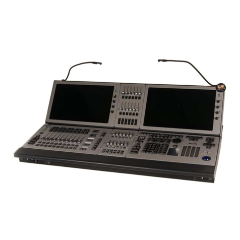
Martin Maxxyz User manual

Maxxyz
user manual
FOR USE WITH SOFTWARE VERSION 1.6

-All measurements are expressed in centimeters.
111
104
61
88
28 40
© 2003-2006 Martin Professional A/S, Denmark. All rights reserved. No part of this manual may be reproduced, in any form or by any
means, without permission in writing from Martin Professional A/S, Denmark. Printed in Denmark.
Information subject to change without notice. Martin Professional A/S and all affiliated companies disclaim liability for any injury,
damage, direct or indirect loss, consequential or economic loss or any other loss occasioned by the use of, inability to use or reliance
on the information contained in this manual.
P/N 35000115 Rev. D. May 2006

Table of Contents 3
T
ABLE
OF
C
ONTENTS
INTRODUCTION 9
MAXXYZ SAFETY INFORMATION 9
INCLUDED ITEMS 9
UNPACKING/PACKING THE CONSOLE 10
UNPACKING THE CONSOLE 10
PACKING THE CONSOLE 10
SETTING UPTHE CONSOLE 11
CONNECTING DMX DEVICES 11
CONNECTING THE DMX LINK 12
AC POWER 12
POWER SUPPLY 12
POWER CONNECTION 12
MAXXYZ LAYOUT AND DESCRIPTION 13
TYPES OF CONTROLS 14
THE PLAYBACK CONTROLS 15
THE PROGRAMMER CONTROLS 16
TRACKBALL CONTROL 17
SLIDER POTENTIOMETER (FADER) 18
GROUP MASTERS 18
OPERATOR AUDIO 18
DISPLAY SCREENS 19
DEFAULT PLAYBACK SCREENS 19
DEFAULT PROGRAMMER SCREENS 19
EDITING DISPLAY SCREENS 20
STARTING THE MAXXYZ 21
PATCHING FIXTURES 22
ADDING FIXTURES TO THE PATCH 22
THE FIXTURE LIBRARY 25
FIXTURE NUMBERING 27
ASSIGNING DMX ADDRESSES 28
PATCHING AN INDIVIDUAL FIXTURE 28
PATCHING ARANGE OF FIXTURES 29
PATCHING CONVENTIONAL DIMMERS 29
PATCHING ONE FIXTURE TO MULTIPLE DMX ADDRESSES 29
PATCHING MULTI-PART FIXTURES 30
OTHER PATCH FUNCTIONS 32
PATCHING SUMMARY 33
ADVANCED PATCHING SYNTAX 34
PATCHING THE “TRAINING 1.4 MAXXYZ” FILE 34
EDITING AN EXISTING PATCH 34
CLEARING AFIXTURE FROM PATCH 34
CLEARING DMX ADDRESSES 34
DELETING AFIXTURE FROM PATCH 35
MOVING AFIXTURE IN THE PATCH 36
COPYING AFIXTURE 36
COPYING FIXTURES OF DIFFERENT TYPES 37

4 Maxxyz
THE MAXXYZ VISUALIZER 38
LOADING THE MAXXYZ VISUALIZER 38
MAXXYZ VISUALIZER TOOLBARS 39
THE MISCELLANEOUS BAR 39
THE OPERATIONS BAR 41
THE CAMERA OPERATIONS BAR 41
THE CAMERA BAR 42
THE DISPLAY MODE BAR 42
SELECTING FIXTURES 43
SELECTING FIXTURES USING THE MAIN KEYPAD 43
SELECTING FIXTURES AND SPECIFYING AN INTENSITY 43
SELECTING/DESELECTING ALL FIXTURES IN THE PROGRAMMER 44
USING THE SELECTED FIXTURES SCREEN 44
FIXTURE SELECTION ORDER 45
RANDOM FIXTURE ORDER 45
REVERSING FIXTURE ORDER 45
USING THE FIXTURE FILTER 45
FIXTURE SELECTION ORDER, FILTERING AND RECORDING GROUPS 48
USING THE FIXTURES SCREEN 48
SELECTED/DESELECTED AND ACTIVE/INACTIVE 49
DESELECTING FIXTURES 50
CLEARING SELECTED FIXTURES 50
MANIPULATING FIXTURES 51
THE 3DVISUALIZER 51
FAST FOCUS 52
FOCUS FANNING 52
OTHER FOCUS FANNING OPTIONS 55
PROGRAMMER CONTROL 56
THE PROGRAMMER TOUCH SCREEN 57
DISPLAY SELECTION 57
ATTRIBUTE CONTROL 58
ATTRIBUTE POP-UP (DIRECT ACCESS) WINDOW 59
EFFECTS AND FIXTURE FANNING CONTROL 59
MISCELLANEOUS CONTROLS 59
COMMAND LINE 60
CONFIGURING YOUR SHOW 61
GROUPS 61
RECORDING GROUPS 61
MOVING AND COPYING GROUPS 63
TOMOVE OR COPY AN INDIVIDUAL GROUP 63
TOMOVE OR COPY ARANGE OF GROUPS 64
EDITING GROUPS 66
TOADD FIXTURES TO AN EXISTING GROUP 66
TOREPLACE THE FIXTURES IN AN EXISTING GROUP 66
TOREMOVE AFIXTURE FROM AGROUP 67
DELETING AGROUP 67
SELECTING GROUPS 67
GROUP PAGES 67
PRESETS 68
THE PRESET SCREEN 68
RECORDING PRESETS 69
PRESET CONTENT CODING 69
PRESETS AND TIMING 70
PRESETS AND EFFECTS 70
EMBEDDED PRESETS 70
MOVING AND COPYING PRESETS 71

Table of Contents 5
EDITING PRESETS 72
TOADD FIXTURES TO APRESET 72
TOREPLACE THE FIXTURES IN AN EXISTING PRESET 72
EDITING THE CONTENTS OF APRESET 72
DELETING APRESET 73
THE PROGRAMMER WINDOW 74
PROGRAMMER MODES 74
THE PROGRAMMER DISPLAY 74
LOADING FIXTURES INTO THE PROGRAMMER 76
LOADING THE PROGRAMMER USING FIXTURE SELECTION 76
LOADING THE PROGRAMMER USING EDIT 77
LOADING THE PROGRAMMER USING LOAD 78
THE LOAD OPTIONS WINDOW 78
LOADING GROUPS 80
USING “LOAD LOAD” 81
CAPTURING ASNAPSHOT OF THE STAGE USING LOAD 81
LOADING AN INDIVIDUAL ATTRIBUTE 81
USING LOAD TO CLONE FIXTURES 83
OTHER CLONING COMMANDS 84
LOADING AFIXTURE WITH CUE INFORMATION 84
REMOVING ENTIRE FIXTURES FROM THE PROGRAMMER 84
SAVING CHANGES MADE IN THE PROGRAMMER 85
RECORDING ACUE 85
UPDATE 85
CLEAR AND THE PROGRAMMER 85
THE CLEAR OPTIONS WINDOW 86
FAST CLEAR COMMAND CATEGORY 87
CLEAR OPTIONS CATEGORY 87
EXTRA FILTERING CATEGORY 87
CLEARING INDIVIDUAL ATTRIBUTES 88
FIXTURE FANNING 89
EXAMPLES OF FIXTURE FANNING 91
MIRROR VS. SEPARATE FANNING 92
2-POINT VS. 3-POINT FANNING 93
CURVE VS. LINEAR FANS 94
OFFSETTING THE FAN 95
OTHER FAN TYPES 96
RECORDING CUES 97
THE RECORD OPTIONS WINDOW 97
RECORD OPTIONS CATEGORY 98
RECORD REMOVE 98
SOURCE OPTIONS CATEGORY 100
EXTRA FILTERING CATEGORY 100
EXTRA OPTIONS CATEGORY 100
FILTER CATEGORY 100
DEFAULT CATEGORY 101
MODIFYING RECORDED CUES 101
RE-RECORDING ACUE 102
RECORDING ARANGE OF CUES 102
DELETING ACUE 102
COPYING ACUE 103
FILTERING COPIED CUES 103
COPYING ARANGE OF CUES 103
MOVING ACUE 105
MOVING ARANGE OF CUES 105
RENUMBERING CUES 107

6 Maxxyz
WORKING WITH CUES 109
PLAYBACK CONTROLS 109
SELECTING ACUELIST 110
PLAYBACK COMMAND 110
DISPLAYS WHEN CUELIST TYPE IS “NONE” 111
LCD KEY DEFINITIONS 111
DISPLAYS WHEN CUELIST TYPE IS “CUELIST” 111
LCD KEY DEFINITIONS 112
DISPLAYS WHEN CUELIST TYPE IS “CHASE” 112
LCD KEY DEFINITIONS 112
DISPLAYS WHEN CUELIST TYPE IS “OVERRIDE” OR “TIMECODE” 113
DISPLAYS WHEN CUELIST TYPE IS “SUB/GROUP DIM”: 113
THE “MAIN GO” BUTTONS 114
SNAP KEY 114
PLAYBACK PAGES (BANKS) 114
LABELING ABANK 115
CREATING AND WORKING WITH CUELISTS 115
CUELIST TOUCH SCREEN BUTTONS 116
LABELING ACUELIST 117
CUELIST COLUMN HEADERS 118
LABELING ACUE 118
LABELING ACOMMENT 118
SETTING CUE TIMING 119
SETTING ACUE’SBASE FADE TIME 119
SETTING ACUE’SBASE DELAY TIME 120
SPLIT CUE TIMING 120
SETTING AN INDIVIDUAL ATTRIBUTE FADE TIME 121
SETTING THE FADE TIME FOR AN ATTRIBUTE GROUP 122
SETTING AN ATTRIBUTE DELAY TIME 123
SETTING ASTAGGERED DELAY TIME (DELAY FANNING) 124
DELAY FANNING FROM MULTIPLE POINTS 125
SETTING ASTAGGERED FADE TIME (FADE FANNING) 125
CHANGING CUE OVERRIDES 126
SETTING CUE TRIGGERS 128
SETTING AWAIT TRIGGER 128
SETTING AFOLLOW TRIGGER 128
CUELIST OPTIONS 129
CHANGING THE CUELIST TYPE AND OPTIONS 129
COMMON CUELIST OPTION GROUPS 129
PRIORITY CUELIST OPTION GROUP 130
ADVANCED CUELIST OPTIONS 133
DEFAULT RELEASE TIME 133
DEFAULT BUTTON BEHAVIOR 133
DEFAULT FADER BEHAVIOR 134
UNBLOCK CUELIST 134
CHASE 135
OVERRIDE 136
SUB/GROUP DIM 137
SUBMASTER 138
GROUP MASTER 138
TIMECODE 139
TIMECODE CUELIST HEADER 139
WORKING WITH THE TIMECODE CUELIST 140
USING MACROS 141
MACRO TYPES 142
CREATING AMACRO 142
MACRO MODIFIERS 143
DELETING OR EDITING AMACRO 144
MASTERING THE LEVEL OF ACUELIST USING AMACRO 144
MIDIMACRO 144

Table of Contents 7
MIDIMACRO PHYSICAL CONNECTION 144
MIDIMACRO PROGRAMMING 145
PLAYING MIDIMACROS 149
GLOBAL MIDIMACROS 150
MIDIMACRO SUMMARY 150
MIDI TIMECODE (MTC) 150
LINKING CUES 151
RELEASING ACUELIST 152
RELEASING AN INDIVIDUAL CUELIST 152
RELEASING ALL CUELISTS 152
REL/SNAP 152
SNAP/REL 153
MOVING, COPYING, AND DELETING CUELISTS ON PLAYBACK FADERS 153
MOVING ACUELIST TO APLAYBACK FADER ON THE SAME BANK 153
MOVING ACUELIST TO APLAYBACK FADER ON ADIFFERENT BANK 153
COPYING ACUELIST TO APLAYBACK FADER ON THE SAME BANK 154
DELETING CUELISTS ON PLAYBACK FADERS 154
OTHER CUELIST LOCATIONS 155
CUELIST DIRECTORY (FORMERLY “VIRTUAL CUELIST”) 155
CUELIST DIRECTORY DISPLAY 156
MOVING AND COPYING FROM THE CUELIST DIRECTORY 156
TOCOPY FROM CUELIST DIRECTORY TO PLAYBACK FADER 156
TOCOPY FROM CUELIST DIRECTORY TO PLAYBACK BUTTON 157
MOVING AND COPYING WITHIN THE CUELIST DIRECTORY 157
TOCOPY FROM ONE CUELIST DIRECTORY BUTTON TO ANOTHER CUELIST DIRECTORY BUTTON 157
TOMOVE FROM ONE CUELIST DIRECTORY BUTTON TO ANOTHER CUELIST DIRECTORY BUTTON 157
DELETING ACUELIST DIRECTORY 158
TODELETE ACUELIST DIRECTORY 158
CUELIST DIRECTORY SPECIAL FUNCTIONS 158
“ASMAIN” 158
HIBERNATE 158
RESTORE 159
SETTINGS 160
PLAYBACK BUTTON PAGE 160
PLAYBACK BUTTON DISPLAY 161
MOVING AND COPYING CUELISTS WITH THE PLAYBACK BUTTON DISPLAY 162
DELETING CUELISTS IN THE PLAYBACK BUTTON DISPLAY 162
TODELETE APLAYBACK BUTTON CUELIST 162
ACTIVE CUELIST DISPLAY 163
EFFECTS 164
EFFECTS CONTROLS 164
REGULAR EFFECT 164
BASELINE - A QUICK CONCEPT 165
SWING 165
SPEED 165
MODE 166
REGULAR EFFECTS EXAMPLES 167
TIME EFFECTS 168
DELAY/WAVE 168
SHIFT/STEP 169
THE “AMOUNT * 1” BUTTON 169
PAN/TILT AND “P/T COMB” 169
WORKING WITH EFFECTS 170
“SPEED” AS IT’SOWN CUELIST 170
SPEED IN THE SAME CUELIST 170
SHOW FILE MANAGEMENT 172

8 Maxxyz
IMPORTANT NOTICE! 172
BACKING UPYOUR SHOWFILE DATA 172
BACKING UPYOUR VISUALIZATION FILE 172
SAVE ASHOW 173
LOADING ASHOW 173
DOWNLOADING AND UPLOADING FILES 173
RECOMMENDED FILE LOCATION 173
SERVICE 174
LOADING MAXXYZ SOFTWARE UPGRADES 174
CLEANING 174
TECHNICAL SUPPORT 174
OTHER MAXXYZ RELATED PRODUCTS 175
MAXXYZ PC 175
SYSTEM REQUIREMENTS 175
MAXXYZ PC INSTALLATION 175
INSTALL MAXXYZ PC THEME 176
MAXXYZ PC APPLICATION NOTES 179
MAXXYZ PC USB DMX 179
ASSIGNING DMX UNIVERSE NUMBERS 179
UPDATING FIRMWARE ON USB DMX 180
MAXXYZ MANAGER 182
MAXXYZ MANAGER SYSTEM REQUIREMENTS 182
MAXXYZ MANAGER RELEASE HISTORY 182
VERSION 1.0 182
VERSION 0.8.7 183
VERSION 0.8.6 183
VERSION 0.8.5 183
VERSION 0.7.0 183
VERSION 0.6 BETA 183
VERSION 0.5 BETA FIRST OFFICIAL BETA RELEASE 185
INSTALLATION 186
START UPSCREEN 186
MAXXYZ MANAGER LAUNCHER 187
SETTING UPMAXXYZ MANAGER 188
SETUP:GENERAL 188
SETUP: SCHEDULER 189
SETUP: ASTRONOMICAL CLOCK 190
SETUP: RS-232 191
RS-232 RECEIVE INSTRUCTIONS 192
RS-232 SEND 192
SETUP: NET REMOTE 193
MAXXYZ MANAGER SCHEDULER 196
SCHEDULER EVENT TYPES 196
TIME 197
ACTION 197
STARTUP ACTION 197
LIST OF SCHEDULES 199
SAVE SCHEDULE CONTROL 200
SCHEDULER CALENDAR RULES 200
SCHEDULER CALENDAR EXPLORER 202
LIST OF ACTIONS 203
SAVE ACTION CONTROL 204
ACTION EDITOR 205
ACTION EDITOR EXECUTABLE 207
ACTION EDITOR SCRIPT 208
ACTION ITEMS LIST 209
HOW TOUSE MAXXYZ MANAGER 209
HOW TO CREATE AN ACTION GROUP 209

Table of Contents 9
HOW TO CREATE ASCHEDULE 210
HOW TO CREATE ACALENDAR RULES 210
HOW TO LOAD/SAVE DATA 211
SHORTCUT KEYS AT STARTUP 211
APPENDIX 1: MAXXYZ SPECIFICATIONS 212
PHYSICAL 212
AC SUPPLY 212
HARDWARE 212
CONTROL & PROGRAMMING 213
PLAYBACK FACILITIES 213
SOFTWARE 213
ORDERING INFORMATION 213
APPENDIX 2: SHORTCUTS 214
APPENDIX 3: WIRING CHARTS 215
APPENDIX 4: COMMAND LINE DOCUMENT 218
218

10 Maxxyz

Introduction 11
I
NTRODUCTION
Thank you for selecting the Martin Maxxyz controller.
The Maxxyz controller is a stable hardware platform combined with leading edge software that is
constantly being developed and refined. This manual matches the functionality provided in
Version 1.6 of the Maxxyz software. For the latest firmware and software updates,
documentation, and other information about this console, please visit www.maxxyz.com.
MAXXYZ SAFETY INFORMATION
This product presents risks of lethal or severe injury due to electric shock. Read this manual
before powering or installing the console, follow the safety precautions listed below and observe
all warnings in this manual and printed on the console. If you have questions about how to
operate the console safely, please contact your Martin supplier or call the Martin 24-hour service
hotline at +45 70 200 201 or +1 954 858 1800.
• Always ground (earth) the console electrically.
• Use only a source of AC power that complies with local building and electrical codes and has
both overload and ground-fault protection.
• Do not expose the console to rain or moisture.
• Refer any service operation not described in this manual to a qualified technician.
• Do not modify the console or install other than genuine Martin parts.
• Do not lift or carry the console alone.
INCLUDED ITEMS
The Maxxyz is shipped in a flight case that contains the following items:
• Maxxyz console
• Power cable
• 3 desk lamps
• 1 dust cover
• 2 sets removable roadcase wheels
• 2 monitor stands
• 1 set spare fuses (found under console)
• 4 3-pin to 5-pin XLR adaptors
• 1 set CDs in CD case

12 Maxxyz
U
NPACKING
/P
ACKING
THE
C
ONSOLE
UNPACKING THE CONSOLE
1 Remove the top of the flight case.
2 With one person on each side, lift the console out of the bottom of the flight case or the Maxxyz
can be operated directly from the base of the flightcase (recommended).
PACKING THE CONSOLE
1 Disconnect the console from power.
2 Disconnect any external video monitors
3 Remove monitor stands from back of console
4 Disconnect desk lamps
5 Place the console in the bottom of the flight case.
6 Place cables and desk lamps in cavity at back of console
7 Place monitor stands in space provided at back of console
8 Fold dust cover and place in the rear of the flight case between the monitor stands and the
console. (Note: The Maxxyz flight case is constructed to very tight tolerances. The top of the
roadcase will not fit over the console if the dust cover is left on the console.)
9 Place the top section of the flight case over the console without forcing

Setting Up the Console 13
S
ETTING
U
P
THE
C
ONSOLE
1 Remove 3 desk lamps, AC power cord and detachable monitor stands.
2 Connect AC power cord to inlet found at the lower right corner of the console (as viewed from
behind).
3 If using external monitors, install the left and right monitor brackets as shown below:
Be certain that the bracket is fitted snugly and pressed into the slots provided before tightening
wing bolts. Note: The maximum allowed weight is 5kg (11 lbs) per monitor.
4 Connect external monitors to SVGA ports found one on the left and one on the right of the back
of the console.
5 Connect desk lamps to connections on the console.
6 Connect DMX devices following the procedure and notes below (Connecting DMX Devices).
7 Connect console to mains power. Please see “AC power” on page 14 for warnings and details on
AC connections.
CONNECTING DMX DEVICES
The Maxxyz has 5-pin XLR sockets for DMX input and output. The pin-out on all sockets is pin 1
to shield, pin 2 to data cold/compliment (-), and pin 3 to data hot/true (+).
• Use shielded twisted-pair cable designed specifically for DMX devices: standard microphone
cable cannot transmit control data reliably. 24 AWG cable is suitable for runs up to 300 meters
(1000 ft). Heavier gauge cable and/or an amplifier is recommended for longer runs.
• To split the DMX link into multiple branches, use a splitter such as the Martin 4-Channel
Opto-Isolated RS-485 Splitter/Amplifier. Never use a “Y” cable.
• Do not overload the link. Up to 31 additional devices may be connected on any given DMX link.
• Terminate the link by installing a termination plug in the output socket of the last fixture. The
termination plug, which is a male XLR plug with a 120 ohm, 0.25 watt resistor soldered between
pins 2 and 3, “soaks up” the control signal so it does not reflect and cause interference. If a
splitter is used, terminate each branch of the link. Please note that some fixtures and dimmers
provide onboard termination and do not require an external terminator. Consult the user manual
of the DMX device for details.

14 Maxxyz
• Martin fixtures introduced before 1997 have reversed polarity data sockets (pin 2 + and pin 3 -).
The socket polarity is labelled. Use a phase-reversing cable between the Maxxyz and any device
with reversed polarity.
CONNECTING THE DMX LINK
1 Using the proper cable, connect the DMX device to the Maxxyz’s 5-pin output (female)
connector.
2 Insert a male 120 ΩXLR termination plug in the 3-pin or 5-pin output of the last device on the link
if required.
AC POWER
WARNING! For protection from electric shock, the console must be grounded (earthed). The
AC mains supply shall be fitted with a fuse or circuit breaker and ground-fault
protection.
POWER SUPPLY
The Maxxyz comes with an auto-sensing, auto-ranging switch-mode power supply. Manual
adjustments to the mains voltage and frequency are not necessary as the Maxxyz automatically
adapts.
POWER CONNECTION
Important! Connect the Maxxyz directly to AC power. Do not connect it to a dimmer system;
doing so may damage the console.
You may need to install a cord cap that fits your supply on the power cable. A 3-prong
grounding-type plug must be installed following the manufacturer’s instructions. The table below
shows some possible pin identification schemes; if the pins are not clearly identified, or if you
have any doubts about proper installation, consult a qualified electrician.
To apply power, set the power switch on the rear of the console to the “I” position.
Wire Color Pin Symbol Screw (US)
brown live L yellow or brass
blue neutral N silver
yellow/green ground green

Maxxyz Layout and Description 15
M
AXXYZ
L
AYOUT
AND
D
ESCRIPTION
The Maxxyz console can be divided into a number of sub-controls. Those sub-controls are
Please note that the Maxxyz console is a very flexible console and therefore the labels
“Playback” and “Programmer” are not absolute. That is to say that there may be times when you
are using the playback side for programming and vice versa depending on the functions you are
performing.
APlayback View Buttons
BPlayback Screen Control
CPlayback Touch Screen
DMain Go
EPlayback Control
FPlayback Command
GScreen Swap
HMaster Control
IKeypad Entry
JProgrammer View Buttons
KProgrammer Screen Control
LProgrammer Touch Screen
MProgrammer Control
NTrackball Control
OAlphanumeric Keyboard
PRemovable Media Data Drives
QOperator Audio
C
D
E
F
H
IL
M
N
ABG
JK
O
P
Q

16 Maxxyz
TYPES OF CONTROLS
The Maxxyz console uses several different types of controllers to manipulate the data for your
show. Among them are:
Hard Keys (buttons) These are the traditional buttons found on the console.
Soft Keys These are keys that appear on the video displays are
activated by touching them on the touch screens, clicking on
them using the trackball controls on the external monitors, or,
in the case of selecting displays for the touch screens (as an
example), by pressing the associated view key directly above
or below the softkey.
LCD Keys These are hard keys with the ability to change their color and
legend.
Slider Potentiometer
(fader) There are 14 faders on the Maxxyz; all located in the Playback
Controls and Master Controls sections. These are used for
controlling the intensities of any fixtures associated with them.
The 10 directly below the Playback Touch Screen are
motorized and will vary in position dependent upon the
playback page selected and the level assigned to the fader.
Track Belt There are 11 track belts on the Maxxyz. The two located next
to the touch screens (Screen Controls) are used to scroll
through the touch screen displays. The 8 in the Programmer
Controls are used to change the values of selected fixtures.
The remaining track belt, in Playback Control, is used to
change cue timings.
Jog Dial There are four silver jog dials (three horizontal and one
vertical). The three horizontal jog dials are used to change the
displays on their associated LCD Keys. The vertical jog dial is
used to change playback pages/banks in the playback touch
screen.
Trackball The blue track ball is located on the right side of the console
and is used to move the cursor across the touch screens and
external monitors. By pressing the associated “P/T” key, the
trackball can be used to control the pan and tilt of selected
fixtures.

Maxxyz Layout and Description 17
THE PLAYBACK CONTROLS
The left hand side of the desk is designed primarily for playback use. However, the 5 LCD keys
and track belt on the right side of the Playback Controls are used for setting and recording
timings into cues, changing the playback banks and other functions.
SNAP
REL
II
/ BACK
GO >>
12345678910
PREVIEW
MENU
MACRO
GM FM A B
<>
>
>
>
>

18 Maxxyz
THE PROGRAMMER CONTROLS
The right hand side of the desk is designed primarily for selecting and manipulating fixtures and
cues. When a fixture is selected, it’s attributes will be loaded into the programmer controls.
RECORD
UPDATE
LOAD
GROUP
CUEENTER0
123
456
789
.
@
FULL
THRU
/-+
COPY
EDIT
MOVE
UNDO
DELETE
CLEAR
XYZ

Maxxyz Layout and Description 19
TRACKBALL CONTROL
The Trackball Controls, found on the right side of the console, are used for moving the cursor
between the touch screens and external monitors and manipulating the menus on those screens.
It can also be used to control the pan/tilt attributes of selected fixtures. There are five hard keys
associated with the trackball; four across the top and one on the left. The mode of the Trackball
Controls determines the function of the keys and the trackball.
By pressing and holding the “P/T” key and any other trackball key you will toggle the functionality
of the trackball controls between:
Pressing the “P/T” key alone (regardless of whether you are in Normal or Mouse mode) will
toggle you into:
Note that by default in all modes, the “Highlight” button, when engaged, will cause any selected
fixtures to go to full intensity, force their shutter/strobe and gobo to “open”, open the iris, change
the focus of the fixtures to their default value and change their color to “Open White” or “No
Color” for rapid identification.
The function of the “next/previous” keys is dependant on whether or not there are fixtures
selected in the programmer. If no fixtures are selected, the “next/previous” buttons will cycle
through all fixtures, beginning with the lowest fixture number and working up. If there are fixtures
selected in the programmer, the “next/previous” buttons will cycle through those fixtures based
on the order in which they were entered into the programmer.
Normal Mode (default) When in this mode, the trackball is continuously lit and it controls
the cursor. The bottom left key is associated with the left mouse
button while the top left and right keys are assigned “next” and
“previous” fixture selection functions.
Mouse Mode The trackball will be dark in this mode and will control the cursor.
The bottom left button is assigned “left mouse click” while the top
right button is designated as “right mouse click.” The other
buttons are disabled.
P/T Mode In this mode, the “P/T” key will be lit and the trackball will pulse
slowly and control the pan/tilt attributes of any selected fixtures.
The “previous” and “next” keys remain unchanged.
To escape P/T mode and return to the previous mode, press the
“P/T” key.

20 Maxxyz
SLIDER POTENTIOMETER (FADER)
The Maxxyz uses 14 faders, 10 of which are motorized and the function of which is covered later
in this manual. Here we will concern ourselves only with the four non-motorized faders and their
associated bump buttons.
GROUP MASTERS
Maxxyz utilizes two Group Masters, labeled “A” and “B.” These can be programmed to master
the intensity of any individual or group of fixtures. Please note that just as with the Grand Master,
the A and B submasters can not be used to raise the levels of fixtures, but can only be used to
limit their intensity.
To program the Group Masters:
1 Select the fixtures that you wish to have controlled by the submaster (see“Selecting Fixtures” on
page 45 for information on selecting fixtures).
2 Press Record and either the Aor Bhard key above the desired Group Master fader.
As with the Grand Master, the hard keys directly above the Group Master sliders will function as
a “flash” button for the contents of that group.
To clear a group master:
Press Delete and either the Aor Band the Enter key.
OPERATOR AUDIO
Located on the front of the console on the right hand side you will find the controls for operator
audio. These include>
• Speaker Volume
• (Head)Phones Volume
• Intercom
•MicVolume
• Mic In
• Speech On/Off.
Grand Master The Grand Master is located at the top center of the console. It is
consistent with the function of the Grand Master found on most other
boards in that it masters the intensity output channels of all other control
devices on the console including the programmer. However, please note
that while the programmer output is limited by the GM, the values in the
programmer remain unaffected. Therefore, if you were to record a cue
with the GM down, the intensity values in the programmer would still be
recorded into the cue, although their output would not be visible on
stage. The GM fader can be overridden by the GM hard key directly
above the fader. The GM hard key acts as a “flash” and pressing and
holding the key has the same effect as if the GM fader were at full.
Flash Master The Flash Master is not currently implemented.
A/B Group Master The A & B Group Masters are similar in function to the Grand Master
except they can be programmed to master only those fixtures you
specify. See below for information on programming the Group Masters
Table of contents
Other Martin Controllers manuals

Martin
Martin M2GO HD User manual

Martin
Martin DMX 8 Zone User manual

Martin
Martin P3-100 User manual

Martin
Martin M2GO User manual

Martin
Martin DMX Controller 2518 User manual

Martin
Martin M3776UK User manual
Martin
Martin DMX Controller 2518 User manual

Martin
Martin Freekie User manual

Martin
Martin M6 Series User manual
Martin
Martin M6 Series User manual
Popular Controllers manuals by other brands

Gardner Denver
Gardner Denver GD PILOT TS Original operating instructions

FoamPRO
FoamPRO AccuMax 3040 Installation and operation manual

Light O Rama
Light O Rama Pixie2D user manual

Xylem
Xylem Goulds ResiBoost RB111512 instruction manual

Slide Kamera
Slide Kamera KAIROS user manual

Vacon
Vacon 100 HVAC Applications manual