cod. F07011720
2 - EN
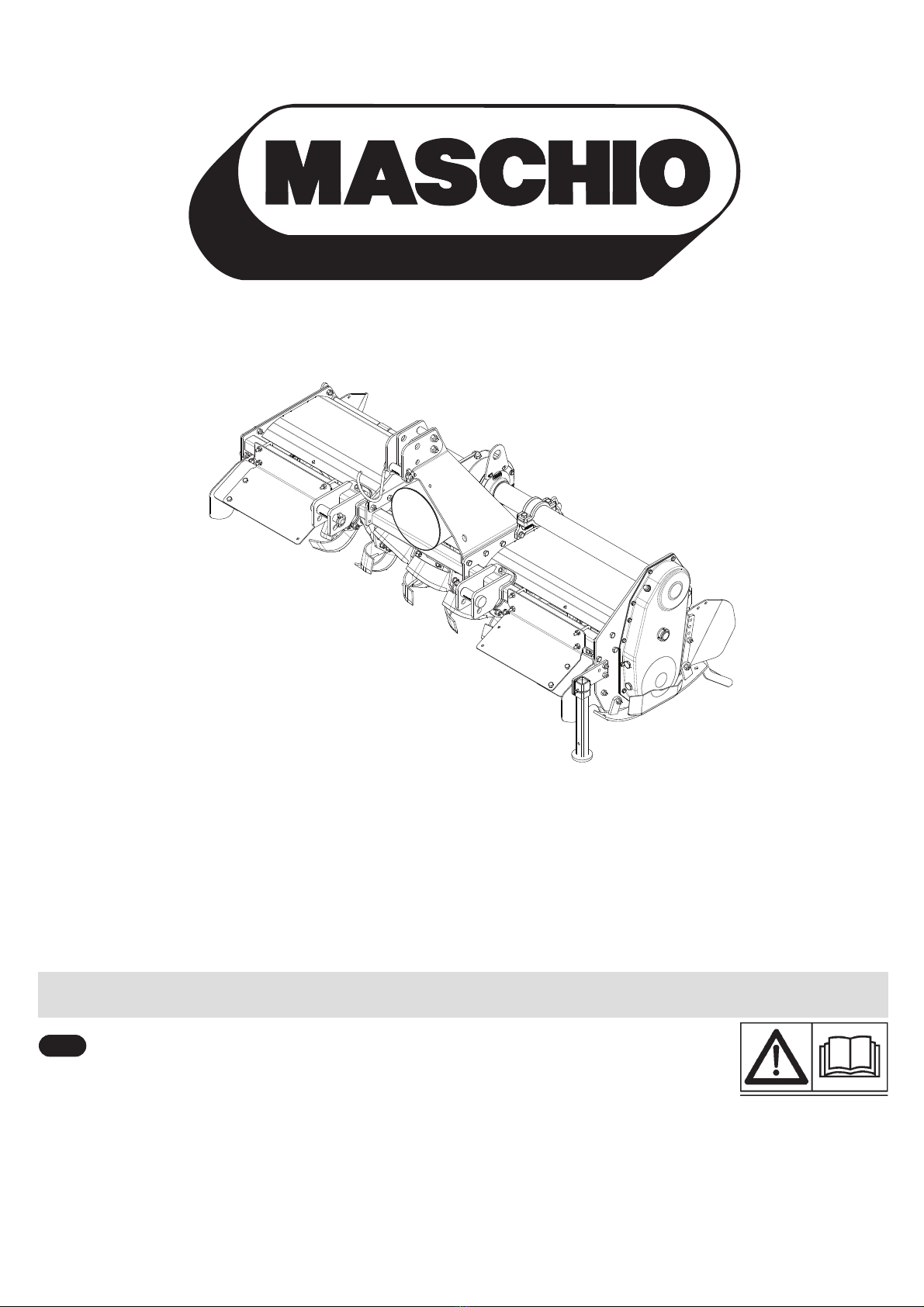
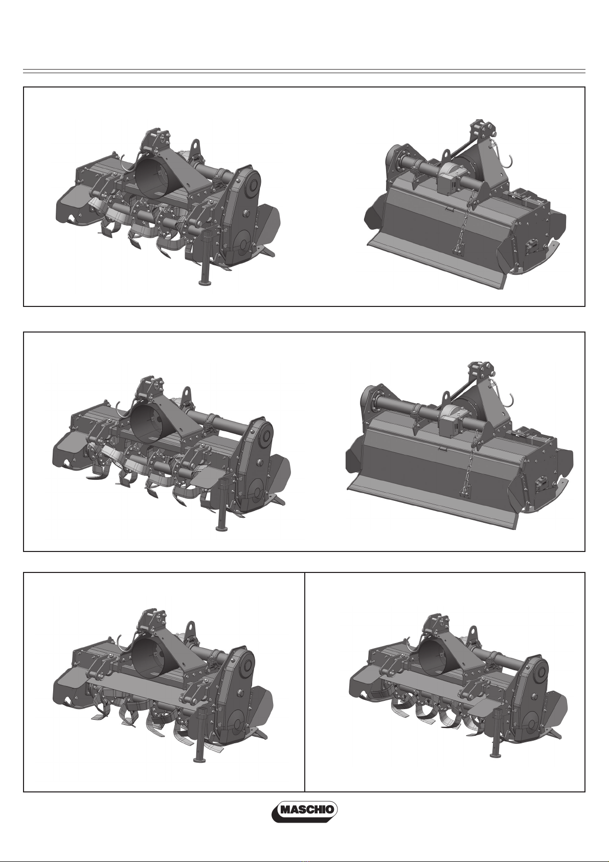
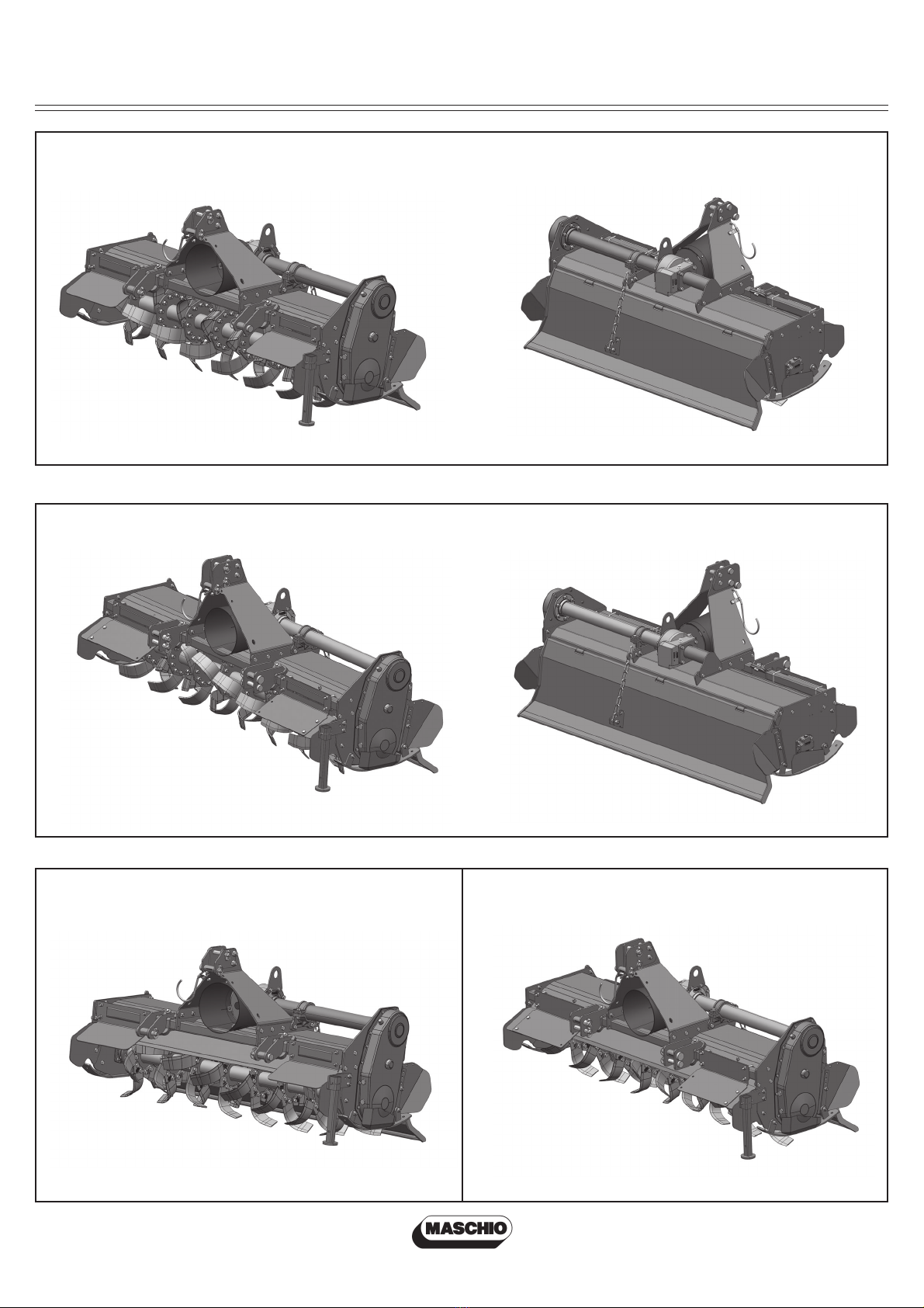
Technical specification
Technical specification.................................. 4
Technical specification - Hitch...................... 8
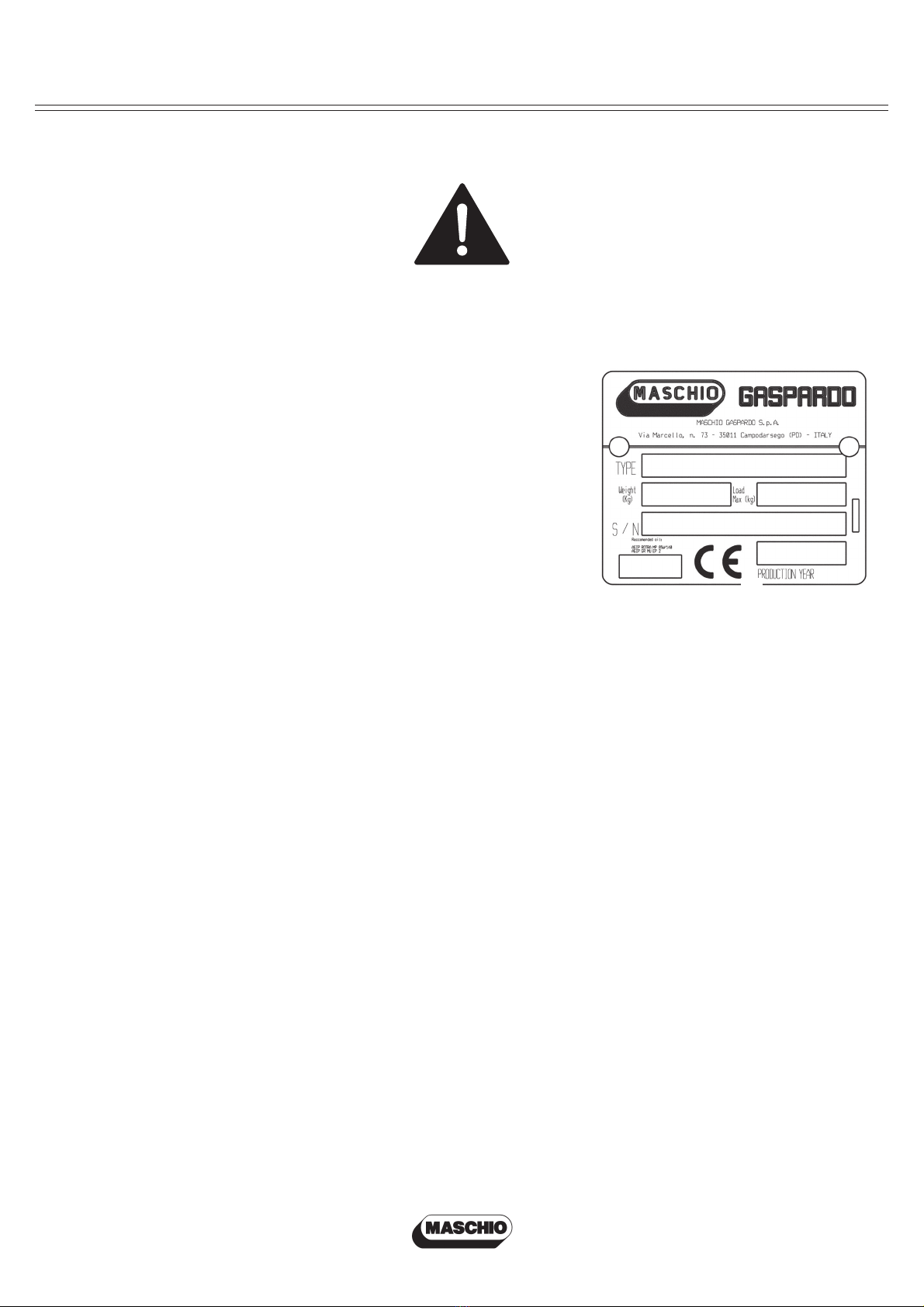
Safety signs
Safety-Alert symbol ...................................... 9
Machine identification................................... 9
Serial no label............................................... 9
Machine safety labels................................... 9
Labels and positions
Machine safety labels and positions............. 10
Machine labels and positions....................... 11
Preparing the vehicle
Preparing the tractor..................................... 12
Park vehicle safety........................................ 12
Stay clear of rotating drivelines .................... 12
Installing
Installing tiller on tractor................................ 12
PTO shaft ..................................................... 14
PTO shaft with clutch ................................... 15
Torque Table / Torque Setting........................ 15
Quick Coupler (optional)............................... 16
Park vehicle safety........................................ 16
Stay clear of rotating drivelines .................... 16
Removing
Removing tiller.............................................. 17
Removing tiller with Quick Coupler............... 17
Operating
Operate safely.............................................. 18
Wear appropriate clothing ............................ 19
Stay clear of rotating drivelines .................... 19
Raising parking stand................................... 19
Lowering parking stand ................................ 19
Levelling attachments (side-to-side)............. 20
Levelling tiller (front-to-rear).......................... 20
Adjusting skid shoes .................................... 20
TABLE OF CONTENTS
Tiller depth adjustment................................. 21
Adjusting levelling board............................... 21
Tilling tips..................................................... 22
During tilling ................................................. 22
Replacement parts ....................................... 22
Service Machine Safely
Practice safe maintenance........................... 23
Wear appropriate clothing ............................ 23
Stay clear of rotating drivelines .................... 23
Service lubrication
Service lubrication........................................ 24
Every 8 work hours / After every use............ 24
Every 50 work hours / ~Every week ............. 24
Every 400 work hours / ~8 weeks................. 24
Lubricant points............................................ 25
Lubricants..................................................... 25
Screw tightening torques.............................. 25
Service
Service intervals........................................... 26
Replacing tines............................................. 26
Tines............................................................. 26
Troubleshooting
Using troubleshooting chart ......................... 27
Storing machine
Storing tiller .................................................. 28
Removing tiller from storage......................... 28
Assembly / Spare parts
WW 6042-6042R-6049-6049R-6062-6062R
.....30
WW 6073-6073R...........................................34
Installing safety guards................................. 38
Installing reverse shield................................ 42
Lift hook assembly procedure ...................... 44
Installing driveline on tiller ............................ 44
Spare parts................................................... 44