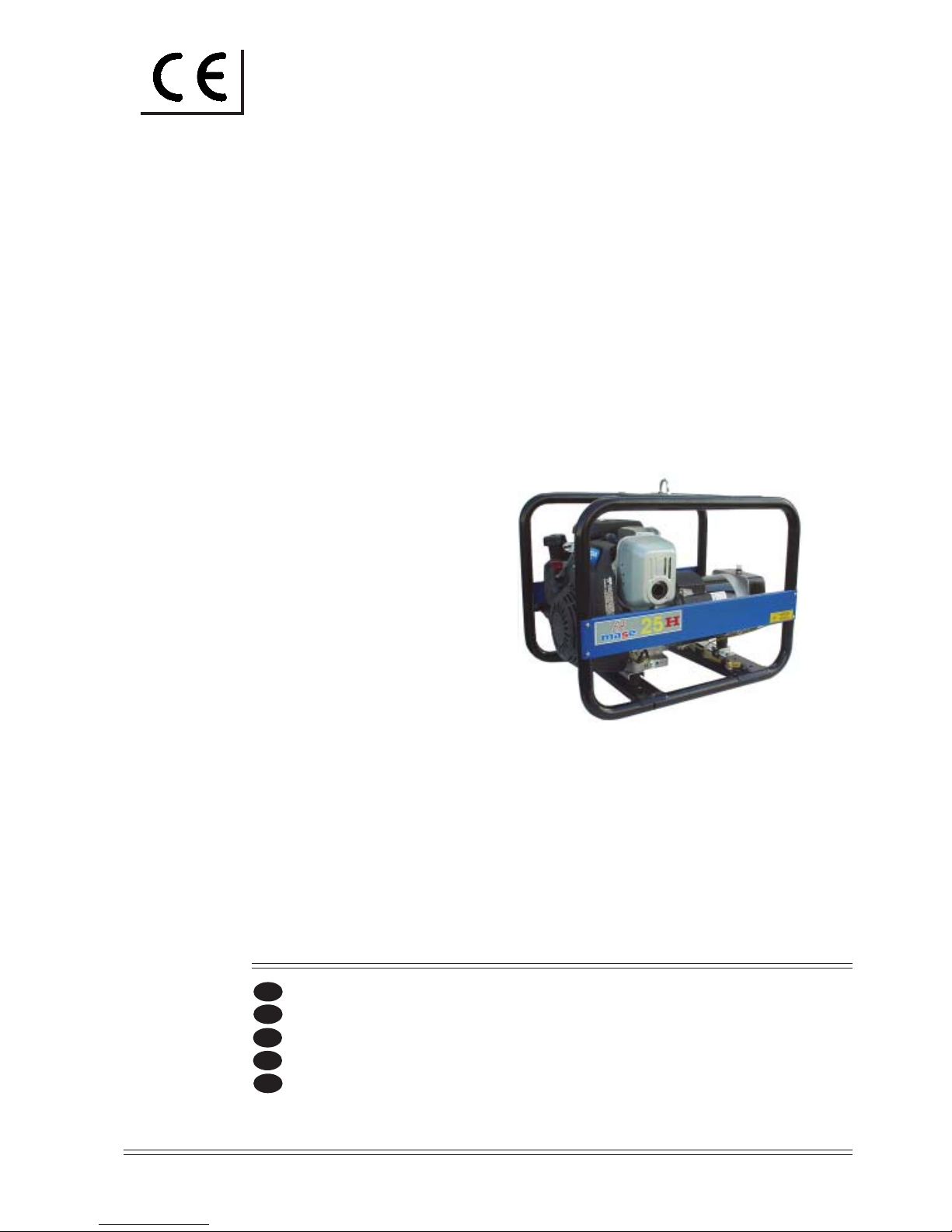
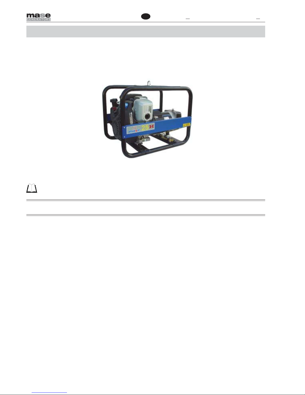
Mase EA 25 H User manual

EA 25 H
REV.2 A.A. 30-04-02 cod.41758
MANUALEDIUSOEMANUTENZIONE
USEANDMAINTENANCEMANUAL
GEBRAUCHSANWEISUNGUNDWARTUNGSVORSCHRIFTEN
MANUELD’INSTRUCTIONSETD’ENTRETIEN
MANUAL USO Y MANTENIMIENTO
masemase
masemase
mase
GENERATORS
I
GB
F
E
D

-2-
EA 25 H
1
2
3
2
5
1
4
Rated power factor
Mass
Rated current
Declared frequency
Rated power
Rated voltage
Kg
A
V
Hz
Year of manufacture
Code
Degree of Protection
Class of isolation
Temp.max of use
Altitude Max. of use
°C
mt.
Rated voltage
Rated current
XXXXX
s.p.a. - Via Tortona
e-mail: mase@masegenerators.com
www.masegenerators.com
MASEGENERATORS
47023 CESENA(FC) Italy
Rated power
Noise level Lwa
**
W
IP
**
**
**
**
**
**
**
**
**
**
**
**
**
**
**
**
**
**
**
**
**
**
**
**
1
SERIAL No. 16
2
4
5
6
10
11
13
14
7
8
9
12
3
14

-3-
EA 25 H
3
4
5
2
3
45
6
4
1
23
1

-4-
EA 25 H
S.A.E
Service
Grade
-30 -20 -10 0 10 20 30 40
Ambient temperature (
o
C)
40
20W
20W40
20
30
5W
5W30
10W
10W30
Fig.6

-36-
GB EA 25 H
PRELIMINARY PRESCRIPTIONS
CAMPO D’IMPIEGO:
THE GENERATOR GROUP IS PROPER FOR TO PRODUCE IN WAYAUTONOMOUS ELECTRIC ENERGY IN THE
LIMITS OF TENSIONAND WATT DECLARED BY THE BUILDER
Carefully consult this manual before using or carrying out any operation on the generator.
FAILURE TO RESPECT THE SPECIFICATIONS CONTAINED IN THIS USE AND MAINTENANCE MANUAL WILL
RESULT IN FORFEITURE OF THE GUARANTEE ON THE PRODUCT.
This manual was drawn up by the manufacturer and forms an integral part of the generator equipment, definition used as
indicated in Directive 89/392 EEC; the information contained in the manual is addressed to all the persons involved in the
operating life cycle of the generator, and is necessary to inform both those who effectively carry out the different opera-
tions and those who coordinate the activities, to arrange the necessary logistics and to regulate access to the place
where the generator will be installed and operated.
This manual was drawn up by the manufacturer with the purpose of providing essential information and instructions for
proper use and maintenance in conditions of safety. It constitutes an integral part of the generator equipment and must
carefully be protected from any agent which may damage it for the entire life cycle of the generator. The manual must
accompany the generator if transferred to another user or owner.
The manual defines the purpose for which the generator was constructed and contains all the information necessary to
guarantee safe and proper use.
Constant observance of the instructions contained in this manual guarantees the safety of the operator, protection
against damage to persons or things, operating economy and a longer life of the generator.
The drawings are provided by way of example. Even if the generator in your possession differs from the illustrations
contained in this manual in elements of little significance, for example the colour, the safety of the generator and the
information provided are nevertheless guaranteed.
To facilitate consultation, it has been divided into sections identifying the main concepts; for a quick look at the topics,
consult the index.
Ongoing improvement and development of the product may have led to modifications to the generator which are not in-
cluded in this publication.
Whenever a problem concerning the generator or this publication arises, consult with Mase Generators
SPA for the latest information available.

-37-
GB
EA 25 H
1. GENERAL SAFETY WARNINGS
1.1 Symbology / Definitions in the manual
Those parts of the text not to be ignored are highlighted in bold type preceded by a symbol, as illustrated and defined
below.
Indicates that particular attention must be paid in order to prevent running serious risks which
could lead to death or possible harm to the health of personnel.
A condition which may occur during the lifetime of a product, system or plant considered at risk
regarding damage to persons, property, the environment or economic loss.
Indicates that particular attention must be paid in order to prevent serious consequences which
could result in damage to tangible goods, such as the resources or the product.
Instructions of particular importance.

-38-
GB EA 25 H
1.2 Simbology on electrogen group
STOP
cod. 42109
cod. 42132
cod. 42117
cod. 42116
cod. 42114
cod. 42111
cod. 42115
cod. 42110
cod. 42108
cod. 42118
Cod.46095

-39-
GB
EA 25 H
1.2.1 Meaning of safety labels
• These labels warn the user of any danger which may cause serious injury.
Carefully read the meaning and the precautions described in this manual
• If the label detaches or becomes illegible, replace it with a new one which can be requested from an authorised
Mase dealer.
Danger Symbols Meaning
· Caution to avoid burns, do not touch during operation.
The exhaust manifold and the engine, pay attention to the labels on the generator.
· Leave the engine to cool down before storing it indoors
· Read and understand the Use and Maintenance Manual before starting the generator.
· The Mase generator has been designed so as to guarantee
safe and reliable operation provided that the instructions are followed. Otherwise,
personal injury or damage to the equipment may result.
· The exhaust gases contain toxic carbon monoxide.
· Never operate the generator in a closed space.
·Provide for adequate ventilation. If installed indoors, scrupulously observe the ventila-
tion regulations.
· The fuels are highly flammable and in certain conditions also explosive.
· Fill up in a well-ventilated area with the engine off
· Do not smoke or create sparks while filling up
· Immediately clean off any fuel leaks.
Danger of electric discharge: consult the manual
Danger of sudden starting of the remote starting device.
Before carrying out any operation on the generator deactivate the remote starting
device
STOP
Obligation Symbols Meaning
Obligation to connect the generator to earth

-40-
GB EA 25 H
Prohibition Symbols Meaning
The connections to an emergency electric network must be carried out by specialised
electricians in compliance with the relevant regulations in force. Improper connections
may cause current feedback from the generator to the electrical lines connected. These
current feedbacks may cause electroconduction to the people working for the electricity
company or who come into contact with the lines during the failure. Moreover, once the
line has been restored, the generator may explode, burn or cause fires in the electrical
system of the facility.
No smoking or use of open flames
Do not clean, lubricate, repair or adjust moving parts.
Do not extinguish fires with water, use homologated extinguishers.

-41-
GB
EA 25 H
1.3 General danger information
• It is recommended to learn how to stop and operate all the controls.
• Do not allow unqualified personnel to use the generator.
• Even though the generator is protected, do not stand near it.
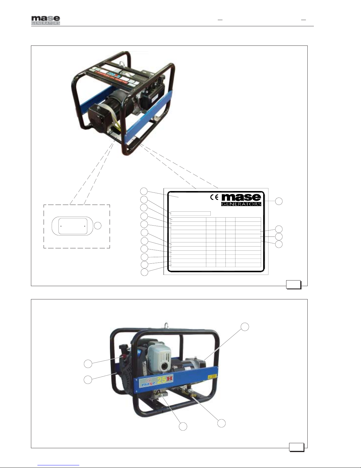
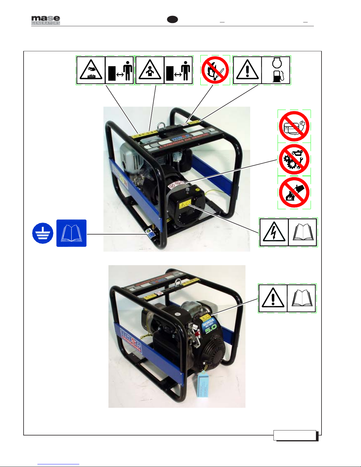
• Do not remove the labels for any reason and request replacement if necessary.
• Before starting the Generator or before starting any lubrication or maintenance operation, it is essential that the per-
sonnel responsible has read and understood all the WARNINGS, CAUTION and DANGER notices in this manual and
in the additional technical documentation provided.
• Before any operation on the generator, ensure that the primary engine is not running and that no parts are moving,
and post a sign saying DO NOT SWITCH ON or similar at the start switch or the controls before carrying out the
maintenance or repair work on the generator.
• Nevertheless, the manufacturer cannot foresee all the possible circumstances which may lead to potential risks in
the effective conditions of use of the Generator.
Any operations and/or procedures for maintenance not expressly recommended or indicated in the user manuals
must always be notified to and approved by the manufacturer.
In the event that a procedure not specifically recommended needs to be applied, the user is responsible for assuring
that such procedure is safe and does not cause harm to persons.
• The manufacturer declines all responsibility for damage to persons or things deriving from inobservance of the safety
regulations.
• Carefully examine the safety warning plates on the generator and respect the relevant instructions.
1.3.1 Danger of entanglement
• Do not remove the original protections from any of the exposed rotating parts, hot surfaces, air intakes, belts and
live parts.
• Do not carry out any maintenance operation with the generator running.
• Do not wear flapping garments, such as scarves, foulards, bracelets, etc. and all garments must be tied with elastic
at the edges.
• Do not clean or carry out maintenance on moving parts
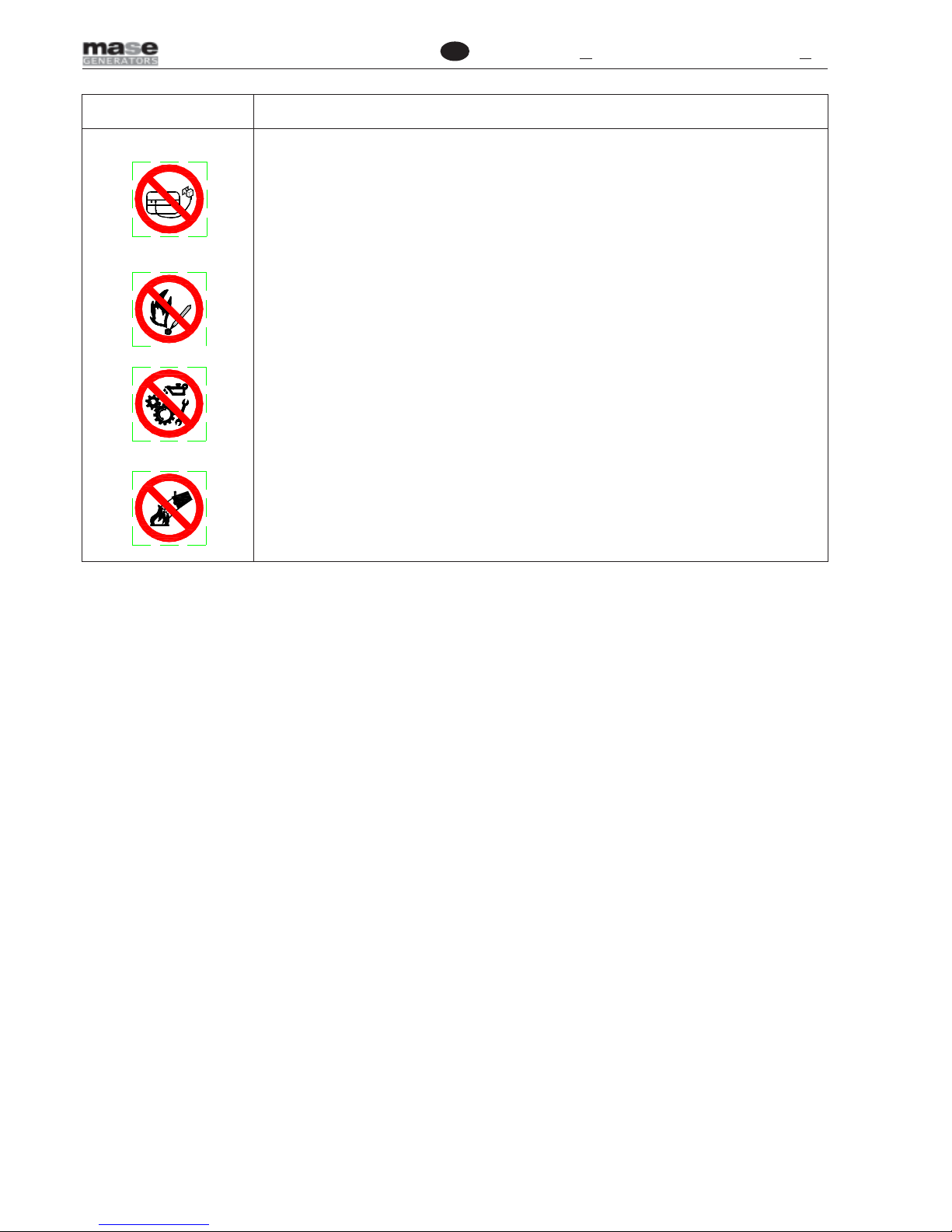
1.3.2 Danger of burns
• Do not permit unskilled persons or without adequate training to use the generator.
• Do not permit children or animals to approach the generator when it is in operation.
• Never touch the exhaust, the relevant protection or the engine body when the generator is running or still hot.
• Do not lean against or sit on the generator for any reason whatsoever.
• Identify the position of the fire extinguishers or other protection and emergency devices and learn their functioning.
• Identify any sources of danger such as fuel, engine oil or acid solution leaks, condensate in the drip caps, high volt-
age, high pressure.
• Do not cause short-circuits by placing keys or tools on the batteries or on the cable fittings.
• The battery fluid contains sulphuric acid which is extremely corrosive and harmful to the skin. Always wear protec-
tive gloves and be extremely careful to avoid spillage when pouring the acid. In the event of contact, wash the affected
part thoroughly with running water and consult a physician, in particular when the eyes are involved.
1.3.3 Danger of harm to hearing
• Do not stand near the generator for long periods without protective earmuffs since hearing may be reduced.

-42-
GB EA 25 H
1.3.4 Danger of intoxication
• The exhaust gases contain toxic carbon monoxide.
• Never use the generator in tunnels or in any place with poor ventilation. If indoor use is inevitable, it is essential to
provide for proper and efficient ventilation in order to prevent intoxication of persons or animals.
• Check that the engine exhaust is free and that the pipes allow evacuation of the exhaust fumes.
• Check that the exhaust gases are discharged to the outside in a safe position away from doors, windows and air in-
takes.
1.3.5 Danger of fire or explosion
• Always turn off the engine before refuelling.
• Do not smoke during refuelling.
• Refuelling must be carried out with extreme care, ensuring that fuel does not overflow from the engine tank respect-
ing the maximum level.
• In the event of fuel spillage from the tank, thoroughly dry and clean the parts involved.
• Check that there are no fuel leaks and that the pipes are undamaged.
• When refuelling has been completed, tightly close the fillercap
• Keep flammable liquids, matches and other explosive and/or flammable products away from the generator, since the
temperature near the exhaust is high during operation.
• Never leave flammable liquids or cloths soaked in flammable liquids in proximity of electrical equipment (including
lamps) or parts of the electrical system.
• The batteries develop hydrogen, a highly explosive gas. It is recommended not to smoke nor cause sparks in the vi-
cinity, in particular during charging.
• Do not obstruct the cooling air inlets/outlets.
• In the event of fire, use a homologated fire extinguisher and never use water.
1.3.6 Danger if failing to use personal protection devices
• The persons responsible for handling must always wear protective gloves and safety shoes.
• Wear safety shoes and overalls.
• If the generator needs to be lifted from the ground, the operators must wear a protective helmet.
• Immediately change wet overalls.
• Use protective gloves.
1.3.7 Danger caused by the engine starting
• Do not leave disassembled parts, tools or anything else not forming part of the system on or near the engine.
• Install the protections necessary for safety on the parts completing the system.
• Operate the generator on a flat surface as far as possible. For continuous operation, the maximum permitted engine
inclination is 20 degrees. Greater inclination of the generator might cause the fuel to leak out or cause problems with
engine oil pressure.
• To prevent the risk of fire and for proper ventilation, position the generator at least 1m (3 ft) from buildings or other
equipment during operation.
• Check the oil level by means of the dipstick.
• Check that all the electrical utilities are off so that the generator is not started on load.
• Check perfect functioning of the devices which stop the generator in the event of failure due to low oil level.
• Identify the position of the emergency stop buttons, switches and other emergency systems on the generator.
• Learn the special emergency procedures relative to the installation in question.

-43-
GB
EA 25 H
1.3.8 Danger of electromagnetic radiation
• Do not allow access to persons wearing a pacemaker because of possible electromagnetic interference with the de-
vice.
1.3.9 Danger of electrocution
• When using the generator always bear in mind that in wet or very humid places and in confined conduction spaces it
is obligatory to comply with Articles 313 and 318 of Presidential Decree No. 547 27/04/55, as well as Chap. 11 Sec-
tion IV of the CEI 64-8 regulation.
• Immediately change wet overalls.
• Insulate all the connectors and detached wires.
• Do not leave the power terminal board of the generator uncovered; check that the electrical power and auxiliary serv-
ice connections have been made properly.
• Do not power loads with a voltage different from that delivered by the generator
• Do not spray water directly onto the electrical parts
• Do not clean the internal electrical parts with compressed air, since short-circuits or other faults may occur.
Do not tamper with the active protections, thermal switches and differential magnetothermal switches.
• In the event of malfunctioning, do not remove the panel to attempt repairing it. Contact Mase specialised personnel.
• Do not access the generator with wet hands, since it is a potential source of electric shock if improperly used.
• Take the necessary precautions to prevent the danger of electrocution; check that the earthing system has been in-
stalled and constructed in accordance with regulations.
• For the safety of the users, the earth connection of the generator must always be carried out paying particular atten-
tion to the cable cross-section used. For the connection of the earth cable use the dedicated terminal on the genera-
tor. For the earth connection follow the indications in the table to select the cable cross-section to use depending on
the generator power. The generator must be connected to earth using a copper cable with a minimum cross-section of
6 mm2.
The manufacturer is not responsible for any damage caused by failure to earth the system.
1.3.10 Danger resulting from bad storage
• Packed and unpacked generators must be stored in a cool and dry place and never exposed to bad weather.
• Avoid stacking packed generators to prevent them from falling causing damage to persons and/or things.
Pwer kVA 1÷10 10÷20 20÷40 40÷60 60÷80
Section mm² 610253550

-44-
GB EA 25 H
2. GENERAL INFORMATION
The generator was designed, constructed and tested to meet the current European and national regulations and to re-
duce the electrical risks to a minimum in compliance with the following regulations:
EEC 73/23 directive: low voltage
EEC 89/392 machine directive
2.1 Reference documents
The instructions for use provided with each generator are made up of a set of documents of which this manual repre-
sents the General Part. Normally, the following documents are provided.
aCEDeclaration of Conformity.
bInstruction manual for use and maintenance of the generators (this manual).
cEngine use and maintenance manual.
dAlternator use and maintenance manual (in case of alternators not manufactured by Mase).
eList of Mase Service Centres.
fMase Warranty certificate.
gWarranty card.
2.2 Facsimile of CE declaration of conformity
The generators constructed by Mase, intended for countries in the European Community, are in conformity with the
applicable EEC Directives and are furnished with an EC Declaration of Conformity (Fig.B).
2.3 Marking
The generator identification plate carries all the identification data in conformity with accordance with the provisions for
CE Marking for those cases where required. Below is a facsimile of the identification plate fixed on the control panel of
each generator (Fig. A).
1 - Manufacturer-Adress
2 - Machinename
3 - Machinecode
4 - Year of construction
5 - Ratedpowerfactor
6 - Declaredfrequency
7 - Ratedpower
8 - Ratedvoltage
9 - Ratedcurrent
10 - Degree ofprotection
11 - Class of isolation
12 - Temperature max. of use
13 - Altitude max. of use
14 - Noiselevel
15 - Weight
16 - Serial number
Fig.A
Rated power factor
Mass
Rated current
Declared frequency
Rated power
Rated voltage
Kg
A
V
Hz
Year of manufacture
Code
Degree of Protection
Class of isolation
Temp.max of use
Altitude Max. of use
°C
mt.
Rated voltage
Rated current
XXXXX
s.p.a. - Via Tortona
e-mail: mase@masegenerators.com
www.masegenerators.com
MASEGENERATORS
47023 CESENA(FC) Italy
Rated power
Noise level Lwa
**
W
IP
**
**
**
**
**
**
**
**
**
**
**
**
**
**
**
**
**
**
**
**
**
**
**
**
1
SERIAL No. 16
2
4
5
6
10
11
13
14
7
8
9
12
3
14

-45-
GB
EA 25 H
NR.000000 mase GENERATORS S.p.A.
Tel. +39 (0) 547 354311
Fax +39 (0) 547 317555
DICHIARAZIONE CE DI CONFORMITÀ
EC DECLARATION OF CONFORMITY
Fabbricante/Manufacturer: maseGENERATORS S.p.A.
Indirizzo /Address : Via Tortona 345, Pievesestina (FC)
Il sottoscritto Luigi Foresti in qualità di direttore tecnico della maseGENERATORS S.p.A., dichiara sotto la
propria responsabilità che il gruppo elettrogeno modello .................... :
The undersigned Luigi Foresti as maseGENERATORS S.p.A. technical manager declares, under his sole
responsability, that the generator model................:
Codice / Code Descrizione / Model Matricola / Serial N.
è conforme alle disposizioni delle Direttive di seguito elencate:
CEE 89/392 (come emendata delle Direttive CEE 91/368 e CEE 93/44)
CEE 73/23 modificata da CEE 93/68.
corresponds to the requirements of the following EEC Directives:
89/392/EEC (as amended by the Directive 91/368/EEC and 93/44/EEC)
73/23//EEC as amended by 93/68/EEC.
Cesena, / /
mase GENERATORS S.p.A. Sede legale ed Amm.: 47023 CESENA (FC) ITALY - Via Tortona, 345 - C.F./P.I. 00687150409 Cap. Soc. milioni 2000
di cui 949 versati - Registro Società Tribunale Forlì n. 6818 - CCIAA Forlì n.164063 - c.c.p. n. 11541471 - EXPORT FO n. 006368
Direttore Tecnico
Technical Director
Fig.B

-46-
GB EA 25 H
2.4 General characteristics
The generators of the EA series have been designed to assure professional users maximum efficiency and reliability for
any type of work. All the models have been developed for heavy duty, using highly reliable 3000 rpm air-cooled benzine
engines and are fitted with low oil pressure protection.
The alternators are type 2-pole, synchronous, self-energized, self-regulating.
2.5 Table of technical characteristics
MODELLO EA 25H
GENERATOR
Synchronous, self-
energised, self-regulating,
two-pole
Type Single-phase
Maximum power 1900 W
Continuous power 1700 W
Maximum power /
Continuous power /
Frequency 50 Hz
Power factor Cos Ø 1
ENGINE
Type
4-stroke, petrol, overhead
valves
Model HONDA GC160
Cooling Forced air
No. of cylinders 1
Fuel Unleaded petrol
Power HP 4,3
Capacity cm3160
Aspiration Natural
Rotation Rpm 3000
Tank capacity lt. 2
Oil sump capacity lt. 0,6
A
utonomy at ¾ load h. 2
Starting
Pull-start with self-winding
cord
GENERATOR
Dimensions (LxWxH) mm 595 x 430 x 460
Weight kg 36
Sound power Lwa 98
230V400V

-47-
GB
EA 25 H
2.6 Generator composition
The generators ofthe EA series areessentiallycomposed
of the following components:
-Engine air filter (Fig. 4 Ref. 3)
-Knob for pull-start
-Petrol-powered internal-combustion engine (Fig. 2
Ref.1)
-Terminalforearthconnectionofgenerator(Fig. 2 Ref.
2)
-Alternator unit (Fig. 2 Ref. 3)
-Instrument and outlet panel (Fig. 3 Ref. 1)
-Engine exhaust (Fig. 3 Ref.2 )
-Load-bearing chassis (Fig. 3 Ref. 3)
-Lifting hook (Fig. 2 Ref. 4)
-Fuel tank (Fig. 4 Ref. 4)

-48-
GB EA 25 H
3. INSTALLATION
3.1 Positioning the generator
The generators of the EA series must be positioned horizontally, i.e. placed on a flat surface or made to sit horizontally
by placing shims under the support feet.
The engine functions properly if it does not exceed a maximum inclination of 20 °, both on the longitudinal and the
transversal axis. Should the engine be operated in conditions at a greater inclination, there is a risk of insufficient
lubrication or suction of engine oil from the air filter.

-49-
GB
EA 25 H
4.1 Starting
Before starting the generator, check that:
-the engine stop switch is in position “ON” (Fig. 2 Ref. 4)
If the engine is cold, turn the start lever to bring nearer before trying to start (Fig. 4 Ref. 1)
(if the engine is hot, the start lever need not be turned to the right).
Proceed by resolutely pulling the self-winding cord (Fig. 2 Ref. 1) to start running the engine.
Repeat the operation if the engine does not start after the first attempt.
As soon as the engine has started, return the start lever to its original position.
Beforeconnectinganyutilityleavetheenginetorunforafewminutessothat it gradually reaches the operating temperature.
Each generator is equipped with one outlets:
-both single-phase (Fig. 3 Ref. 6)
The power available for the outlets is that indicated on the adhesive label carrying the technical characteristics.
To prevent damage to the self-winding cord, never release it suddenly after pulling it to full
travel, but guide it back until completely rewound.
The generator engine has been calibrated, in idle, to 3120 rpm equal to 52.5 Hz, as the engine stabilises at about
3000 rpm equal to 50Hz with a load. For this reason, the accelerator lever must never shift for any reason, since
the output voltage, frequency and power values of the generator would be compromised.
4 . USING THE GENERATOR
The available power is as indicated on the adhesive label carrying the technical characteristics (Fig.A).
The sum of absorption of all the utilities connected to the generator must never exceed the continuous power
value of the generator.

-50-
GB EA 25 H
4.2 Protections
The generators of the EA series are fitted with a series of protections which protect them from improper use and faults
which may compromise integrity of the generator and operators.
-Low oil pressure protection
Trips turning off the generator when the pressure in the lubrication circuit is insufficient; when it trips, no warning light
comes on; therefore, if the generator stops, always check the oil level to ensure that this is not the cause of the
generator stopping.
Generally, it suffices to fill up with oil in order to restart the generator.
The low oil pressure protection does not give an indication of the oil level. The oil level must periodically be
checked in order to prevent damage to the engine.
- Protection against short-circuit and overload
For protection against short-circuits and overloads, the generators have been fitted, depending on the various versions,
with magnetothermal differential / magnetothermal / differential switches which trip, cutting the power, if there is an
overload condition on the alternator, or a short-circuit or current leakage to earth.
To restore the thermal switch contact, after having identified and eliminated the cause of the cut-out and waiting for
about a minute, press the thermal switch button resetting it to the original position (Fig. 3 Ref. 5).
Danger of electric discharge: consult the manual. Do never touch the pot or the protection pot so that to
avoid scorching.
La somma degli assorbimenti degli utilizzi collegati al gruppo elettrogeno non deve mai superare il valore della potenza
continuativa di questo.
4.3 Stopping
Before switching off, disconnect any loads connected to the outlets, close the fuel tap and let the engine idle for about 10
seconds.
To switch off the engine, position the on/off switch to “OFF” (Fig. 2 Ref. 4).

-51-
GB
EA 25 H
5. CARE AND MAINTENANCE
5.1 Preamble
Any maintenance operation on the generator must be carried out with the engine off and leaving it to cool
down sufficiently, and must only be carried out by authorised and suitably trained personnel.
It is recommended to scrupulously follow the instructions in the manual provided by the engine manufacturer with each
generator.
It is important to regularly inspect and carry out maintenance on the generator. The frequency of maintenance should be
decided on the basis of the number of hours of operation.
5.2 Ordinary engine maintenance
The periodic maintenance operations to be carried out on the engine are indicated in the table at point 5.7. For more
detailed information consult the manual provided by the engine manufacturer with each generator.
- Check the oil level with the cap/dipstick. (Fig.5, ref.1).
The oil level must always be between the MAX and MIN notches on the dipstick.
- When checking the oil level, ensure that the generator is positioned horizontally.
5.3 Engine oil change
Check the engine oil level with the dipstick positioned on the oil fillercap (Fig. 5 Ref. 1).
Check the oil only with the engine is positioned on a flat surface and the oil filler cap not screwed down but only resting.
If the engine oil level is low, top up using only classified multigrade oils SE, SF, SG, SH in accordance with the API
classification system.
Tochange the engine oil, removethe fillercap and thedrain plug (Fig. 2Ref. 5) and let the oil flow into acollection container.
It is recommended to carry out this operation with the oil hot for easier drainage.
Close the drain plug and pour in the necessary quantity of oil to fill the oil sump to the maximum level; oil sump capacity
0.6 l.
Always check correct viscosity of the engine oil in relation to the range of ambient temperatures in which the
generator operates as indicated in the table in Fig.6.
Dispose of the used oil in an appropriate manner, since it is a polluting product.
Take the used engine oil to special collection centres for disposal.
- Protect hands from contact with oil by wearing gloves.
In the event of accidental contact with engine oil, thoroughly wash the affected part with soap and water.
- During oil top-up and refuelling, respect the maximum level indication. An excessive quantity of engine oil
may cause damage to the engine.
Table of contents
Other Mase Inverter manuals