11
HYS006773
08 09 1 006 07
[2] AC Volt age
Range
200mV
2V
20V
200V
Resol ution
0.1mV
1mV
10mV
0.1V
Accur acy
(50 ~ 60H z)
±(0.8 %rdg+ 5dgt)
(30~50Hz,60~10KHz)
±(2%r dg+10 dgt)
600V 1V
• Input i mpeda nce; 10 MΩ
[3] DC Voltag e
Range
200mV
2V
20V
200V
Resol ution
0.1mV
1mV
10mV
0.1V
Accur acy
±(0.7 %rdg+ 3dgt) 1 0MΩ
600V 1V
Input i mpeda nce
[4] Res istan ce
Range
200Ω
2KΩ
20KΩ
200KΩ
Resol ution
0.1Ω
1Ω
10Ω
0.1KΩ
Accur acy
±(1%r dg+2d gt)
250V DC or AC rms
(by PTC
protection circuit)
2MΩ 1KΩ
Over load protection
20MΩ 10 KΩ ±(2% rdg+5 dgt)
[5] Tempera ture
Range
-20°C t o
1000° C
Resol ution
1°C
Accur acy
-20°C t o 0°C
0°C to 40 0°C
400°C t o 1000° C
±(5.0 %rdg+ 5dgt)
±(1.0 %rdg+ 3dgt)
±(2.0 %rdg+ 3dgt)
-4°F to
1832° F
1°F -4° F to 32°F
32°F to 7 52°F
752°F t o 1832° F
±(5.0 %rdg+ 5dgt)
±(1.0 %rdg+ 3dgt)
±(2.0 %rdg+ 3dgt)
[6] Dio de chec k
Test curr ent : 1mA
[7] Con tinui ty
If the re sista nce und er testing c ircui t less th an 50Ω, buzz er will
sound .
4. Operating instruction
4-1 LPF usage
The met er have L ow- Pas s-Filter t o reduc e the inf luence of hi gh
frequ ency no ise abo ve 1KHz(3d b). This LPF f eatur e is avai lable
in all AC Vol tage or AC C urren t measurem ent mod e.
The “LP F” butt on is act a s ON/ OFF swi tch for L PF circ uit
conne ction . When LP F is activat ed, Mos t of nois e above 1KHz
will de cay gre atly. So we can o btain m ore stable a nd accu rate
readi ngs on lo w frequ ency respo nse.
4-2 Data HOLD
The pus h key is us ed to mai ntain the me asure ment da ta
uncha nging .
Press “ HOLD” p ush key t o inter and ex it the ho ld mode i n any
mode. That a ct with t rigge r. The m eter wi ll resu me th e norma l
measu remen t mode by p ressing th e key aga in.
4-3 Range swi tching
“RANGE” butto n is the au to/ma nual measu remen t push ke y that
act wit h trigg er. Th e defau lt is aut o measurem ent whe n power o n.
Press t his key o nce, wi ll switch to m anual m easur ement mode ,
and the n press o nce aga in, will swi tch to au to meas urement mo de.
4-4 Functio n switching
“FUNC” k ey is use d as the fu nction sel ectio n key tha t acts with
trigg er. Use th e key as sw itch of DC/A C, Diod e/ Cont inuity and
°C/°F.
4-5 Maximum v alue hold
“MAX” ke y is act wi th trig ger. Press th is key on ce, the m aximum
value i s holdi ng(wi ll Display s “MAX” s ymbol o n the LCD ), an d the
press o nce aga in, wil l switch to no rmal Me asure ment mode.
After p ressi ng the ke y, A/ D wil l keep wo rking , and the d isplay
value a re alwa ys up dat ed and keep th e maxim um valu e.
4-6 Back Ligh t
“ ” Push ke y is used c ontro l Black Ligh t. When p ress th is
key and h eld mor e than 2s ec, will ena ble Bac k Light f or 15se cs.
Press t he key ag ain wit hin 15secs , back li ght wil l disable.
4-7 Sleep mod e (Auto power O FF)
If the me ter is id le for mo re than 15mi nutes , the met er
autom atica lly tur ns the power o ff.
In this s leep mo de, the m eter is save b atter y energ y.
In the sl eep mod e, the me ter may be tur ns norm al oper ating
mode by “ RANGE ”, “MAX ”, “ ” Ke y and rot ary swi tch.
There a re two wa ys to dis abl e the sle ep mode a s follo wing:
(1) In th e auto po wer off stat e , you are p ush ing “HO LD” key.
(2) Pus h and hel d “HOLD ” key, turn on po wer b y rotar y switc h
at the sa me time .
5. Measurement operating
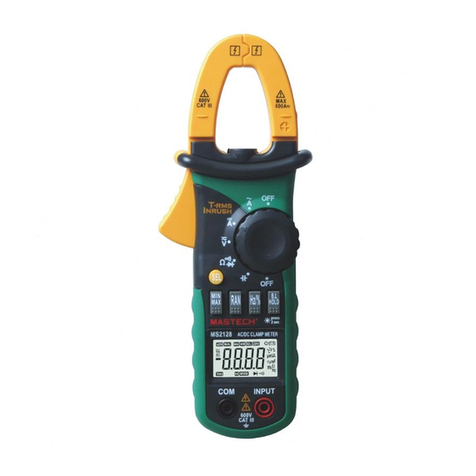
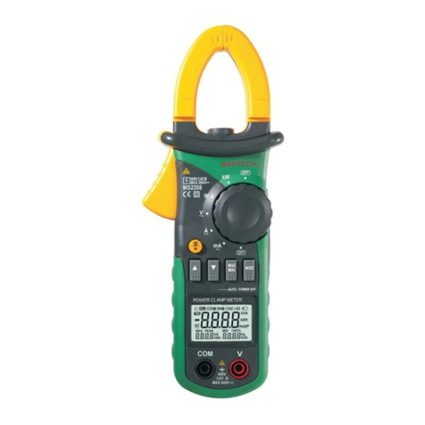
5-1 AC Current mea surement
1. Set th e rotar y switc h to th e desir ed “A~” p ositi on.
2. Pres s the cla mp trig ger to open ja w and to cl amp one c onductor
only, makin g Sure th at the ja w is firm ly cl osed ar ound th e
condu ctor.
3. Set th e condu ctor in t hat flow the m easur ed curr ent to centr e
posit ion of ja w as far as P ossible. I n this ti me, mea surement
accur acy is be st.
4. Read c urren t value o n the LCD disp lay.
Not: (1 ) Use the L ow Pass F ilter by pus hing “L PF” but ton if
neces sary.
(2) Whe n measu remen t the c urren t of tran smiss ion line, mu st
be clam p one lin e only be twe en the tw o line .
5-2 Leakage c urrent meas urement
This me ter can m easur e the leakag e curre nt on the o ne-phase o r
three -phas e circu it equipme nt as wel l as the co nductor in t hat flo w
the lea kage cu rrent .
1. Set th e rotar y switc h to th e 20mA~ r ange.
2. Clam p the con ducto r in that flow t he leak age cur rent, and th e
read th e leaka ge 0cur rent value o n the LCD d ispla y.
5-3 DC/AC Voltage measu rement
1. Set th e rotar y switc h to th e “V” posi tion. The DC m ode is de fault
mode. To switc h to the AC me asure m ode mus t be pr ess onc e
time th e “FUNC ” butto n.
2. Inse rt the re d test le ad in to the “IN PUT” te rmina l and the blac k
test le ad into t he “COM ” ter minal .
3. Conn ect the t est lea d across wit h the obj ect bei ng measure d.
The measur ed valu e will be s how on th e LCD displa y.
Note:
When DC o r AC volta ge meas urement ha s been co mplet ed,
disco nnect t he conn ection bet ween th e test le ad and circu it
under t est.
5-4 Resista nce measure ment
1.Set th e rotar y switc h to the “ Ω ” posit ion.
2.Inse rt the re d test le ad into the “I NPUT” t ermin al and black t est
lead in to the “C OM” ter minal.
3.Conn ect the t est lea d across wit h the obj ect bei ng measure d.
The measur ed valu e will be s how on LC D display.
Note:
• The tes t lead ca n add 0.1Ω to 0.2Ω of er ror to resis tance
measu remen t.
• To obtain p recis ion reading in low- resis tance m easur eme nt,
that is t he range of 200Ω , short t he input ter minal w ith the t est
lead pr obe, an d then re ad out the con tact re sista nce of te st lead.
After me asuri ng you ca n subtract t he readied conta ct resi stance
value f rom the reading value.
• For hig h resis tance m easureme nt (>10 MΩ), it i s normal tak ing
sever al seco nds to obtain sta ble readin g.
• If The LC D displ ay “OL” sym bol ,it is ind icati ng open circu it for the
teste d resis tor or th e resistan ce value of resi stor is higher th an
the max imum range of th e meter .
5-5 Diode che ck
The dio de chec k funct ion used to ch eck dio de, tra nsistor an d other
semic onduc tor dev ice.
In the di ode tes ting, t he meter sen ds a curr ent thr ough the
semic onduc tor jun ction, and t hen mea sure th e voltage dr op acro ss
the jun ction . A good silic on junc tion wi ll drop b etw een 0.5 V to 0.8V.
1. Set th e rotar y switc h to th e “ ” posit ion.
2. Inse rt the re d test le ad into the “I NPUT” t ermin al and the bla ck
test le ad into t he “COM ” Ter min al.
3. For fo rward v oltag e drop readi ng on any s emico nductor
compo nent, p lace th e red test lea d on the co mpone nt anode and
place t he blac k test le ad on the comp onent c athod e.
The measur ed forw ard dro p volta ge will show o n the LCD d ispla y.
4. Reve rse the t est lea d and measur e the vol tage ac ross the dio de
again .
• If diode is good , the dis play sh ows “OL”.
• If diode is shor ted, th e displ ay shows “0” (z ero) in b oth dir ection.
• If disp lay sho ws “OL” i n dir ectio n, the di ode is op en.
5-6 Continu ity check
1. Set th e rotar y switc h to th e “ ” posit ion.
2.Pres s the “FU NC” pus h button to sw itch in to cont inuity che ck mode .
3.Inse rt the re d test le ad to the “INP UT” ter minal , and then bla ck test
lead to t he “COM ” termi nal.
4. Conn ect the t est lea d across wit h the obj ect bei ng measure d. If
the res istan ce of a cir cuit under t est is le ss than 5 0Ω, the buzze r
will so und.
5-7 Temper ature measu rement
Note:
• MS320 2 Multi -Func tion Socke t is used a s tempe rature ada pter.
• Use K-t ype the rmoco uple probe .
1. Set th e rotar y switc h to th e “TEMP ” posit ion.
2. In thi s time, L CD will d isplay the e nviro nment t emperatu re.
3. Inse rt the MS 3202 te mperatur e adapt er to the “ INPUT” and
“COM” t ermin al , and th en In sert th e K-typ e therm ocouple pr obe
to the MS 3203 te mpera ture adapt er acco rding t o its polari ty.
4. To change the t emper ature p hysic al unite(° C or °F) , yo u can
press t he “FUN C” push b utton.
6. Maintenance
6-1 Replaci ng the Batter y
When me ter dis play lo w battery in dicat or(sy mbol) on the L CD,
you mus t be repl ace the b attery to ma intai n norma l operatio n.
(1) Dis conne ct and re move all tes t probe s from an y live sourc e and
meter.
(2) Ope n the bat tery co ver on the bot tom cas e by scre wdriver.
(3) Rem ove old b atter y and snap new o ne into t he batt ery holder.
6-2 Fuse repl acement
Repla cing th e defec tive fuse sh ould do ne acco rding to 6-1 secti on
proce dure.
6-3 Cleanin g and Deconta mination
The met er can be c leane d with soft cl ean clo th to rem ove any oil,
greas e or grim .
Do not us e the liq uid sol vent or dete rgent .
7. USB interface with a personal computer(PC)
7-1 Connect t he Meter to PC wi th USB cable
7-2 Install ation of appl ication sof tware
