INSTALLATION
4April 2004 / WHISPER 3,5 / USA
1INSTALLATION
To ensure reliability and durability of the equipment, it is
very important that the installation is carried out with the
utmost care and attention. To avoid problems, such as
temperature problems, noise levels, vibration, etc. the
instructions set out in this manual must be followed and
all installation work must be carried out professionally.
1.1 LOCATION
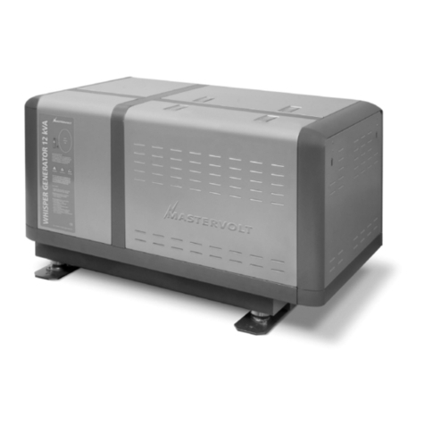
Since Whisper generating sets have extremely compact
dimensions, they can be installed in tight locations.
Consider that even almost maintenance-free machinery
must still remain accessible.
When selecting the location area in which to mount the
generating set, make sure there is sufficient room to car-
ry out any maintenance work. The unit must be easily ac-
cessible on the service side and on the distribution side
to have access to the raw water pump and oil strainer.
Please also note that in spite of the automatic oil pressu-
re sensor it is still essential that the oil level is checked
regularly.
1.2 INSTRUCTIONS FOR OPTIMAL SOUND
AND VIBRATION INSULATION
Position the generating set as low as possible in the
vessel. As the generating set is already secured to the
base frame by means of flexible engine mountings, the
frame can be mounted directly to the vessel’s main struc-
ture.
1.2.1 Steel base plate
However to keep resonant vibrations at a minimum, it is
recommended to mount the generating set on a solid steel
base plate, approx. 1,18" (30 mm) thick weighing approx.
44 kg or 50% of the weight of the generating set. The en-
gine draws its inlet combustion air through several holes
in the capsule base. Therefore the capsule must be fitted
with sufficient clearance between the capsule underside
and the base plate. A steel base plate is available from
Mastervolt as an optional accessory (ref. fig. 12, page
15).
1.2.2 Further recommendations
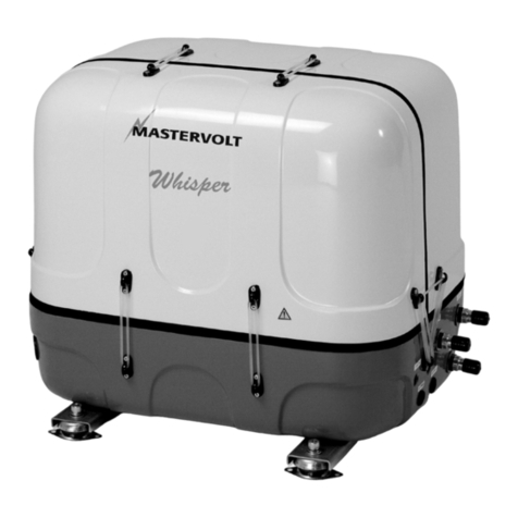
Whisper generating sets are standardly equipped with a
"GRP" (Glass Reinforced Polyester) sound cover. The
canopy has been designed to give effective sound insula-
tion. For optimum sound and vibration dampening, the
following factors should be considered.
1Avoid mounting the generating set in close proximity
to thin walls or floors that may cause resonance.
2Sound dampening is extremely poor if the generating
set is mounted on a light weight flimsy surface such
as plywood which will amplify vibrations. If mounting
on a thinner surface cannot be avoided, this should at
least be reinforced with stiffening struts or ribbing. If
possible, holes should be bored or cut through the
surface to help reduce the resonance. Covering the
surrounding walls and floors with a heavy coating
plus foam will certainly improve the situation.
3Never connect the base of the generating set directly
to bulkheads or tanks.
1.3 VENTILATION
The generating set normally draws air from the engine
room. Engine rooms with natural ventilation must have
vent openings of adequate size and location to enable
the generating set to operate without overheating. To
allow an ample supply of air within the temperature limits
of the generating set an opening of at least 15 square
inches (100 cm2) is required.
A"sealed" engine compartment must have a good ex-
traction ventilator to maintain reasonable engine room
temperatures. High temperature of intake air reduces en-
gine performance and increases engine coolant tempe-
ratures. Air temperatures above 104 ° F (40°C) reduce
the engine power by 2% for each 9° F (5°C) of rise. To
minimise these effects the engine room temperature
must not be more than 27° F (15°C) above the outside
ambient air temperature.
Apply a combination of ventilators, blowers and air intake
ducting to meet the temperature limit. The air inlet ducts
should run to the bottom of the engine room to clear
fumes from the bilge and to circulate fresh air. Air outlets
should be at the top of the engine room to remove the
hottest air. An engine room blower should be used as an
extraction ventilator to remove air from the engine room.
In cases where it is impossible to meet the above mentio-
ned temperature limit by using machine room ventilation,
connections are to be made for an air inlet directly to the
enclosure. With these connections the generating set can
be directly connected to an air duct.

