Matrix Elektronik AG (Manufacturer) Tippkemper - Matrix GmbH
Kirchweg 24 CH-542O Ehrendingen Meegener Str. 43 D-51491 Overath
Tel.:+41 56 20400-20 Fax -29 Tel.:+49 2206 9566-0 Fax -19
Page2of2
LED
Potentiometer
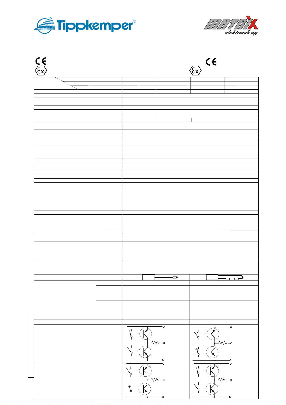
withdustproofpackingscrew
Wiring
IDN/IDD-11xxP-GD:
1 +24VDC
20V
3 Output
4 Input Teach-In
white Cable shield
yellow-green PE
Dimensions and
wiring
IDD-11xxP-GD
IDN-11xxP-GD:
1234567890123456789012345678901
1234567890123456789012345678901
1234567890123456789012345678901
1234567890123456789012345678901
1234567890123456789012345678901
1234567890123456789012345678901
1234567890123456789012345678901
1234567890123456789012345678901
1234567890123456789012345678901
1234567890123456789012345678901
1234567890123456789012345678901
9932 135
M30 x 1,5
Dimensions and
wiring
IDN-11xxP-GD-S99:
Wiring
IDR/IDN-11xxP(-GD)-S99:
1/brown +24VDC
2/white Input Teach-In
3/blue 0V
4/black Output
5/grey PE
1234567890123456789012345678901
1234567890123456789012345678901
1234567890123456789012345678901
1234567890123456789012345678901
1234567890123456789012345678901
1234567890123456789012345678901
1234567890123456789012345678901
1234567890123456789012345678901
1234567890123456789012345678901
1234567890123456789012345678901
1234567890123456789012345678901
9932 135
M30 x 1,5
Socket M12,5pins
With
dustproof
protection
LED
Potentiometer
IDN:Withdustproofpackingscrew
LED
Potentiometer
12345678901234567890123456
12345678901234567890123456
12345678901234567890123456
12345678901234567890123456
12345678901234567890123456
12345678901234567890123456
12345678901234567890123456
12345678901234567890123456
12345678901234567890123456
12345678901234567890123456
12345678901234567890123456
6732 103
M30 x 1,5
Wiring
IDR-11xxP:
1 +24VDC
20V
3 Output
4 Input Teach-In
white Cable shield
yellow-green PE
Dimensions and
wiring
IDR-11xxP-S99(socket)
IDR-11xxP(cable):
Equipotential
bonding
prescription
for Ex devices:
The end of the cable must be
connected outside the
hazardous location. Check the
reliable, noncorrosive holding
of the protection earth
connection.
The cable shield is to connect to PE in a wide area.
123456789012345678901234567890121234567890123456
1
2345678901234567890123456789012123456789012345
6
123456789012345678901234567890121234567890123456
123456789012345678
123456789012345678
123456789012345678
123456789012345678
123456789012345678
123456789012345678
123456789012345678
Exzone Connection "Teach-In"
TEACH-IN, min. hold time: >= 180ms
4 / S99:2
1+ 24VDC
Teach-In
Contact NO or PNP
Installation prescriptions for hazardous locations
It is necessary to take into consideration the valid international and national
rules and regulations (EN 60079-14). The local equipotential bonding have
to be done. The protective earth (PE) is solid connected with the housing.
The maximum input voltage Um=30VDC must not be exceeded. The cable
have to be installed and protected against damages. The cable with
termination fittings, or in cable tray systems and installed in a manner to
avoid tensile stress at the termination fittings. To connect cables inside
hazardous locations only use certificated Ex housings. All cable terminals
must be connected outside hazardous locations. Other then original
manufacturer, additional optical lenses are not allowed in hazardous
locations. In Ex zones 21 and 22, do not operate the sensors without fixed
dustproof sealing crew. After adjust the potentiometer, the dustproof sealing
crew with undamaged packing ring, must be screwed down. Damaged or lost
screws or packing rings must be replaced.
Type IDD-11xxP-GD: Applicable in Ex zones 1, 2, 21, 22.
Type IDN-11xxP-GD: Only applicable in Ex zones 2, 22.
Type IDN-11xxP-GD-S99: Only applicable in Ex zones 2, 22. Do not
separate the connector when the supply voltage is connected to the cable.
When installing the sensor, the safety lock device must be fitted at the cable
connector. The additional adhesive warning label must be fixed to the
connector housing at the connection cable. Lumberg cordsets RKTS 5-298/
xx (Straight type) RKWTH 5-298/xx (Right angle type), are allowed ONLY.
It is necessary to take into consideration the mounting prescription of the
connector manufacturer. In dusty locations, the protection cap for the
sensor socket must be fitted, when no connection cable is connected.
General mounting prescriptions:
Do not exceed the maximum ratings. The electrical connections must be
exactly as shown in the connection diagram. The cable shield must be
connected short. The cable shield should be connected to the protection
earth, large-surfaced. Connection cables must not be installed parallel to
high voltage cables. The cable shield is to connect at PE.
TEACH-IN
Because the IDENTIX sensor compares a memorized reference value with
a actual measure value, first a reference value must be memorized. The
reference value will be picked-up by the TEACH-IN function and
memorized in an EEPROM. (Data holding >= 5 years). TEACH-IN is
activated by a +24VDC pulse. With the potentiometer, the tolerance range
for the permitted deviation can be adjusted. (Left turn = small tolerance;
right turn = great tolerance). The potentiometer has no influence to the
range of the sensor.
Running TEACH-IN:
Turn the potentiometer to the right side (great tolerance). Place the
measuring object in front to the sensor and activate TEACH-IN.
LED shows green: Valid measure value picked-up and memorized. The
output will be switched to +24VDC during TEACH-IN.
LED shows red: No valid reference value picked-up. The output
will be switched to 0V during TEACH-IN.
Optimize the measure set-up.
At the types IDR/IDN/IDD-1151P(-GD) the output will not be influenced
by the TEACH-IN function.
Optimizing of the measure set-up:
Change the distance from the sensor to the measure object or select an
other fibre optic and repeat TEACH-IN.
At measurement:
LED green: Actual measure value equal to the
reference value with adjusted tolerance
Output = ON.
LED red: Actual measure value is out of the permitted
range. (The permissible tolerance range can
be adjusted by the potentiometer) .
Output = OFF.
If the sensor not recognize the difference between the reference value
to the actual measure value turn the potentiometer to the left side or
optimize the measure set-up.
Adjustment of sensitivity
Position and measure the reference and actual object. Narrow the measuring
range by tuning the potentiometer to the left until the optimal measurement
accuracy has been achieved.
Output Function
By reversal connection of the supply voltage, the output function can be
inverted. The LED doesn't change the function.
Fibre optics
For efficiently detection solutions look for our multiple program of fibre
optics, also for high temperature areas. For Ex zones only approved fibre
optics are allowed.
Maintenance
Protect the sensor and the optional fibre optics against pollution. The
adjustment of the Teach-In must be repeated at regular intervals, depending
on use, after several days or at the latest approximative six months. If the
fibre optics or the sensor lenses are contaminated, clean with alcohol. Do
not use aggressive solvents. Optical fibres can be destroyed by strong
solvents. Equipment must only be repaired or serviced by the manufacturer.
General safety instructions
Devices IDN-11xxP-GD-S99: "WARNING - EXPLOSION HAZARD - WHEN
IN HAZARDOUS LOCATIONS, TURN OFF POWER BEFORE REPLACING
OR WIRING MODULES. DO NOT DISCONNECT EQUIPMENT UNLESS
POWER HAS BEEN SWITCHED OFF OR THE AREA IS KNOWN TO BE
NONHAZARDOUS". The mounting of the sensor in dusty locations without
fixed cordset or protection cap results in a high ignition risk. The sensors
must not be used for Accident-Prevention! In worst case the output can
change to any state! When installing and operating with the sensor, it is
necessary to take into consideration the relevant international and other
national regulations:
EN 60079-14, ATEX 118a, single directive 1999/92/EC.
The sensor and the fibre optic are conform to the following standards:
EN 60079-0:2012 + a11:2013, EN 60079-1:2007, EN 60079-15:2010, EN
60079-31:2010, EN 60825-1:2006, EN 60825-2:2004; EN 60529:2014; EN
61000-4-2 to EN 61000-4-6, EN 61000-6-1/-2, EN 61000-6-4. ATEX directive:
94/9/EC (ATEX 100a), Machine directive: 2006/42/EC, EMC directive: 2014/
30/EU, RoHS: 2011/65/EU.
General Notes, disposal
We reserve the right to modify our equipment. Our equipment is designed
such way, that it has the least possible adverse effect on the environment.
It neither emit or contain any damaging or siliconized substances and use
a minimum of energy and resources. No longer usable or irreparable units
must be disposed of in accordance with local waste disposal regulations.
EC-Declaration of conformity
Model IDD: EC-Certification No. BVS 10 ATEX E 130 X. DEKRA.
Model IDN: ATEX declaration by manufacturer at 94/9/EC
ATEX certification of quality type production of Ex devices at the directive
94/9/EC Certification No: BVS 12 ATEX ZQS / E118. The conformity of the
devices with the EC standards and directives and the EC-type examination
certificate and the observation of the Quality Safety System ISO 9001:2008
with the ATEX module "Production", declares:
Hans Bracher, Matrix Elektronik AG
Operating Manual and EC - Declaration of Conformity:
ATEX related designations:
CE0158 Manufacturerwithaddress Electrical dataaccordingtothechart
TypeIDD-..-GD: II2GExdIICT6Gb,II2DExtbIIIBT90°CDbIP67 ECTypeCertification.Number:BVS10ATEXE130X DEKRA
TypeIDN-..-GD: II3GExnAIIBT4Gc,II3DExtcIIIAT135°CDcIP67 Declarationbymanufacturerat94/9/EC
Tamb: -10°C < Tamb < +50°C Dateofproduction:Numeral5to8oftheserialnumber(Year/Week)
(Xdesignationofthecertificationnumber:Fibreopticsmustonlybeapplicatedwithsensorswithcertificatedlimitedopticalpower)
2
2
2
IDX-11xxP-GD_e27/2016-03-07/HB