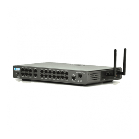
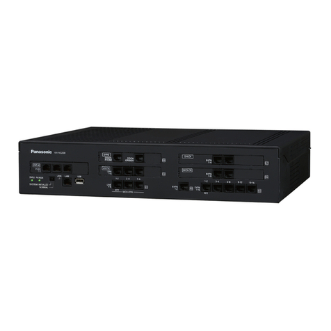
Matrix ETERNITY ME User manual

ETERNITY
Quick Start


ETERNITY
The IP-PBX with Seamless Mobility
and Universal Connectivity
Quick Start

Documentation Disclaimer
Matrix Comsec reserves the right to make changes in the design or components of
the product as engineering and manufacturing may warrant. Specifications are
subject to change without notice.
This is a general documentation for all models of the product. The product may not
support all the features and facilities described in the documentation.
Information in this documentation may change from time to time. Matrix Comsec
reserves the right to revise information in this publication for any reason without
prior notice. Matrix Comsec makes no warranties with respect to this documentation
and disclaims any implied warranties. While every precaution has been taken in the
preparation of this quick start, Matrix Comsec assumes no responsibility for errors
or omissions. Neither is any liability assumed for damages resulting from the use of
the information contained herein.
Neither Matrix Comsec nor its affiliates shall be liable to the purchaser of this
product or third parties for damages, losses, costs or expenses incurred by the
purchaser or third parties as a result of: accident, misuse or abuse of this product or
unauthorized modifications, repairs or alterations to this product or failure to strictly
comply with Matrix Comsec's operating and maintenance instructions.
Copyright
All rights reserved. No part of this quick start may be copied or reproduced in any
form or by any means without the prior written consent of Matrix Comsec.
Version 10
Release date: June 18, 2011

Table of Contents i
Contents
Introduction .................................................................................................... 1
Installing the ETERNITY ................................................................................ 3
Before you Start ................................................................................................ 3
Installing SLT, DKP and TWT Cards ................................................................. 6
Installing the BRI Card ...................................................................................... 7
Installing E&M Card ......................................................................................... 13
Installing Mobile Card ...................................................................................... 15
Installing VoIP Card ......................................................................................... 18
Connecting SIP Extensions ............................................................................. 22
Installing the T1E1PRI Card ............................................................................ 40
Installing VMS Card ......................................................................................... 45
Installing Door Phone Card ............................................................................. 47
Switching ON the system ................................................................................ 49
How to access Jeeves ..................................................................................... 50
Basic Configuration ..................................................................................... 53
‘Region’ ........................................................................................................... 55
Emergency Numbers ....................................................................................... 56
Enterprise Name ............................................................................................. 56
Time Zone-Automatic (Time Table), Day/Night Mode ..................................... 57
Flexible Numbers ............................................................................................ 57
DSS Consoles ................................................................................................. 58
CLIP ................................................................................................................ 60
Class of Service .............................................................................................. 60
Toll Control ...................................................................................................... 61
Trunk Access ................................................................................................... 61
LCR ................................................................................................................. 62
Trunk Landing ................................................................................................. 62
T1E1PRI .......................................................................................................... 64
Mobile Port ...................................................................................................... 66
BRI Port ........................................................................................................... 67
E&M Lines ....................................................................................................... 68
ii Table of Contents
VoIP Port ......................................................................................................... 69
SIP Trunks ....................................................................................................... 70
SIP Extensions ................................................................................................ 70
Logical Partition ............................................................................................... 72
Door Phone Card ............................................................................................ 73
VMS Card ........................................................................................................ 73
Appendix ....................................................................................................... 85
Universal Slots ................................................................................................ 85
Cable Diagrams for cards of ETERNITY-ME .................................................. 88
Cable Diagram for cards of ETERNITY-GE .................................................. 105
Cable Diagram for cards of ETERNITY-PE ................................................... 111

Matrix ETERNITY Quick Start 1
Introduction
Thank you for choosing the Matrix ETERNITY! This Quick Start is meant to help you
setup the ETERNITY and use the basic features.
For detailed description of the installation, advanced configuration and feature
description, please refer the ETERNITY System Manual provided to you on the CD-
ROM.
This Quick Start is applicable for firmware version V10.01 and later.

2 Matrix ETERNITY Quick Start

Matrix ETERNITY Quick Start 3
Installing the ETERNITY
Before you Start
Before you begin the installation of the ETERNITY ME/GE/PE, make sure that the
required telecom wiring has been done and you have the following items ready:
• A Main Distribution Frame (MDF)
• A suitable location to install the Main Distribution Frame and the ETERNITY
hardware. If you want to install the mobile card, make sure the place you select
has sufficient signal strength.
• Cables for trunk lines and extensions.
Terminate the trunk lines from the service provider network and the extension
lines from the field phones into the Main Distribution Frame.
• The Cards of ETERNITY, as required.
• One or more Single Line Telephone or Digital Key Phones, or IP Phones for
testing.
• Power supply.
The ETERNITY ME, GE and PE work with input voltages ranging between 100-
240VAC. Arrange for a separate power point and switch, close to the system.
Power supply for the system must be separate from other heavy electrical loads
like Air-conditioners, heaters, welding machines, electrical motors, etc.
• One or more active Two-wire trunk lines for test calls.
• A modem for the ISDN T1E1PRI line.
• An NT1 termination device for the ISDN BRI line.
• Appropriate cables and connectors to set up and test the Ethernet interface of
the ETERNITY and the LAN connection.

4 Matrix ETERNITY Quick Start
• A standalone PC or a PC connected in a LAN.
• A SIM card to test mobile network connectivity.
• A SIP Account to test VoIP connectivity.
• Make sure you have separate electrical earth and telecom earth for the safety of the product
and the persons handling it.
• Always wear a properly earthed (grounded) electrostatic discharge preventive belt or wrist
strap while handling the cards of the System.
• Use Primary Protection on trunk and long distance extension lines to protect the system from
lightning and electrical surges.
• Do not install the system near any source of water, corrosive fumes, and electromagnetic
noise such as radio equipment, heavy transformers, faulty electric chokes of tube-lights,
device having a faulty coil, to avoid electromagnetic effect.
Read the System Manual for safety precautions.
• Unpack the system.
• Make sure that your package contains all the below items. If any item is missing
or damaged, please contact the source from where you have purchased the
system.
Wall mounting nails
Mounting Template
MDF cable for Switch Card (provided with ETERNITY ME only)
Telephone Personality Guide
Matrix Logos
ETERNITY Platform
3 Pin AC Mains cable
CD containing Voice Messages, System Manual,
Quick Start and User Card.
Quick Start and
User Card
Support Card
Warranty Card
RJ-45 Cable

Matrix ETERNITY Quick Start 5
• Place the system at the location you have selected.
•If installing ETERNITY ME or GE,
• unscrew and remove the filler bracket of the slots you want to insert the
cards.
• insert the cards into the Universal Slots. Make sure the connectors on the
card and those on the motherboard on the backplane make perfect contact.
• press down the levers of the card mounting brackets and secure the card in
its slot with the screws provided.
•If installing ETERNITY PE,
• unscrew the top cover and keep the screws and the cover aside.
• select a Universal Slot to place the card and remove the screws on the
studs.
• seat the card on the slot such that the card connectors make perfect contact
with the connector pins on the CPU.
• secure the card on the slot by fixing the screws on the studs.
• replace and secure the cover after you have completed installation of all
cards and connecting the cables.
See “Appendix” for position of the Universal Slots in your model.

6 Matrix ETERNITY Quick Start
Installing SLT, DKP and TWT Cards
• Unpack the SLT, TWT, DKP cards. Remove the filler brackets of the universal
slots and insert the cards.
• Plug the MDF cables provided with each card into the connectors of the cards.
• Terminate the free ends of the MDF cables from the card connectors into the
Krone modules of the Main Distribution Frame. Refer the cable connections
given in the “Appendix” for terminating the cables into the Main Distribution
Frame.
• Connect Single Line Analog Telephone instruments to the SLT ports over the
MDF.
• Connect Digital Key phones, EON42, EON48 and their consoles DSS72 and
DSS16X4 to the DKP Ports over the MDF.
• Connect Two Wire Trunk (Analog Trunk) lines to the TWT ports over the MDF.

Matrix ETERNITY Quick Start 7
Installing the BRI Card
• Unpack the BRI card.
• Set the Orientation Type of the BRI Ports as Terminal (TE) or Network (NT)
mode as per your installation requirement.
In ETERNITY ME
• To set the Orientation Type of the BRI Port as either NT or TE, change the
position of the jumpers located on the main board of the card. Refer the tables
below for jumper positions for each BRI port. Default: All ports are set as TE.
Mode Jumper Position
BRI Port 1 BRI Port 2
J20 J21 J22 J23 J24 J25 J26 J27
NT BC BC BC BC BC BC BC BC
TE AB AB AB AB AB AB AB AB
Mode Jumper Position
BRI Port 3 BRI Port 4
J28 J29 J30 J31 J32 J33 J34 J35
NT BC BC BC BC BC BC BC BC
TE AB AB AB AB AB AB AB AB
Mode Jumper Position
BRI Port 5 BRI Port 6
J36 J37 J38 J39 J40 J41 J42 J43
NT BC BC BC BC BC BC BC BC
TE AB AB AB AB AB AB AB AB

8 Matrix ETERNITY Quick Start
In ETERNITY GE
• To set the BRI Ports of ETERNITY GE as NT or TE, refer the tables below to
change the position of the Jumpers on the main board of the BRI Card. Default:
all ports are set as TE.
Mode Jumper Position
BRI Port 7 BRI Port 8
J44 J45 J46 J47 J48 J49 J50 J51
NT BC BC BC BC BC BC BC BC
TE AB AB AB AB AB AB AB AB
Mode Jumper Position
BRI Port 1 BRI Port 2
J1 J2 J3 J4 J6 J7 J8 J9
NT BC BC BC BC BC BC BC BC
TE AB AB AB AB AB AB AB AB
Mode Jumper Position
BRI Port 3 BRI Port 4
J10 J16 J17 J18 J14 J15 J19 J20
NT BC BC BC BC BC BC BC BC
TE AB AB AB AB AB AB AB AB

Matrix ETERNITY Quick Start 9
In ETERNITY PE
• To set the BRI Ports of ETERNITY PE as TE or NT, refer the tables below to
change the position of the jumpers on the main board of the BRI Card. Default:
all ports are set as TE.
Common Instructions for installing the BRI card in ETERNITY ME, GE,
and PE
• A BRI Port can be configured in the TE/NT mode. Depending on the installation
and configuration scenario, Termination Resistance of 100should be inserted.
• When the BRI Port is configured as Network, NT mode, power may have to be
fed to the terminal equipment connected to the BRI port.
Inserting Termination Resistance on the BRI Port
• Termination Resistance should be inserted in the following cases
1. When the BRI port is configured in NT mode.
2. When the BRI port is configured in TE mode and connected in a Point-to-Point
configuration as shown in figure 1.
Figure 1:
Mode Jumper Position
BRI Port 1 BRI Port 2
J1 J2 J4 J5 J7 J8 J10 J11
NT BC BC BC BC BC BC BC BC
TE AB AB AB AB AB AB AB AB

10 Matrix ETERNITY Quick Start
3. When the BRI port is configured in TE mode and connected as the last
terminal on the S0 bus (Multi-point configuration) as shown in figure 2.
Figure 2:
• Termination need not be inserted in case 2 and 3 above, if the S0 bus itself
supports Termination resistors.
• Termination need not be inserted if the BRI port of ETERNITY (configured in TE
mode) is connected as any terminal other than the last terminal on the S0 bus
(in a Multi-point configuration).
• To set the 100termination on the BRI port set the Jumpers J3 and J4 located
on the BRI Module (daughter board) of the card as shown in the table.
Feeding Power to Terminal Equipment
• To feed power from ETERNITY to the terminal equipment connected to a BRI
port in the NT mode, change the position of the Jumpers J1 and J2 on the BRI
modules (daughter board) of the BRI Card as shown in the table.
Function Jumper Position
J3 J4
To insert 100termination (default position) AB AB
To remove 100termination BC BC
Function Jumper Position
J1 J2
To feed power on Tx and Rx wires (Phantom Power) AB AB
To feed power on separate pair of wires BC BC
No power to be fed to the terminal equipment (default position) Open Open
ISDN
Network
NT
BRI TE
ETERNITY
BRI Line
BRI TEBRI TE
Other ISDN
Equipment
Other ISDN
Equipment

Matrix ETERNITY Quick Start 11
The number of ISDN Terminals that can be connected on the BRI port configured in the NT mode
depends on the power consumed by the ISDN terminals.
From signaling point of view, up to 8 terminal equipment can be connected on the BRI port
configured in the NT mode. But the maximum power that can be fed to a single BRI port is 50mA.
So, connect ISDN Terminals to the BRI port according to the power consumed by them, which
together do not exceed 50mA.
• Insert the BRI card in any free Universal Slot and secure the card.
• Use the cable supplied for each connector on the BRI card to connect the BRI
Ports to the NT1 device supplied by your ISDN service provider. See the tables
below for configuration and pinout details.
Configuration of the U interface (RJ-45) at NT1
Configuration of the S/T interface (RJ-45) on NT1
Pin details of BRI Port in TE mode
Pin Number Pin Details
4Tx
5Rx
Pin Number Pin Details
3Rx1
4Tx1
5Tx2
6Rx2
Pin Number Signal Color
1-- Orange-White
2-- Orange
3TX-A Green-White
4RX_A Blue
5RX_B Blue-White

12 Matrix ETERNITY Quick Start
Pin details of BRI Port in NT Mode
This is a typical connection of a BRI Line to the ETERNITY ME BRI port in the TE
mode:
LED indication for BRI Ports
6TX_B Green
7VOUT- Brown-White
8VOUT+ Brown
Pin Number Signal Color
1-- Orange-White
2-- Orange
3RX-A Green-White
4TX_A Blue
5TX_B Blue-White
6RX_B Green
7VOUT- Brown-White
8VOUT+ Brown
Port Status LED Color LED Cadence
Port active Red Continuously ON
Port not active Green Continuously ON
Pin Number Signal Color

Matrix ETERNITY Quick Start 13
Installing E&M Card
• Unpack the E&M card.
• The E&M Card supports E&M Interface Type IV and Type V connection.
• To select the Interface Type you require, change the position of the jumpers on
the E&M module. See the table below for jumper position to set Interface Type.
• Select the Speech Interface—2-wire speech or 4-wire speech—as required, by
changing the jumper position on the E&M module. See the table below for
jumper positions.
• Select a universal slot for the E&M card and insert the card in the slot and
secure it.
• Connect the cables supplied with the E&M card into the connectors on the E&M
Card.
• Connect the free end of the cable into the E&M Ports of the other PBX/Router/
Tie Line equipment with appropriate crossing of the wires.
• For connecting the wires, refer the pinout details for each E&M Card Type and
for each E&M Type and Speech Interface Type given in the “Appendix”.
Function Jumper Position
J1 J2
Type IV E&M Interface (default position) AB AB
Type V E&M Interface BC BC
Function Jumper Position
J3 J4
4-wire speech interface AB AB
2-wire speech interface (default position) BC BC

14 Matrix ETERNITY Quick Start
LED indication for E&M Ports
Stage LED
Color LED Cadence
Initialization
At Power ON Red
L1 to L8 glow one after the other in a
sequence, ON 100ms -OFF.
L1 ON 100ms-OFF,
L2 100ms ON-OFF,
L3 100ms ON-OFF,
L4 100ms ON-OFF……L8 100ms ON-OFF
Green
L1 to L8 glow one after the other in a
sequence, ON 100ms -OFF.
L1 ON 100ms-OFF,
L2 100ms ON-OFF,
L3 100ms ON-OFF,
L4 100ms ON-OFF……L8 100ms ON-OFF
Standby (waiting to
be detected by
Master Card)
Green,
Orange L1 toggles Green ON 1 sec, Orange ON 1 sec
Normal (Port Event)
M-Wire High Green LED of the Port continuously ON
M-Wire Low LED of the Port continuously OFF
E-Wire High Red LED of the Port continuously ON
M-Wire Low LED of the Port continuously OFF
E-Wire and M-Wire
High Orange LED of the Port continuously ON
Errors
Controller RAM
failure
Orange All LEDs Toggle at 1 sec
External RAM failure Orange All LEDs Toggle at 2 sec
Eprom failure Orange All LEDs Toggle at 3 sec
Invalid Slot detected Orange All LEDs Toggle at 6 sec
This manual suits for next models
2
Table of contents
Other Matrix PBX manuals

Matrix
Matrix ETERNITY NE User manual

Matrix
Matrix Vision User guide

Matrix
Matrix ETERNITY User manual

Matrix
Matrix ETERNITY NE User manual

Matrix
Matrix Visionpro User guide

Matrix
Matrix ETERNITY NE User manual

Matrix
Matrix ETERNITY NE User guide

Matrix
Matrix ETERNITY Parts list manual

Matrix
Matrix Visionpro User manual

Matrix
Matrix PROTON 103 User manual
Popular PBX manuals by other brands

Siemens
Siemens SATURN IIE EPABX Installation test procedures

Switch Voice
Switch Voice BR4 user manual

Key System US
Key System US Atlas IIE KSX 32i installation manual

Panasonic
Panasonic KX-TDE100 Features guide

JING JIE
JING JIE UniPBX-2000 Administrative guide

Grandstream Networks
Grandstream Networks UCM6 series Service guide