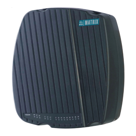
Matrix Visionpro User manual

VISIONPRO
Quick Start

VISIONPRO
The Digital PBX for Small Offices
Quick Start

Documentation Disclaimer
Matrix Comsec reserves the right to change, at any time, without prior notice, the product design,
specifications, components, as engineering and manufacturing may warrant.
This is a general documentation for all models/configurations of the product. The product may not
support some of the features/facilities described in this document.
While every reasonable effort has been made to ensure accuracy of content in this document,
Matrix Comsec assumes no responsibility for errors or omissions that may occur herein. No
liability is assumed for damages, costs, expenses resulting from unauthorized modifications or
repairs to the product; failure to use information or to comply with the installation, operation and
maintenance instructions contained in this document.
Copyright
All rights reserved. No part of this document may be copied or reproduced in any form or by any
means without the prior written consent of Matrix Comsec.
Version V1
Release date: October 4, 2019

Table of Contents i
Contents
Know Your VISIONPRO ................................................................................. 1
Overview ........................................................................................................... 1
Installing VISIONPRO .................................................................................... 3
Preparing for Installation ................................................................................... 3
Getting Started .................................................................................................. 3
Connecting VISIONPRO .................................................................................. 4
Power On VISIONPRO ..................................................................................... 6
Configuring VISIONPRO ................................................................................ 9
Test Calls ........................................................................................................ 14

Matrix VISIONPRO Quick Start 1
Know Your VISIONPRO
Thank you for choosing the Matrix VISIONPRO. Please read the instructions in this Quick Start
carefully to install and configure it.
This Quick Start is meant to help you install and configure the VISIONPRO quickly. For detailed
instructions on configuring the product and its feature description, refer to the System Manual.
To view or download the documents, scan the QR Code printed on the Product Label/Packaging
Label. You can also view or download the documentation from https://www.matrixtelesol.com/
product-manuals.html
For product registration and warranty related details, please visit http://www.matrixcomsec.com/
product-registration-form.html
Overview
Matrix VISIONPRO is an integrated digital SOHO (Small Office Home Office) PBX which caters to
the communication requirements of small businesses.
VISIONPRO series from Matrix offers the following variants,
• VISIONPRO 206 with 2 CO Trunk Ports (FXO Ports) and 6 SLT Ports (FXS Ports).
• VISIONPRO 308 with 3 CO Trunk Ports (FXO Ports) and 8 SLT Ports (FXS Ports).
• VISIONPRO 412 with 4 CO Trunk Ports (FXO Ports) and 12 SLT Ports (FXS Ports).

2 Matrix VISIONPRO Quick Start
This Quick Start is written with reference to the default configuration, VISIONPRO 308, unless
otherwise specified.
Ports and Connectors
LED
Port Description
Power Port To connect the external power adapter of 12V DC (input).
Earth To connect the telecom earth to the system.
CO To connect the CO trunk lines from PSTN.
SLT To connect station SLT phones, FAX machines.
RESET To reset the SE/SA Password to its default value.
LED Description
PWR To indicate system power ON/OFF condition.
STS To indicate the system status during various conditions.

Matrix VISIONPRO Quick Start 3
Installing VISIONPRO
Preparing for Installation
You must have the following:
• A suitable location to install VISIONPRO.
• Necessary telecom wiring in place, with wall jacks for station lines at the required locations.
• Standard, good quality, twisted pair telephone cables with 0.5 mm conductor diameter.
• A dedicated Power supply outlet close to the system.
• As many standard analog telephone instruments with CLI display to connect as SLT stations.
• A fax machine, if you want to connect one to the SLT Port of VISIONPRO.
• One or more active, analog trunk lines from the CO network, as required.
Well begun is half done; plan your hardware installation well.
• Do not install this product near an area where-
• it is exposed to direct sunlight, heat, excessive cold or humidity, dust, oil, corrosive
fumes.
• there is a water source (wash basin, tub, shower, pool, sprinkler etc.)
• there is source of electromagnetic noise such as radio equipment, heavy transformers,
faulty electric chokes of tube-lights, device having a faulty coil.
• Ensure proper electrical earth and telecom earth for the safety of the product and persons
handling it.
Getting Started
Unpack VISIONPRO and verify your package contents. In case any of the items is missing or
damaged, contact your Dealer/Distributor.

4 Matrix VISIONPRO Quick Start
Package Contents
The ideal sales package for VISIONPRO should contain the following items:
• One VISIONPRO Unit
• A 12V Power Adapter
• A Wall Mounting Template
• Two Screw Grips
• Two M7/30 Screws
You can view or download the documentation of the product by scanning the QR code printed on
the Product Label/Packaging Label.
Connecting VISIONPRO

Matrix VISIONPRO Quick Start 5
To connect the CO cables to the VISIONPRO,
• Use standard, good quality, twisted-wire pair telephone cables to connect the CO Ports of
VISIONPRO to the Trunk Lines from the CO (central office) network.
• Strip off about half a centimeter of the insulation off the wire ends of the CO cable.
• Using a blunt pin or a small flat screw driver, push back the levers of the connector.
• Insert the stripped ends of the two wires into the two openings of the connector, with one wire
in each opening.
• Ensure that both wires fit neatly into the opening.
• Release pressure on the levers. Both wires will be held in place by spring clamp action.
If you need to remove the wires,
• Push back the levers.
• Pull out the wires gently.
• Release pressure on the levers.
To connect the SLT cables to the VISIONPRO,
• Use standard twisted wire pair cables of good quality to connect the analog single line
telephone instruments to the SLT Ports of VISIONPRO.

6 Matrix VISIONPRO Quick Start
• Place the SLTs, fax machine at the desired locations. Connect the SLTs, Fax machine to the
wall jacks.
• Terminate one end of the cable on the wall jack to which the SLT, fax machine is connected.
• From the other end of the wire, strip off about half a centimeter of the insulation.
• Using a blunt pin or a small flat screw driver, push back the levers of the connector.
• Insert the stripped ends of the two wires into the two openings of the connector, with one wire
in each opening.
• Ensure that both wires fit neatly into the opening.
• Release pressure on the levers. Both wires will be held in place by spring clamp action.
If you need to remove the wires,
• Push back the levers.
• Pull out the wires gently.
• Release pressure on the levers.
Power On VISIONPRO
• Check the mains voltage at the power plug from where the power supply is to be fed to the
system.
• Make sure system’s earthing is proper.
• Plug in the power adapter of VISIONPRO into the power outlet. Ensure proper contacts.
Switch ON the system. Observe the reset cycle on the front panel of the system.
Reset Cycle
• As soon as you power ON the system, the PWR (Power) LED on the front panel starts
glowing. The STS (Status) LED starts glowing approximately 5 seconds after power ON.
Thereafter, the STS LED blinks in a cadence of 1sec ON and 1sec OFF.
• The system also feeds Dial Tone to the stations.
• Check for Dial Tone on the telephone instruments connected to the system.

Matrix VISIONPRO Quick Start 7
LED Indication
LED Status Meaning Cadence
PWR
(Power)
ON System Powered ON Continuous
OFF System Powered OFF
STS (System
Status)
Slow Blinking Health is Normal 1sec ON 1sec OFF
Fast Blinking AC Impedance test is running 500ms ON 500ms
OFF
Continuous ON/
Continuous OFF System fault

Matrix VISIONPRO Quick Start 9
Configuring VISIONPRO
All parameters of VISIONPRO are configured by dialing the relevant command strings from a
station phone connected to the system.
Phone Wizard only allows programming of the basic parameters. For detailed programming, refer
the VISIONPRO System Manual.
Follow the instructions given below to configure the system using the Phone Wizard from the SE
mode.
To enter the Phone Wizard programming mode,
•Dial1#98-SE Password.
Where,
Default SE Password is 1234.
Date and Time
To Set Current Date,
•Dial27-Date-Month-Year-Day
Where,
Date is from 01 to 31
Month is from 01 to12
Year is from 00 to 99 (here, base year is '2000'. Enter '07' for year '2007')
Day is from 1 to 7 where, 1 = Sunday.
To Set Current Time,
•Dial28-Hour-Minute
Where,
Hour is from 00 to 23.
Minute is from 00 to 59.
Time has three parameters: Hour, Minute and Second. However, the above command
has only two parameters. The third parameter, Seconds will be set as '00' whenever new
time is programmed.

10 Matrix VISIONPRO Quick Start
SE and SA Password
To Set New SE Password,
•Dial291-New SE Password
Where,
SE Password is a 4 digit number string. Valid digits are from 0-9. SE password must be
strictly 4 digits long.
To Set New SA Password,
•Dial292-New SA Password
Where,
SA Password is a 4 digit number string. Valid digits are from 0-9. SA password must be
strictly 4 digits long.
Class of Service (CoS)
To assign to individual stations,
•Dial31-Ext-Day CoS Group-Night CoS Group
To assign to all stations,
•Dial31-*-Day CoS Group-Night CoS Group
Where,
Ext is the flexible number of the station. Flexible number can be of 1,2,3 or 4 digits.
Day CoS group is from 0 to 7
Night CoS Group is from 0 to 7
Toll Control
To assign to individual stations,
•Dial32-Ext-Day AL/DL List-Night AL/DL List
To assign to all stations,
•Dial32-*-Day AL/DL List-Night AL/DL List
Where,
Ext is the flexible number of the station. Flexible number can be of 1,2,3 or 4 digits.
Allowed List (AL) is from 0 to 7.
Denied List (DL) is from 0 to 7.
Clear All the Features
To clear all features for a station,
•Dial343-Ext
Where,

Matrix VISIONPRO Quick Start 11
Ext is the flexible number of a station. Flexible number can be of 1,2,3 or 4 digits.
Flash Timer for station
To assign to individual stations,
•Dial36-Ext-Flash Timer Count
To assign to all stations,
•Dial36-*-Flash Timer Count
Where,
Ext is the flexible number of a station. Flexible number can be of 1,2,3 or 4 digits.
Flash Timer Count is from 1 to 9 where Count 1 implies to 70-100 ms. For example, to set
Flash timer value as 101-600 ms, dial Flash Timer Count as 6.
Flexible Number
To assign to individual stations,
•Dial37-Software Port No-Flexible Number-#*
To load the default Flexible Numbers,
•Dial 37-*-0
Where,
Software Port No is from 00 to 07.
Flexible Number can be any 1,2,3 or 4 digit number strings. Terminate the command using
‘#*’ if the flexible number consists of less than four digits. Two stations can not have the
same flexible number.
Operator Station
To assign a particular station as the operator,
•Dial391-Ext
Where,
Ext is the flexible number of a station. Flexible number can be a 1, 2, 3 or 4 digit number
string.
Trunk Parameters
To enable/disable a trunk and assign it a dial type,
•Dial41-Trunk-Enable/Disable Flag-Dial Type Flag
To set the enable/disable flag and the dial type for all trunks at once,
•Dial41-*-Enable/Disable Flag-Dial Type Flag
Where,

12 Matrix VISIONPRO Quick Start
Trunk is from 0 to 2.
Enable/Disable flag codes are,
0 for Disable
1 for Enable
Dial type can be either Pulse or Tone where corresponding flag codes are,
0 for Pulse
1 for Tone
DID
To configure a trunk for DID calls,
•Dial43-Trunk-Day Code-Night Code
Where,
Trunk is from 0 to 2
Day Code/Night Code flags are,
0 for Disable
1 for Enable
DOSA
To configure a trunk for DOSA calls,
•Dial45-Trunk-Day Code-Night Code
Where,
Trunk is from 0 to 2.
Day Code/Night Code flags are,
0 for Disable
1 for Enable
Trunk Landing Destination for Day Mode
To assign the Trunk Landing Destination for Day Mode,
•Dial47-Trunk-Ext1-Ext2-Ext3-Ext4
To assign the Trunk Landing Destination for Day Mode for all trunks at once,
•Dial47-*-Ext1-Ext2-Ext3-Ext4
Where,
Trunk is from 0 to 2.
Ext1 to Ext4 are the flexible numbers of destination stations. Flexible number can be of 1,2,3
or 4 digits. Maximum four destinations can be programmed for a single trunk.

Matrix VISIONPRO Quick Start 13
Trunk Landing Destination for Night Mode
To assign the Trunk Landing Destination for Night Mode,
•Dial48-Trunk-Ext1-Ext2-Ext3-Ext4
To assign the Trunk Landing Destination for Night Mode for all trunks at once,
•Dial48-*-Ext1-Ext2-Ext3-Ext4
Where,
Trunk is from 0 to 2.
Ext1 to Ext4 are the flexible numbers of destination stations. Flexible number can be of 1,2,3
or 4 digits. Maximum four destinations can be programmed for a single trunk.
Hunt Timer
Hunt Timer is defined as the time for which a station rings when a trunk call lands on that station.
It is similar to the 'Ring Timer'. On expiry of the Hunt Timer, the next station of the Station Group
assigned to the trunk will start ringing.
To configure the Hunt Timer,
•Dial212-Timer
Where,
Timer is from 01-99 seconds.
Hunting Scheme
To configure the Day and Night Hunting scheme for a trunk,
•Dial46-Trunk-Day Hunting Scheme-Night Hunting Scheme
To configure for all trunks at once,
•Dial46-*-Day Hunting Scheme-Night Hunting Scheme
Where,
Trunk is from 0 to 2.
Hunting Scheme is,
0 for Hunting Off
1 for Round Robin
2 for Delayed Simultaneous
3 for Immediate Simultaneous
To exit the Phone Wizard programming mode,
•Dial0.
You can exit the programming mode by dialing this command at any time.

14 Matrix VISIONPRO Quick Start
Test Calls
Making an Internal Call
• Lift the handset.
• Dial the desired station’s flexible number. Default flexible numbers are 21, 22, 23, 24, 25, 26,
27 and 28.
• The called station rings. You get the Ring Back Tone.
• Speech is established when the called station answers.
Making an External Call
• Lift the handset.
• Dial a Trunk Access Code (TAC). Default TACs are 0, 5, 61, 62, 63.
• Dial the external number.
Answering Calls
When a call is placed on your station from an internal caller, then your phone rings as -
Trin................ Trin.................... This is called single ring.
If the caller is an external caller, and the trunk call lands on your station, then your phone rings as
- Trin....Trin...............Trin.....Trin............... This is called double ring.
The ring type differentiates an internal caller from an external caller.

Version 1, October 2019
MATRIX COMSEC
Head Office
394-GIDC, Makarpura, Vadodara - 390010, India.
Ph: (+91)1800-258-7747
E-mail: Customer.Care@MatrixComSec.com
www.MatrixTeleSol.com
Other manuals for Visionpro
1
Table of contents
Other Matrix PBX manuals

Matrix
Matrix ETERNITY NE User guide

Matrix
Matrix ETERNITY NE User manual
Matrix
Matrix ETERNITY User manual
Matrix
Matrix ETERNITY NE User manual

Matrix
Matrix Vision User guide

Matrix
Matrix PROTON 103 User manual

Matrix
Matrix Visionpro User guide

Matrix
Matrix ETERNITY Parts list manual

Matrix
Matrix ETERNITY NE User manual

Matrix
Matrix ETERNITY ME User manual
Popular PBX manuals by other brands
Orchid Telecom
Orchid Telecom PBX 308 System administration guide

LG-Nortel
LG-Nortel IP LDK-20 Programming manual

TeleSynergy
TeleSynergy AbovEdge SS-7010 Quick installation guide

Fiberme
Fiberme FCM630A Quick installation guide

Panasonic
Panasonic KX-TDE100 operating manual

MCK
MCK EXTender 3000 Quick installation guide