manuals.online logo
Brands
  1. Home
  2. •
  3. Brands
  4. •
  5. Max-Air Systems
  6. •
  7. Protection Device
  8. •
  9. Max-Air Systems ME E 008-013 Series Manual

Max-Air Systems ME E 008-013 Series Manual

Rev: 10/10/22
Website
Max-Air Technology, Inc. • 114 Resource Drive • Wentzville, MO 63385 • United States of America
Tel +1.636.272.4934 • Toll Free 888.842.9998 • Fax 636.272.4937 • www.maxairtech.com • [email protected]
1
File Name: Max-Air_IOM_ME_E008~013_LVHV_Mod_converted.pdf
ME E 008~013 Series LV/HV | Mod
Installation, Operation and Maintenance Instructions
Throughout the installation phases and operation of this equipment,
safety procedures take precedence over all other activities. As a minimum:
1. Read and follow all instructions in this IOM.
2. Risk of electric shock! All wiring must be in accordance with applicable local
codes, regulations and the NEC. Be aware that there may be hazardous voltages
present which can shock, burn, or possibly cause permanent injury or even death.
3. Before handling electrical connections, disconnect power feeds. There may
be multiple power feeds connected to this unit. Check all terminal connections
carefully when servicing the actuator.
4. This is a mechanical gear train system with high torque outputs. Connected
mechanical linkages can and will cause personal injury if the user encounters a
pinch-point during movement.
Safety First!
Handling & Storage:
1. This device is an electrically powered mechanical transmission
system. It is comprised of a DC motor, an asynchronous AC motor,
or a polyphase AC motor, logic control PC boards, various discrete
electronic components and electrical storage devices, all of which
are susceptible to damage from high humidity environments. For this
reason, this device must be protected from direct contact with water
and/or high humidity storage environments.
2. Protect the device from physical damage while awaiting the
completion of installation processes.
3. If this product is installed in water valve systems and remains
unpowered during construction phases, condensate will accumulate
and possibly damage the product. This product MUST be powered up
at all times once it is installed in active piping systems.
Installation:
1. Conrm correct voltage and control before wiring and powering up
this actuator.
2. This device has been permanently lubricated at time of assembly.
Maintain proper lubrication level by ensuring the actuator is mounted
with the top cover at or above horizontal. This device is NOT designed
to mount with the top cover below horizontal.
3. Use approved conduit entry components to protect the interior of
the unit from ingress of foreign materials (including water). Utilize drip
loops to prevent conduit condensate from accumulating and entering
the actuator throught the EMT port(s).
4. Refer to the dimensional diagram (rear pages) for proper clearance
on all sides as well as the top cover clearance requirements. Determine
proper access space for the manual override system.
5. When mounting this device to a valve or damper, ensure the mating
between the valve stem (or coupling) is NOT deeper than the socket
depth in the bottom of the actuator. Use the proper length and thread
bolts for mounting. (See dimensional diagram).
6. Ensure the actuator is concentrically mounted to the valve stem.
Non-concentricity causes premature actuator or valve-stem seal
failure, or actuator stalling due to high-torque during travel.
7. Use properly sized power supplies and wire gauge over distance to
prevent actuator failure from stalling and overheating.
8. Refer to the wiring diagram sheet (folded, inserted under the
actuator cover) for wiring connections. You can also scan the QR code
above and navigate to the Max-Air website to obtain a full-size wiring
diagram.
9. Do NOT parallel wire multiple on-o actuators to the same eld
control terminals. This WILL cause unexpected movement of the
actuator(s), overheating and premature failure.
10. After installation and testing, do NOT operate the actuator with any
covers removed.
11. It is recommended to operate the actuator for at least ten minutes
once per month, as a minimum.
12. The internal heater is to be used in ALL applications.
13. Mechanical travel stops are factory calibrated for 90 degree operation.
These stops are NOT designed to adjust mechanical rotation by more
than +/- 3 degrees.
14. Mechanical stops CANNOT be used to limit travel electrically. Stalling
this unit will damage the drive motor and control PCB's.
ME C 004 Series LV/HV | Mod
(con't) Installation, Operation and Maintenance Instructions
Rev: 10/10/22
Website
Max-Air Technology, Inc. • 114 Resource Drive • Wentzville, MO 63385 • United States of America
Tel +1.636.272.4934 • Toll Free 888.842.9998 • Fax 636.272.4937 • www.maxairtech.com • [email protected]
2
File Name: Max-Air_IOM_ME_E008~013_LVHV_Mod_converted.pdf
The purpose of the mechanical stops are for limiting the manual
override only!! Serious damage to the actuator will result if the
motor is allowed to drive the gear train into the mechanical stops!
This actuator has been factory calibrated to operate between 0° and
90°. Most quarter-turn products will not require recalibration of these
settings.
Default Operating Mode:
This actuator leaves the factory with the following default settings:
Input signal is 4-20mA, response is direct acting (20mA = full CCW - OPEN),
feedback is 4-20mA, Unit is set for 90° travel, and sensitivity is set at "3"
(0.5% full scale).
This manual is written for the proportional control actuators with DC drive
motors. (This is NOT the same as the power supply feeding the actuator).
This actuator must be calibrated prior to putting into service.
If this is a
stand-alone actuator, follow all the steps given here after mounting the
actuator to the driven device (valve, damper or other). If this actuator has
been factory mounted to the driven device, more than likely it has already
gone thru calibration and nothing further needs to be done.
1. The actuator normally ships in the full CW (Closed) position. This can
be veried by observing the location of the punched dimple in the main
output drive on the bottom of the actuator. The dimple should be pointing
towards the "0" in the lower housing casting. Use the handwheel to
reposition the output gear if the position is incorrect. (Fig 1)
2.
Do NOT apply power at this time.
3. Use a 17mm box wrench and a 5mm hex key to back out BOTH mechanical
stops. (Fig 2 & 3). Once the lock nut is loose, back out the stop screws by
3~4 full turns. Leave everything loose.
4.
Set the CW end of travel cam
.
a. Rotate the handwheel (CCW) to drive the actuator out to about 15~20
degrees open, then back to the desired CLOSED (CW) position. If you have
driven the device too far, you must drive back out to 10~15 degrees before
again approaching the correct CW stop. You cannot set the stop when
driving in a CCW direction due to cam dwell angle.
b. Using a 2.5mm hex key on CAM #2 (Fig 4), loosen the cam set screw and
rotate the cam CCW by pushing the hex key to the RIGHT a few degrees.
Lightly snug up on the set screw until resistance is felt against the cam
shaft. Pull the hex key to the LEFT SLOWLY until you hear a "click" from the
associated (#2) cam switch and snug up on the cam setscrew. Do not move
the actuator. No need to overtighten the cam setscrew.
5.
Set the CW auxiliary switch.
a. Using the 2.5mm hex key on CAM #4 (Fig 5) loosen the cam set screw and
rotate the cam CCW by pushing the hex key to the RIGHT a few degrees.
Lightly snug up on the set screw until resistance is felt against the cam
shaft. Pull the hex key to the LEFT SLOWLY until you hear a "click" from the
associated (#4) cam switch and continue a few more degrees in the same
direction. (This assures the AUX switch trips before the actuator reaches its
end of travel. Snug up on the cam setscrew.
6.
Set the CCW end of travel cam
.
a. Rotate the handwheel (CCW) to drive the actuator out to full OPEN
(CCW) to check for any obstructions in operation. Rotate the handwheel
back to about 75~80 degrees open, and then back to the desired OPEN
(CCW) position. If you have driven the device too far, you must drive back
out to 75~80 degrees before again approaching the correct CCW stop. You
cannot set the stop when driving in a CW direction due to cam dwell angle.
b. Using a 2.5mm hex key on CAM #1 (Fig 6), loosen the cam set screw
and rotate the cam CW by pushing the hex key to the LEFT a few degrees.
Lightly snug up on the set screw until resistance is felt against the cam
ME E 008~013 Series LV/HV | Mod
(con't) Installation, Operation and Maintenance Instructions
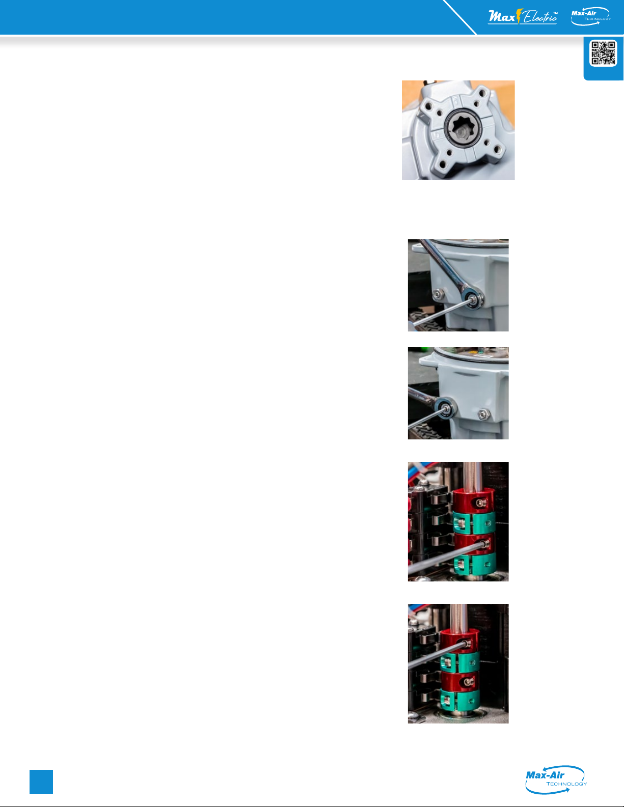
Fig 1 - Bottom view of actuator showing the “0”
mark (Closed [CW] position), the “1” mark (Open
[CCW] position), and the dimple reference. The
actuator is shipped from the factory in its fully
CLOSED position.
Fig 3 - Left side (CCW) mechanical stop
Fig 2 - Right side (CW) mechanical stop
Fig 4 - CW EOT Cam adjustment
Fig 5 - CW AUX Cam adjustment
ME C 004 Series LV/HV | Mod
(con't) Installation, Operation and Maintenance Instructions
Rev: 10/10/22
Website
Max-Air Technology, Inc. • 114 Resource Drive • Wentzville, MO 63385 • United States of America
Tel +1.636.272.4934 • Toll Free 888.842.9998 • Fax 636.272.4937 • www.maxairtech.com • [email protected]
3
File Name: Max-Air_IOM_ME_E008~013_LVHV_Mod_converted.pdf
shaft. Pull the hex key to the RIGHT SLOWLY until you hear a "click" from
the associated (#1) cam switch and snug up on the cam setscrew. Do not
move the actuator. No need to overtighten the cam setscrew.
5.
Set the CCW auxiliary switch.
a. Using the 2.5mm hex key on CAM #3 (Fig 7) loosen the cam set
screw and rotate the cam CCW by pushing the hex key to the RIGHT
a few degrees. Lightly snug up on the set screw until resistance is felt
against the cam shaft. Pull the hex key to the LEFT SLOWLY until you hear
a "click" from the associated (#3) cam switch and continue a few more
degrees in the same direction. (This assures the AUX switch trips before
the actuator reaches its end of travel. Snug up on the cam setscrew.
6. Set the signal processing for the actuator. (ref Fig 8)
Use the table below to set the eight (8) DIP switches to establish signal
type, response and fault modes of operation.
DIP S1 S2 S3 S4 S5 S6 S7 S8
MODE INPUT FEEDBACK RESPONSE LOSS OF SIGNAL
4-20MA ON OFF OFF ON OFF OFF = DIR
CW OFF ON
CCW ON OFF
LAST ON ON
2-10VDC OFF ON ON OFF ON ON = REV
CW ON OFF
CCW OFF ON
LAST ON ON
7. Set the signal response. (ref Fig 8) Remove power. Manually position the
actuator to about 50% open, and then re-apply power. The actuator will travel
in a CW direction until it reaches its full CW end of travel position (set by cam#2
in step 4 above). Press and hold the "SET" button on the logic PCB for 2 seconds.
The PCB will enter local setting mode. LED9 will illuminate.
- Press and hold the "UP" button until the actuator reaches it full OPEN (CCW)
position (LED 2 ON), and generate a 20mA signal. Press the "MODE" button for 2
seconds to set the full CCW position.
- Press and hold the "DN" button until the actuator reaches it full CLOSED (CW)
position (LED 1 ON), and generate a 4mA signal. Press the "MODE" button for 2
seconds to set the full CW position.
- Check the feedback (4mA) and adjust VR2 if necessary. Turning VR2 CW
decreases the feedback value. Turning VR2 CCW increases the feedback value.
- The 20mA feedback value is generated by the microprocessor and is not
adjustable.
- Press the "SET" button to SAVE these settings.
8. After setting the analog response, check the operation of the actuator in
response to your input signals to make sure operation is as intended. After
verication that all settings are correct, generate a 4mA input signal to drive
the actuator to its full CW position, and wait for it to stop.
9. Set the CW mechanical stop. (Fig 9) Use the 5mm hex key on the RIGHT side
stop screw and turn it clockwise until it bottoms out against the internal stop
boss on the nal output drive. Turn the hex key ONE turn CCW, then use the
17mm box wrench to lock the stop screw in positon. Do not tighten the stop
screw so hard as to crush the sealing washer.
10. Generate a 20mA input signal to drive the actuator to its full CCW position,
and wait for it to stop.
11. Set the CCW mechanical stop. (Fig 10) Use the 5mm hex key on the LEFT
side stop screw and turn it clockwise until it bottoms out against the internal
stop boss on the nal output drive. Turn the hex key ONE turn CCW, then use
the 17mm box wrench to lock the stop screw in positon. Do not tighten the stop
screw so hard as to crush the sealing washer.
When the actuator reaches its end of travel electrically, you should be able
to rotate the handwheel at least 1/2 or more turns before you reach the
mechanical stop.This is true for both ends of travel. If the handwheel is "locked",
the mechanical stops have been set incorrectly and must be reset. Any time the
EOT cams need to be moved, the mechanical stops MUST be reset.
This completes the calibration of the actuator.
LED 9
ME E 008~013 Series LV/HV | Mod
(con't) Installation, Operation and Maintenance Instructions
Fig 6 - CCW EOT Cam adjustment
Fig 7 - CCW AUX Cam adjustment
DIP Switch setting
feedback calibration
status LEDs
4 button programming
Fig 8 - Analog Settings
Fig 9 - Right side (CW)
mechanical stop
Fig 10 - Left side (CCW)
mechanical stop
ME C 004 Series LV/HV | Mod
(con't) Installation, Operation and Maintenance Instructions
Rev: 10/10/22
Website
Max-Air Technology, Inc. • 114 Resource Drive • Wentzville, MO 63385 • United States of America
Tel +1.636.272.4934 • Toll Free 888.842.9998 • Fax 636.272.4937 • www.maxairtech.com • [email protected]
4
File Name: Max-Air_IOM_ME_E008~013_LVHV_Mod_converted.pdf
ME E 008~013 Series LV/HV | Mod
(con't) Installation, Operation and Maintenance Instructions
Specifications ME E008 ME E013
Supply Torque Output (in-lb / Nm) 800 in-lb / 90Nm 1335 in-lb / 150Nm
12V
Starting Current - DC Amps 12.0A 8.0A
Running Current - DC Amps 4.5A 4.6A
Speed (90°) @DC, seconds @ rated load 15 sec 24 sec
Motor, Voltage, Type, Class 12VDC 2-Pole Brush, Class F 12VDC 2-Pole Brush, Class F
Motor Power 40W 40W
Duty Cycle 100% (EN 60034) / Class A/B/C (ISO 22153)
24V
Starting Current - DC Amps 10.0A 10.0A
Running Current - DC Amps 2.8A 2.6A
Speed (90°) @DC, seconds @ rated load 18 sec 27 sec
Motor, Voltage, Type, Class 24VDC 2-Pole Brush, Class F 24VDC 2-Pole Brush, Class F
Motor Power 40W 40W
Duty Cycle 100% (EN 60034) / Class A/B/C (ISO 22153)
120V
Starting Current - AC Amps 3.0A 3.0A
Running Current - AC Amps 1.2A 1.2A
Speed (90°) @60Hz, seconds @ rated load 17 sec 26 sec
Motor, Voltage, Type, Class 120VAC Split-Phase Cap Run TENV Class F 120VAC Split-Phase Cap Run TENV Class F
Motor Power 40W 40W
Duty Cycle 100% (EN 60034) / Class A/B/C (ISO 22153)
230V
Starting Current - AC Amps 2.0A 2.0A
Running Current - AC Amps 0.6A 0.6A
Speed (90°) @60Hz, seconds @ rated load 17 sec 26 sec
Motor, Voltage, Type, Class 230VAC Split-Phase Cap Run TENV Class F 120VAC Split-Phase Cap Run TENV Class F
Motor Power 40W 40W
Duty Cycle 100% (EN 60034) / Class A/B/C (ISO 22153)
ALL
Environmental Rating NEMA 4/4X & IP67
Electrical Entry 3/4'' EMT x 2
Control Open/Close, Modulating, 2 Position, 3 Position
Auxiliary Switch - End of Travel (2) Form C Volt-Free, Rated 10A @ 250vac, 5A @ 30VDC
Ambient Operating Range -22°F~+149°F (-30°C~+65°C)
Humidity Range 0-95% RH
Altitude Limit 9850 ft / 3000 m
Weight (kg / lbs) 11 kg / 24.2 lbs
* All Amperage and speed specications based on Open/Close Standard Duty motors @ 40°C ambient.
** Refer to 3 phase data sheets for 3 phase power
102
4.012
231
9.077
[186]
7.315
267
10.524
30
1.181
[268]
10.551
TS
45°
22mm DSQ
BCD
102 mm
4.016 in
M10*1.5P
24mm DEPTH
4 POSITIONS
(ISO 5211 F10)
BCD
70 mm
2.756 in
M8*1.25P
20mm DEPTH
4 POSITIONS
(ISO 5211 F07)
85
3.346
[121]
4.764
123
4.836
3/4" NPT (2)
CONDUIT ENTRIES
COVER REMOVAL CLEARANCE
[200]
7.874
DIMENSIONS IN:
[mm]
in
D
C
B
A
A
B
C
D
1
2
3
4
5
6
7
8
8
7
6
5
4
3
2
1
THE INFORMATION CONTAINED IN THIS
DRAWING IS THE SOLE PROPERTY OF
MAX-AIR TECHNOLOGY, INC. ANY
REPRODUCTION IN PART OR AS A WHOLE
WITHOUT THE WRITTEN PERMISSION OF
MAX-AIR TECHNOLOGY, INC., IS
PROHIBITED.
PROPRIETARY AND CONFIDENTIAL
DRAWN
CHECKED
ENG APPR.
MFG APPR.
DATE
NAME
TITLE:
SIZE
B
REV
WEIGHT:
SCALE: 1:5
0
FDMVF
3/31/22
ELECTRIC ACTUATOR
DRAWING
SHEET 1
/1
ME E008
DWG. NO.
Max-Air Technology, Inc.
114 Resource Dr.
Wentzville, MO 63385
(888) 842-9998
www.maxairtech.com
Dimensional Drawing

Other Max-Air Systems Protection Device manuals

Max-Air Systems ME G Series Manual

Max-Air Systems

Max-Air Systems ME G Series Manual

Max-Air Systems CAPR Series User manual

Max-Air Systems

Max-Air Systems CAPR Series User manual

Popular Protection Device manuals by other brands

SOMFY J4 io Short installation guide

SOMFY

SOMFY J4 io Short installation guide

Ultrasonic SonicPRO installation manual

Ultrasonic

Ultrasonic SonicPRO installation manual

Guardian LINGO Quick start user guide

Guardian

Guardian LINGO Quick start user guide

Miller 216WLS User instruction manual

Miller

Miller 216WLS User instruction manual

Compliant Technologies E-Band user manual

Compliant Technologies

Compliant Technologies E-Band user manual

nvent ERICO System 3000 Installation, operation and maintenance manual

nvent

nvent ERICO System 3000 Installation, operation and maintenance manual

Belkin P74976UKAP41000EA3M user manual

Belkin

Belkin P74976UKAP41000EA3M user manual

Daniamant LJ2 Installation and maintenance instructions

Daniamant

Daniamant LJ2 Installation and maintenance instructions

SATA Vision 2000 operating instructions

SATA

SATA Vision 2000 operating instructions

OUTSTEEL VENITIAN installation instructions

OUTSTEEL

OUTSTEEL VENITIAN installation instructions

GE UR F35 Series instruction manual

GE

GE UR F35 Series instruction manual

ABB ret650 Product guide

ABB

ABB ret650 Product guide

Novus NVS-021CB user manual

Novus

Novus NVS-021CB user manual

Cardin Elettronica CDR Series manual

Cardin Elettronica

Cardin Elettronica CDR Series manual

ABB Relion 670 series Applications manual

ABB

ABB Relion 670 series Applications manual

Protect FOQUS installation manual

Protect

Protect FOQUS installation manual

HEPACART Classic HC55U18.ETL Maintenance manual

HEPACART

HEPACART Classic HC55U18.ETL Maintenance manual

Pizzato Elettrica CS MP208M0 installation instructions

Pizzato Elettrica

Pizzato Elettrica CS MP208M0 installation instructions

manuals.online logo
manuals.online logoBrands
  • About & Mission
  • Contact us
  • Privacy Policy
  • Terms and Conditions

Copyright 2025 Manuals.Online. All Rights Reserved.