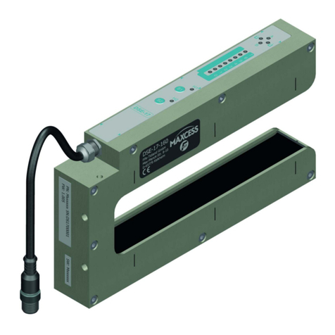
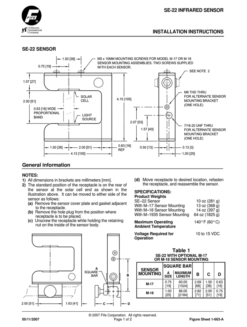
Maxcess FIFE DST-1 User manual

DST-1 Web Guiding Sensor
with Operator Interface
User Manual
EN
MI 2-311 1 B
FIFE GUIDING SOLUTIONS

CONTENTS
www.maxcessintl.com
DST-1
MI 2-311 1 B
Page 2 of 48
1.0 INTRODUCTION 5
1.1 About these operating instructions ................................................................. 5
1.2 Product overview............................................................................................. 6
1.3 Model number ................................................................................................ 6
1.4 Serial number.................................................................................................. 6
1.5 DST-1 components......................................................................................... 7
1.6 Ordering information ...................................................................................... 7
2.0 SAFETY 8
2.1 Instructions for use......................................................................................... 8
2.2 Symbols used.................................................................................................. 8
2.3 Basic safety information.................................................................................. 9
3.0 INSTALLATION 11
3.1 Product dimensions ...................................................................................... 11
3.2 Mounting the DST-1 operator interface ........................................................ 12
3.2.1 Wall mount ........................................................................................ 12
3.2.2 Panel mount ...................................................................................... 13
3.2.3 DST-1 mounting bracket assembly ................................................... 14
3.3 Electrical ....................................................................................................... 15
3.4 Wiring diagrams............................................................................................ 15
3.5 Analog outputs ............................................................................................. 16
3.5.1 DST-1 Analog output 1 and 2 ........................................................... 16
3.6 Optical sensor installation ............................................................................ 17
3.6.1 Optical sensor guidelines for installation .......................................... 17
3.6.2 Sensor placement guidelines ............................................................. 18
4.0 DST-1 PASSWORD SECURITY 19
4.1 Overview ....................................................................................................... 19
4.2 Set up password security (first time use)...................................................... 20
4.3 Identifying security status............................................................................. 22
4.4 Change password protection settings ........................................................... 22
4.5 Change password or password type.............................................................. 23
5.0 DST-1 OPERATOR INTERFACE MENU STRUCTURE 24
6.0 SENSOR OPERATING PARAMETERS 26
6.1 Global parameter group ................................................................................ 27
6.2 Manual setup parameters.............................................................................. 29
6.2.1 Camera parameters ........................................................................... 29
6.3 Signal function types .................................................................................... 30
6.4.1 Edge/Line detection functions........................................................... 32
6.4.2 ROI definition and configuration ....................................................... 33
6.4.3 Using DST-1 OI touch screen to set ROI ............................................ 34
AUTOMATIC SETUP PROCEDURE 35
CONTENTS
www.maxcessintl.com
DST-1
MI 2-311 1 B
Page 3 of 48
MANUAL SETUP PROCEDURE 37
8.1 Manual setup procedure steps ...................................................................... 39
9.0 SENSOR MAINTENANCE 40
9.1 Backup and restore device settings ............................................................... 40
9.1.1 Save device settings .......................................................................... 40
9.2 Device restore ............................................................................................... 41
9.2.1 Restore device settings...................................................................... 41
9.3 Firmware update ........................................................................................... 42
9.4 Replacing DST-1 components....................................................................... 43
9.4.1 Replacing the sensing element .......................................................... 43
9.4.2 Replacing the operator interface........................................................ 43
10.0 DEVICE RECOVERY OPTIONS 44
11.0 TROUBLESHOOTING 45
11.1 Fault diagnostics and rectification............................................................. 45
12.0 SPECIFICATIONS 46
13.0 SERVICE 47

CONTENTS
www.maxcessintl.com
DST-1
MI 2-311 1 B
Page 4 of 48
FIGURES
Figure 1. Component identification........................................................................................ 7
Figure 2. Dimensions: DST-1 sensing element and operator interface................................ 11
Figure 3. Cable and USB connections ................................................................................... 11
Figure 4. Operator interface wall mount installation ............................................................ 12
Figure 5. Operator interface panel mount installation .......................................................... 13
Figure 6. DST-1 mounting bracket assembly ....................................................................... 14
Figure 7. DST-1 to OI connections ....................................................................................... 15
Figure 8. Typical output wiring schematic............................................................................ 16
Figure 9. Sensor element practical FOV ................................................................................ 17
Figure 10. DST-1 sensor optical center location .................................................................. 18
Figure 11. DST-1 recommended sensor to web distance ..................................................... 18
Figure 12. DST-1 sensing element position examples ......................................................... 18
Figure 13. DST-1 Sensor internal signal processing flow order............................................ 26
Figure 14. DST-1 Sensor system elements........................................................................... 26
Figure 15. Signal parameter logic......................................................................................... 30
Figure 16. Signal function types........................................................................................... 30
Figure 17. Edge/line detection functions ............................................................................. 32
Figure 18. ROI function icons............................................................................................... 33
Figure 19. Signal data and manual setup flow directions ..................................................... 37
TABLES
Table 1. DST-1 Sensor optical setup guidelines ................................................................... 17
Table 2. Factory default job configuration settings .............................................................. 38

INTRODUCTION
www.maxcessintl.com
DST-1
MI 2-311 1 B
Page 5 of 48
1.0 Introduction
1.1 About these operating instructions
All of the information herein is the exclusive proprietary
property of Maxcess International, and is disclosed with the
understanding that it will be retained in confidence and will
neither be duplicated nor copied in whole or in part nor be
used for any purpose other than for which disclosed.
Copyright 2019, all rights reserved.
Periodically there will be updates to this manual. The latest
version is available on our website or by calling your regional
office listed on the back page of this publication.
The DST-1 Web Guiding Sensor with Operator Interface must
not be installed or used in a machine or system which does not
comply with the machinery directive 2006/42/EC.
The DST-1 was designed and manufactured to be installed as
Partly Completed Machinery into a machine or partly completed
machine.
The instructions must be read and used by all persons who
have the responsibility of installing and maintaining the DST-1.
These instructions must be retained and incorporated in the
technical documentation for the machine or partly completed
machinery into which the DST-1 is installed.
CE marking
The DST-1 is marked with the CE sign according to the EMC
directive 2004/108/EC.
Conventions used in this manual
All dimensions and specifications are shown in the format mm
[inches] unless specified otherwise.
Language
These are the original instructions, written in English.

INTRODUCTION
www.maxcessintl.com
DST-1
MI 2-311 1 B
Page 6 of 48
1.2 Product overview
The DST-1web guiding sensor is a smart sensor product,
packaged with a powerful and simple to use operator interface.
The DST-1 sensing element is based on a wide angle, far-
looking NIR (Near Infra-Red) digital image sensor.
The web guiding sensor can drive two independent outputs,
producing edge or line tracking signals, web center or web
width, near edge or far edge, by processing up to four
independent regions of interest in the guided material.
The DST-1 web guiding sensor is capable of guiding variety of
web materials—from opaque to clear, from reflective to an
irregular mesh, a variety of perforated and tabbed edges, and
other challenging materials—by recognizing an edge or line, or
by optional center guiding.
The sensor OI offers a list of built-in functions for diagnostic,
testing and calibration.
The web guiding sensor is designed for continuous use in IP54
environment.
1.3 Model number
The model number and the serial number are shown on the
enclosure.
Available models
DST-1 Web Guiding Sensor with Operator Interface
1.4 Serial number
Serial Number format is MMDDYYNNNL
MM = month
DD = day
YY = last two digits of the year
NNN = a sequence number
L = manufacturing location

INTRODUCTION
www.maxcessintl.com
DST-1
MI 2-311 1 B
Page 7 of 48
1.5 DST-1 components
1 - DST-1 Operator interface
2 - DST-1 Sensing element
3 - DST-1 Sensing element mounting bracket kit
Figure 1. Component identification
1.6 Ordering information
Item
Part number
Drawing (reference)
DST-1 Sensor (complete unit)
290007510
225799
DST-1 Operator interface
290007404
225698
DST-1 Sensing element
290007384
225653
DST-1 Sensing element mounting bracket kit
FIFE-500:
FIFE-500XL:
29L22577410X
29L22577420X
225774
Not shown
Wall mount adapter kit (see page 12)
290007415
225554
Panel mount adapter kit (see page 13)
290009991
226484

SAFETY INSTRUCTIONS
www.maxcessintl.com
DST-1
MI 2-311 1 B
Page 8 of 48
2.0 Safety
2.1 Instructions for use
To ensure safe and problem free installation of the DST-1, it
must properly transported and stored, professionally installed
and placed in operation. Proper operation and maintenance will
ensure a long service life of the device. Only persons who are
acquainted with the installation, commissioning, operation and
maintenance of the system and who possess the necessary
qualifications for their activities may work on the DST-1.
Note: The safety information may not be comprehensive.
Please note the following:
-The content of these operating instructions
-Any safety instructions on the device
-The machine manufacturer’s specifications
-All national, state, and local requirements for installation,
accident prevention and environmental protection
2.2 Symbols used
The following safety identification symbols may used in
these operating instructions.
WARNING/CAUTION –General danger or important note
Reference to general hazards that may result in bodily
injuries or damage to device or material.
WARNING/CAUTION –Danger due to crushing
Reference to danger of injury caused by crushing.
WARNING/CAUTION –Danger due to cutting
Reference to danger of injury caused by cutting.
WARNING/CAUTION –Danger due to voltage, electric shock
Reference to danger of injury caused by electric shock due
to voltage.
WARNING/CAUTION –Danger due to hot surfaces
Reference to risk of injury caused by burning.

SAFETY INSTRUCTIONS
www.maxcessintl.com
DST-1
MI 2-311 1 B
Page 9 of 48
2.3 Basic safety information
Proper use
The DST-1 Web Guiding Sensor With Operator Interface is
intended to be used on machines or systems to aid in the
guiding of a variety of web materials.
For indoor operation, see environmental specifications on
page 46.
Improper use
-Operation outside the technical specifications
-Operation in an Ex-area or intrinsically safe area.
-Outdoor operation.
-Any other use than the proper use shall be deemed
inappropriate.
Installation and commissioning
-Any DST-1 that is damaged must not be installed or put
into operation.
-Only perform installation, maintenance or repair tasks on
the DST-1 when the machine into which it has been
installed has been stopped and is secured from being
turned on.
-Only perform installation, maintenance or repair tasks on
the DST-1 when there is no electrical power in the system.
-The DST-1must be securely mounted before being placed
in operation.
-Only replacement parts obtained from Maxcess may be
used.
-No modifications may be made to the DST-1.
-Do not place electrical cables under mechanical strain.
WARNING –Death or injury can result from static electric
shocks.
Moving webs of material can produce large static voltage
potentials. Protect against electric shocks by ensuring that the
DST-1 is properly connected to a Maxcess web guiding
controller and that the controller is properly grounded via the
PE circuit of the building or machine.

SAFETY INSTRUCTIONS
www.maxcessintl.com
DST-1
MI 2-311 1 B
Page 10 of 48
Basic safety information continued
WARNING –Death or injury can result from unexpected
movement of the machine into which the DST-1 is installed.
Protect against unexpected movement by removing electrical
power from the DST-1 and the machine into which the DST-1
is being installed.
Operation
None, as tasks from the operator are generally not required.
Maintenance and repair
WARNING –Death or injury can result from unexpected
movement of the machine into which the DST-1 is installed.
Protect against unexpected movement by removing electrical
power from the DST-1 and the machine into which the DST-1
is installed.
WARNING –Danger of injury from crushing.
Maintenance and repair tasks on the DST-1 must be
performed only when the machine into which it has been
installed has been stopped and has been secured from being
turned on again.
Decommissioning
The DST-1 must be disposed of in accordance with all the
applicable national, state and local regulations.

INSTALLATION
www.maxcessintl.com
DST-1
MI 2-311 1 B
Page 11 of 48
3.0 Installation
Use shielded cable for all cables except for power cable.
3.1 Product dimensions
Units are in millimeters [inches]
Figure 2. Dimensions: DST-1 sensing element and operator interface
(a) USB port: DST-1 sensing element or memory stick
(b) Power/signal cable
Figure 3. Cable and USB connections

INSTALLATION
www.maxcessintl.com
DST-1
MI 2-311 1 B
Page 12 of 48
3.2 Mounting the DST-1 operator interface
3.2.1 Wall mount
CAUTION –Never place electrical cables under mechanical
strain. Always provide mechanical support of wiring with
either clamps or flexible or rigid conduit.
Units are in millimeters [inches].
1 -
Wall (or mounting surface)
2 -
Operator interface wall mount adapter*
3 -
DST-1 operator interface
4 -
Soc hd cap scr, SS M4x70, 4 each*
5 -
DST-1 sensing element with cable**
6 -
Output cable assembly**
Figure 4. Operator interface wall mount installation
* These parts are available as a kit –Maxcess PN 290007415
** Feed these two items through the wall mount adapter to the cable clearance cutouts.

INSTALLATION
www.maxcessintl.com
DST-1
MI 2-311 1 B
Page 13 of 48
3.2.2 Panel mount
CAUTION –Never place electrical cables under mechanical strain.
Always provide mechanical support of wiring with either clamps or
flexible or rigid conduit.
Units are in millimeters [inches]
1 -
Operator interface
2 -
Panel cut-out (customer)
3 -
Panel mounting bracket*
4 -
Soc hd cap scr, M4 x 40, 4 each *
5 -
Dog point set scr, M4 x 40, 4 each*
6 -
DST-1 sensing element with cable**
7 -
Output cable assembly**
Figure 5. Operator interface panel mount installation
* These parts are available as a kit –Maxcess PN 290009991
** Feed these two items through the panel cutout

INSTALLATION
www.maxcessintl.com
DST-1
MI 2-311 1 B
Page 14 of 48
3.2.3 DST-1 mounting bracket assembly
CAUTION –Never place electrical cables under mechanical strain.
Always provide mechanical support of wiring with either clamps or
flexible or rigid conduit.
Description
Part number
1 -
Extrusion
Custom length (see drawing 225774 for options)
2 -
Mounting bracket
290007372
3 -
Flat hd cap scr, M5 x 8, 2 each
29L91058001
4 -
Thumb scr, M5 x 16, 2 each
29L92953004
5 -
DST-1 sensing element with cable
290007384
Figure 6. DST-1 mounting bracket assembly

INSTALLATION
www.maxcessintl.com
DST-1
MI 2-311 1 B
Page 15 of 48
3.3 Electrical
1. Connect the power/signal connector from the DST-1 to any
Maxcess guide or D-MAX unit.
When a guide is powered on, it will supply power for the DST-1
sensor.
3.4 Wiring diagrams
DST-1 Connector layout
(viewed from the back side)
Operator interface pinout
Pin 1
Power input, positive
Pin 2
Trigger input, positive
Pin 3
Trigger input, negative
Pin 4
RS485 input, positive
Pin 5
Output 2
Pin 6
Common return, ground
Pin 7
RS485 input, negative
Pin 8
Output 1
Figure 7. DST-1 to OI connections

INSTALLATION
www.maxcessintl.com
DST-1
MI 2-311 1 B
Page 16 of 48
3.5 Analog outputs
3.5.1 DST-1 Analog output 1 and 2
The outputs are designed to provide real-time control signal to a
web guide system. They provide proportional response to detected
web offset.
Both of the outputs are formed by open-drain transistor pins and
the Common Return signal.
Each output requires an external load resistance value of 100 Ohms,
connected between the output and return. (This applies only if a
voltage output is needed in a stand-alone configuration.)
Outputs can be independently configured to deliver range of 0 to10,
0 to 20 or 4 to 20 mA over the input load.
Outputs can be independently configured for an inverted polarity.
For example, 0 to10 can be switched to 10 to 0 output.
The default range setting for the Output 1 is 0 to 10 mA.
The default range setting for the Output 2 is 10 to 0 mA.
Figure 8. Typical output wiring schematic

INSTALLATION
www.maxcessintl.com
DST-1
MI 2-311 1 B
Page 17 of 48
3.6 Optical sensor installation
When planning to install DST-1 sensor, please be aware the sensor’s
large field of view and working distance. Any elements of machine
frame in the view can potentially distract the sensor from the web
guiding. Maximize the web view and minimize the presence of non-
related elements to web guiding process. See Table 1.
Sensor operation can be affected by changing light conditions, such
as ambient light changes caused by light sources with a rich IR
component (for example, morning or evening sun visible in window,
or incandescent and halogen lights in the sensor’s direct view).
3.6.1 Optical sensor guidelines for installation
HOC
Horizontal optical center
23 mm
HFOV1
Typical horizontal field of view
~250 mm
HFOV2
Max horizontal field of view
~300 mm
VFOV1
Vertical field of view
~200 mm
VFOV2
Max vertical field of view
~220 mm
L1
Typical working distance
~200 mm
L2
Max working distance
~250 mm
HA
Horizontal viewing angle
~90°
VA
Vertical viewing angle
~70°
Table 1. DST-1 Sensor optical setup guidelines
(a) Main sensing element
(b) Secondary sensing element
Figure 9. Sensor element practical FOV
at web distance range 20-50 mm [~0.75-2.0inches]

INSTALLATION
www.maxcessintl.com
DST-1
MI 2-311 1 B
Page 18 of 48
3.6.2 Sensor placement guidelines
Dimensions are in mm [inches]
(a) Main sensing element
(b) Secondary sensing
element
Figure 10. DST-1 sensor optical center location
(a) Sensing element
(b) Web
Figure 11. DST-1 recommended sensor to web distance
All sensing elements face the 'web' in this illustration.
A - Edge guiding
B - Edge guiding
C - Center guiding
Figure 12. DST-1 sensing element position examples

SECURITY
www.maxcessintl.com
DST-1
MI 2-311 1 B
Page 19 of 48
4.0 DST-1 Password Security
4.1 Overview
Password security settings allow administrators or privileged
operators to protect selected functions from being changed
or performed by personnel who do not have the authority.
Definitions for the purpose of this chapter:
Admin (or privileged operator) has a password and full access
to all menus.
Operator does not have a password and can only access
unlocked button functions.
Locked out = password protected
Login screen = password entry number pad/keyboard
Basic steps to activate security
-Enable a password
-Select the functions you wish to protect
-Set and save a password
-Log out of the Admin menu
All password security settings are reset to NONE after
restoring configurations from a backup source.

SECURITY
www.maxcessintl.com
DST-1
MI 2-311 1 B
Page 20 of 48
4.2 Set up password security (first time use)
ENABLE PASSWORD
MAIN SCREEN > SETUP > ADMIN > PASSWORD
to access the password options screen.
Press ENABLE PASSWORD.
User-selected buttons and default selections will
remain highlighted until future changes are made.
PASSWORD FOR...
Select the functions you wish to protect. In this example,
SERVICE and USB KEY are selected for password protection.
Menu item
JOB SEL
SETUP
SETTINGS
SERVICE
USB KEY
Password locks out
Job selection
All SETUP menu items
GLOBAL SETUP / JOB SETUP
All SERVICE menu items
USB KEY, even if SERVICE menu is not
locked out.
If no functions are selected when security is activated, only
the ADMIN menu will be locked.
PASSWORD TYPE
Select the type of password you want to use: NUMERIC or
ALPHANUMERIC.
NUMERIC allows up to 9 characters, entered on a pop-up
numeric keypad.
ALPHANUMERIC allows up to 11 characters, entered on a
pop-up full keyboard. This option provides a higher level of
security, even if an all-numeric password is chosen.
ALPHANUMERIC passwords can contain any character
available on the DST-1 keyboard.
Table of contents
Other Maxcess Accessories manuals

Maxcess
Maxcess FIFE DSE-23 User manual

Maxcess
Maxcess SE-22 User manual

Maxcess
Maxcess Fife TruWide SE-45 Series User manual

Maxcess
Maxcess SE-26B User manual

Maxcess
Maxcess Fife-Tidland SE-46 User manual

Maxcess
Maxcess FIFE DSE-11 User manual

Maxcess
Maxcess FIFE DSE-15 User manual

Maxcess
Maxcess FIFE DSE-22 User manual

Maxcess
Maxcess FIFE DSE-15 User manual

Maxcess
Maxcess CL Series User manual
Popular Accessories manuals by other brands

Hydreon
Hydreon RG-9 manual

Tippkemper
Tippkemper Matrix IRS-001-LA Series Original operating manual

Nevadent
Nevadent SMD 24 A1 Operating instructions and safety instructions

Panasonic
Panasonic MA2YD21 Specification sheet

Phonocar
Phonocar 6/917 instruction manual

MONARCH INSTRUMENT
MONARCH INSTRUMENT IRS user manual