Maxcess FIFE SE-44R User manual

FIFE GUIDING SOLUTIONS
FIFE SE-44R / SE-44
Ultrasonic Sensor
Operating Instructions
MI 1026 1 A
EN

ICONTENTS
SE-44R / SE-44
Ultrasonic Sensor
www.maxcess.euMI 1026 1 A
INTRODUCTION 1-1
About these operating instructions . . . . . . . . . . . . . . . . . . . . . . . . . . . . . . . . . . . . . . . . 1-1
Proper usage . . . . . . . . . . . . . . . . . . . . . . . . . . . . . . . . . . . . . . . . . . . . . . . . . . . . . . . . . 1-1
Improper usage . . . . . . . . . . . . . . . . . . . . . . . . . . . . . . . . . . . . . . . . . . . . . . . . . . . . . . . 1-2
Operating principle . . . . . . . . . . . . . . . . . . . . . . . . . . . . . . . . . . . . . . . . . . . . . . . . . . . . 1-2
SAFETY INSTRUCTIONS 2-1
Important information . . . . . . . . . . . . . . . . . . . . . . . . . . . . . . . . . . . . . . . . . . . . . . . . . . 2-1
Information about safety instructions . . . . . . . . . . . . . . . . . . . . . . . . . . . . . . . . . . . . . . 2-1
Symbols . . . . . . . . . . . . . . . . . . . . . . . . . . . . . . . . . . . . . . . . . . . . . . . . . . . . . . . . . 2-2
Preventing hazards . . . . . . . . . . . . . . . . . . . . . . . . . . . . . . . . . . . . . . . . . . . . . . . . . . . . 2-2
Mounting and commissioning . . . . . . . . . . . . . . . . . . . . . . . . . . . . . . . . . . . . . . . . 2-2
Operation . . . . . . . . . . . . . . . . . . . . . . . . . . . . . . . . . . . . . . . . . . . . . . . . . . . . . . . . 2-3
Maintenance . . . . . . . . . . . . . . . . . . . . . . . . . . . . . . . . . . . . . . . . . . . . . . . . . . . . . . 2-3
INSTALLATION 3-1
Transport and storage . . . . . . . . . . . . . . . . . . . . . . . . . . . . . . . . . . . . . . . . . . . . . . . . . . 3-1
Mounting . . . . . . . . . . . . . . . . . . . . . . . . . . . . . . . . . . . . . . . . . . . . . . . . . . . . . . . . . . . 3-1
Mounting location . . . . . . . . . . . . . . . . . . . . . . . . . . . . . . . . . . . . . . . . . . . . . . . . . 3-1
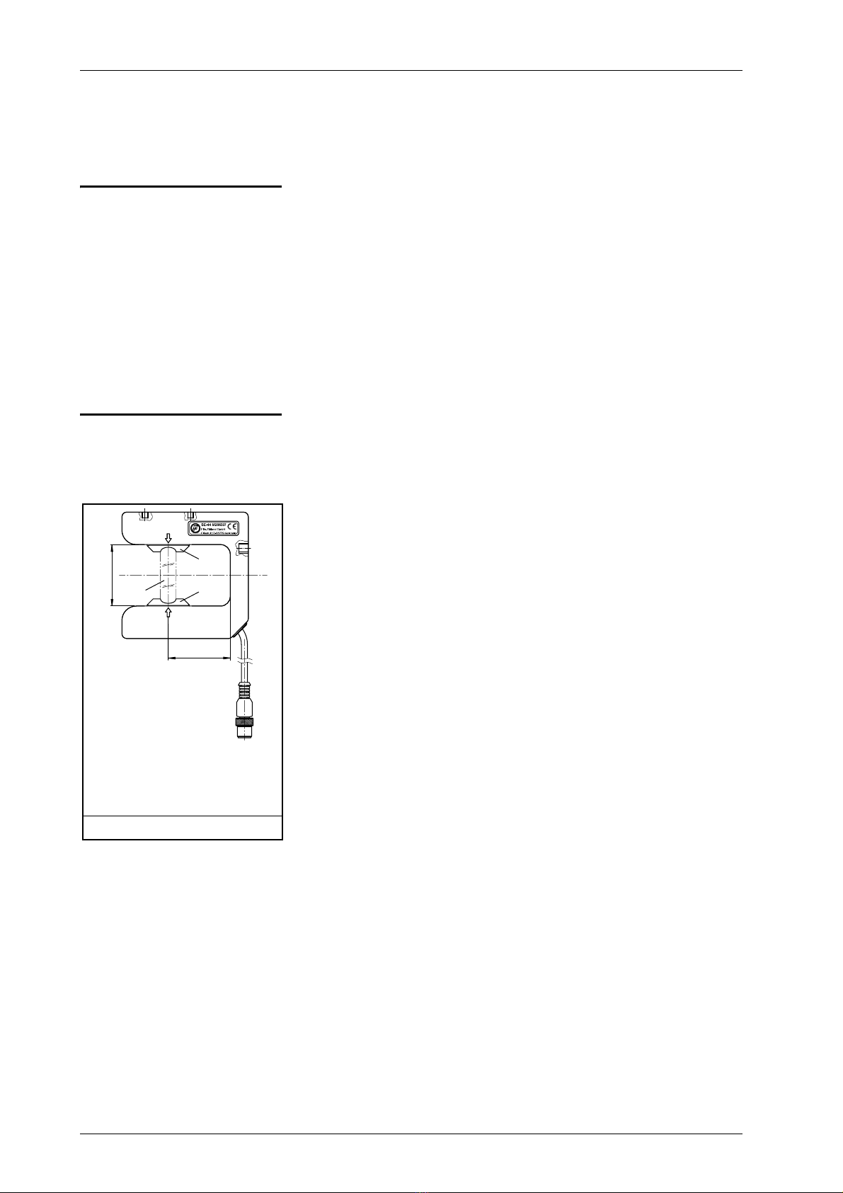
Dimensions . . . . . . . . . . . . . . . . . . . . . . . . . . . . . . . . . . . . . . . . . . . . . . . . . . . . . . 3-2
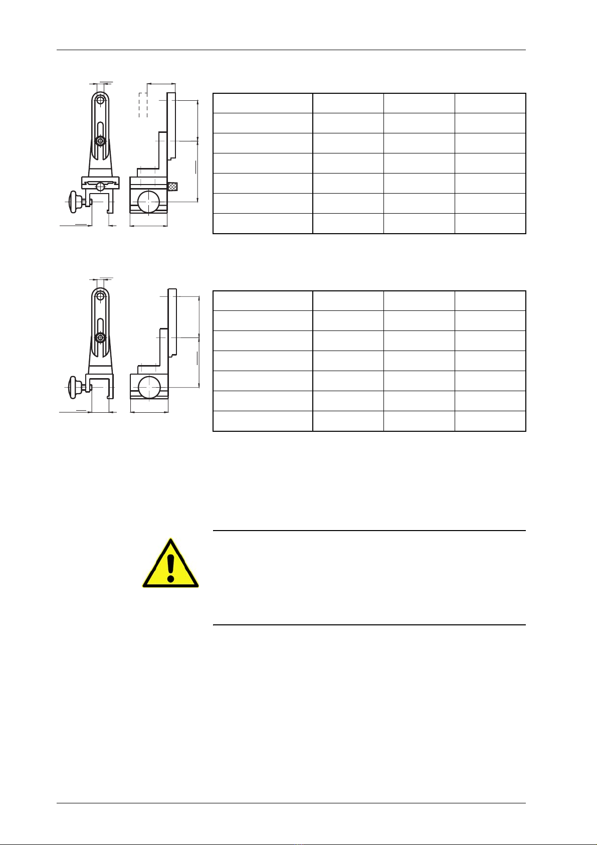
Mechanical fastening . . . . . . . . . . . . . . . . . . . . . . . . . . . . . . . . . . . . . . . . . . . . . . . 3-2
Sensor alignment . . . . . . . . . . . . . . . . . . . . . . . . . . . . . . . . . . . . . . . . . . . . . . . . . . 3-4
Electrical connection . . . . . . . . . . . . . . . . . . . . . . . . . . . . . . . . . . . . . . . . . . . . . . . . . . . 3-5
OPERATION 4-1
Settings . . . . . . . . . . . . . . . . . . . . . . . . . . . . . . . . . . . . . . . . . . . . . . . . . . . . . . . . . . . . . 4-1
MAINTENANCE 5-1
Maintenance . . . . . . . . . . . . . . . . . . . . . . . . . . . . . . . . . . . . . . . . . . . . . . . . . . . . . . . . . 5-1
Decommissioning . . . . . . . . . . . . . . . . . . . . . . . . . . . . . . . . . . . . . . . . . . . . . . . . . . . . . 5-1
TECHNICAL DATA 6-1
General information . . . . . . . . . . . . . . . . . . . . . . . . . . . . . . . . . . . . . . . . . . . . . . . . . . . 6-1
Properties . . . . . . . . . . . . . . . . . . . . . . . . . . . . . . . . . . . . . . . . . . . . . . . . . . . . . . . . . . . 6-1
Electrical connection . . . . . . . . . . . . . . . . . . . . . . . . . . . . . . . . . . . . . . . . . . . . . . . . . . . 6-2
Pin assignment . . . . . . . . . . . . . . . . . . . . . . . . . . . . . . . . . . . . . . . . . . . . . . . . . . . . 6-2
Standards . . . . . . . . . . . . . . . . . . . . . . . . . . . . . . . . . . . . . . . . . . . . . . . . . . . . . . . . . . . 6-2
SERVICE 7-1
Requests for Service . . . . . . . . . . . . . . . . . . . . . . . . . . . . . . . . . . . . . . . . . . . . . . . . . . . 7-1
Addresses . . . . . . . . . . . . . . . . . . . . . . . . . . . . . . . . . . . . . . . . . . . . . . . . . . . . . . . . . . . 7-1

INTRODUCTION 1 - 1
SE-44R / SE-44
Ultrasonic Sensor
www.maxcess.eu MI 1026 1 A
Einführung.fm
1 INTRODUCTION
About these operating
instructions These Operating Instructions describe the installation, operation
and maintenance of the SE-44 sensor and provide important
instructions for proper use.
These Operating Instructions are directed to both the system
construction master as well as the operator who uses the SE-44
sensor in production. The Operating Instructions must be read
and used by all persons who have the responsibility of installing,
operating and maintaining the SE-44 sensor.
The Operating Instructions must be carefully kept and must
always be available throughout the service life of the SE-44
sensor.
Note:
This operating manual also applies to sensor SE-44R.
Translation of the original Operating Instructions:
These Operating Instructions are a translation. The original
Operating Instructions were composed in German.
Proper usage The SE-44 sensor is used for no-contact measurements of the
lateral offset of the material web that is being controlled.
The SE-44 is suitable for:
– Web edge guiding and
– Web center guiding for dual application.
The SE-44
sensor can be used to control both opaque and
transparent materials
. A web guide controller must be used with
acoustically transparent materials to calibrate the sensor to the
material. For more information, see the web guide controller
operating instructions.
The
SE-44
sensor must only be used in accordance with its
intended purpose and in a technically flawless conditions.
The SE-44
sensor
must not be changed or opened

INTRODUCTION1 - 2
SE-44R / SE-44
Ultrasonic Sensor
www.maxcess.euMI 1026 1 A
The housing of the SE-44 sensor is made of coated synthetic
material (see page
6-1
). Please note the chemical resistance of
the synthetic material in use.
Improper usage – Operation outside of the technical specifications is not
permitted.
– Operation in areas where there is a danger of explosions is
prohibited.
– Any use other than the designated use is not permitted.
– The SE-44 sensor may not be used as a support, handle or
step.
Operating principle The SE-44 sensor works ultrasonically. This ensures the sensor
is ideally suited for optically transparent material webs. The
SE-44 is totally insensitive to ambient light.
The gap width GW and throat length GL are the characteristic
dimensions of the sensor.
The transmitter generates an ultrasonic field. Depending on how
far away the material web is in the ultrasonic field, a portion of
these ultrasonic waves strikes the receiver. Based on this, the
receiver generates the output signal from which the precise
position of the web edge is determined.
1–Receiver
2 – Sensor field of view
3–Source
GW- Gap width
GL - Throat length
Figure 1.1: Sensor SE-44
1
3
2
GW
GL

SAFETY INSTRUCTIONS 2 - 1
SE-44R / SE-44
Ultrasonic Sensor
www.maxcess.eu MI 1026 1 A
Sicherheit.fm
2 SAFETY INSTRUCTIONS
Important information To ensure safe and problem-free operation of the SE-44 sensor
it must be
– properly shipped and stored,
– properly mounted and placed in operation,
– properly used and carefully maintained.
Proper operation and careful maintenance will ensure a long
service life for the sensor.
Only persons who are acquainted with the installation,
commissioning, operation and maintenance of the sensor and
who possess the necessary qualifications for their activities may
work on the SE-44 sensor.
Please note the following:
– The content of these operating instructions
– The safety instructions printed on the unit
– The requirements of the machine manufacturer
– National, state and local requirements for accident
prevention and environmental protection
Information about
safety instructions The safety instructions and symbols described in this section
are used in these Operating instructions. They are used to avoid
possible dangers for users and to prevent material damage.
SIGNAL WORD
Source of danger and its results.
ÖAvoiding dangers
The signal word WARNING refers to the danger of moderate to
sever bodily injuries.
The signal word CAUTION refers to the danger of slight to
moderate bodily injuries or material damage.

SAFETY INSTRUCTIONS2 - 2
SE-44R / SE-44
Ultrasonic Sensor
www.maxcess.euMI 1026 1 A
Symbols
Warning/caution - dangerous area
Reference to general hazards that may result in bodily injuries
or damage to the device
Warning/caution - danger due to crushing
Refers to danger of injury caused by crushing
Warning/caution - danger due to cutting
Refers to danger of injury caused by cutting
Additional symbols
– This endash is followed by an enumeration.
∙This dot is followed by a prompt to do something.
Note:
Reference to important information.
Preventing hazards ∙The SE-44 sensor may not be used as a support, handle or
step. There is a danger that the sensor will become damaged
(breaking off/snapping), resulting in personal injury.
Mounting and
commissioning ∙A damaged sensor must not be installed or placed in
operation.
∙Assembly work must be performed while the machine is
stopped and protected against being turned on again.
∙All assembly tasks must only be performed when there is no
electrical power in the system.
∙The sensor must not be placed in operation unless it has
been securely mounted.
∙
Electrical connections should always be made or disconnected
on the sensor while there is no electrical power in the system.
Failure to observe these instruction may result in damage to
the sensor.

SAFETY INSTRUCTIONS 2 - 3
SE-44R / SE-44
Ultrasonic Sensor
www.maxcess.eu MI 1026 1 A
Sicherheit.fm
∙The parameters specified in Section
Technical data
must be
observed.
∙Only accessory and replacement parts that have been
approved by Fife-Tidland GmbH may be used.
∙No changes must be made to the sensor.
∙Electrical lines must not be subjected to any mechanical
loads.
Operation
∙Danger of injury by crushing
ÖDo not place your hands on or near moving parts (rollers,
material web, etc.) during operation.
∙Danger of injury due to cutting on the edge of the material
web
ÖDo not place your hands on the edge of the (moving)
material web during operation.
Maintenance
∙Danger of injury by crushing
ÖMaintenance work must only be performed on the sensor
when the power is turned off and the machine is stopped and
protected against being turned on again.

INSTALLATION3 - 1
SE-44R / SE-44
Ultrasonic Sensor
www.maxcess.euMI 1026 1 A
3 INSTALLATION
Transport and storage – The sensor and/or the unit on which the sensor is mounted
must be secured against slipping during transport.
– The sensor must be stored in a cool, dry place.
– The sensor must not be stored in the vicinity of powerful
magnetic fields. The electronic components of the sensor
may be damaged.
Mounting
WARNING
ÖAll assembly tasks on the sensor must be performed when
there is no electrical power in the system.
ÖAssembly tasks and mechanical settings must only be
performed when the machine has been stopped and has been
secured from being turned on again.
Mounting location –ProtectionClass:IP40
– Operating temperature: 0°C ... 60°C
– Relative humidity: up to 85% non-condensing
– Operating altitude: max. 5000m
– Not in places where there is a risk of explosions.

INSTALLATION 3 - 2
SE-44R / SE-44
Ultrasonic Sensor
www.maxcess.eu MI 1026 1 A
Installation.fm
Dimensions The
figure 3.1
shows the dimensions of the SE-44 sensor.
Mechanical fastening Drill holes are available on the housing for fastening the SE-44
sensor in place (
figure 3.1
). A large variety of assembly options
are possible in connection with the various sensor mountings.
Sensor mounts of types M and MO are available for various
square bars for assembling the SE-44 sensor with M8 or 7/16
drill holes
1-
Connection cable (Cable length for SE-44R: 80mm)
M8 –
M8 threading for assembly suspension type M or MO
M5 – M5 threading for assembly suspension type MB
Figure 3.1: Dimensions of SE-44

INSTALLATION3 - 3
SE-44R / SE-44
Ultrasonic Sensor
www.maxcess.euMI 1026 1 A
Sensor with assembly suspension type M
Sensor with assembly suspension type MO
Sensor with assembly suspension type MB
Sensor mounts of type MB are available for assembling the
SE-44 sensor on the M5 drill holes.
CAUTION:
Using long bolts introduces the risk of a short-circuit and
destroying the electronics that are located inside the housing.
ÖPlease note when assembling sensor SE-44 that only the
original M5*8 bolts or similar ones should be used.
Type A VK D
M-20/8 86 20 8
M-20/7/16 86 20 12
M-25/8 88 25 8
M-25/7/16 88 25 12
M-32/8 94 32 8
M-32/7/16 94 32 12
Type A VK D
MO-20/8 69 20 8
MO-20/7/16 69 20 12
MO-25/8 71 25 8
MO-25/7/16 71 25 12
MO-32/8 77 32 8
MO-32/7/16 77 32 12
VK=
D=
0-20
max 55
A=
62±20
VK=
D=
max 55
A= 62±20

INSTALLATION 3 - 4
SE-44R / SE-44
Ultrasonic Sensor
www.maxcess.eu MI 1026 1 A
Installation.fm
Sensor alignment The SE-44 sensor will work satisfactorily in a position
perpendicular to the web. If the application demands greater
precision, however, the sensor should be installed at an angle of
45° ≤ϕ≤55° to the web. For optimal performance of the
sensor, the angle must be 45° (see
figure 3.3)
.
Sensor-
mount
square bar
ABC
Xmax.
length
MB-20 20 1600 68 42,5 15,5
MB-25 25 2200 71 46,5 18,5
MB-32 32 2400 76 51,5 23,5
1–squarebar
Figure 3.2: SE-44 with assembly suspension type MB
1
1–Web 2-Sensoraxis
Figure 3.3: Sensor alignment
ϕ=45°
1
2

INSTALLATION3 - 5
SE-44R / SE-44
Ultrasonic Sensor
www.maxcess.euMI 1026 1 A
Electrical connection
CAUTION:
The sensor could be damaged.
Ö
Electrical connections should always be made or disconnected
on the sensor while there is no electrical power in the system
ÖWhen attaching the connector with the jack on the sensor,
pay close attention to the guide and groove! The connector and
jack must not be connected with incorrect orientation or by
force, as this will destroy the sensor.
The sensor must be connected to the web guide controller
according to the system diagram in the system documentation.

OPERATION 4 - 1
SE-44R / SE-44
Ultrasonic Sensor
www.maxcess.eu MI 1026 1 A
Betrieb.fm
4 OPERATION
WARNING:
Danger of injury by crushing
ÖDo not place your hands on or near moving parts (rollers,
material web, etc.) during operation.
WARNING:
Danger of injury due to cutting on the edge of the material web
ÖDo not place your hands on the edge of the (moving) material
web during operation.
CAUTION:
Depending on the material of the web that is being guided, it is
possible that the web edge could grind against the inside of the
sensor fork, resulting in notches and incisions on the sensor.
The sensor could become unusable.
Settings All settings required for operating the SE-44 sensor are
performed with the web guide controller. Information on this
topic is available in the Operating Instructions for the web guide
controller.
Before the SE-44 is used for working with acoustically
transparent material, the sensor must always be calibrated to
the contrast with the web guide controller.

MAINTENANCE5 - 1
SE-44R / SE-44
Ultrasonic Sensor
www.maxcess.euMI 1026 1 A
5 MAINTENANCE
WARNING:
Danger of injury by crushing.
ÖMaintenance work must only be performed on the sensor
when the power is turned off and the machine is stopped and
protected against being turned on again.
Maintenance The foam coverings of the ultrasonic converters must be
cleaned regularly, depending on how dirty the environment is,
of dust and other impurities. To do this, carefully brush off the
foam coverings or blow them off with compressed air. Make
certain when you do this that no particles get into the inside of
the housing.
No additional maintenance tasks are required for the SE-44
sensor.
Decommissioning ∙Turn off the electrical power to the system.
∙Disconnect the signal cable from the sensor.
∙Unscrew the sensor from its bracket.
∙Store the sensor in a cool, clean and dry place.
OR
Dispose of the sensor according to your national
requirements.

TECHNICAL DATA 6 - 1
SE-44R / SE-44
Ultrasonic Sensor
www.maxcess.eu MI 1026 1 A
TechnDaten.fm
6 TECHNICAL DATA
General information Dimensions
Gap widths: 51mm
effective gap width at 45° mounting: 19mm
effective gap width at 55° mounting: 28mm
Throat length: 51mm
Weight: 130g
Protection class
IP40
Ambient conditions
Ambient temperature: 0°C - 60°C
Relative humidity: up to 85% non-condensing
Operating altitude max. 5000m above sea level
Materials used
Housing: ABS (acrylonitrile/butadiene/styrene), nickel-plated.
Data sheet can be requested on these material (ABS: EK0143).
Properties Source
Ultrasonic
Frequency
ca. 40kHz
Proportional band
10mm (Sensor field of view)
Linearity
10% max. error (10% .. 90%)
Web plane change
5% max. error (at 45° angle between web and sensor)
Temperature error
7% (at 10°C .. 50°C)

TECHNICAL DATA6 - 2
SE-44R / SE-44
Ultrasonic Sensor
www.maxcess.euMI 1026 1 A
Electrical connection Power supply
10V ... 15V at 40mA
Output signal
0 - 10mA
Pin assignment
Standards The SE-44 sensor was constructed in accordance with the
standards and regulations of the European Union. A Declaration
of Conformity is available.
1 – Power supply
2 - Not assigned
3 - P-GND
4 - Output signal
X - key
Housing = shield
Figure 6.1: M12 connector, SE-44
2
1
3
4
X
4
1
3
2
X
1–Outputsignal
2 - Power supply
3 - P-GND
4 - Not assigned
X - notch
Housing = shield
Figure 6.2: M9 female connector, SE-44R
X
3
2
4
1
4
1
3
2
X

SE-44R / SE-44
Ultrasonic Sensor
www.maxcess.eu MI 1026 1 A
Service.fm
SERVICE 7 - 1
7 SERVICE
Requests for Service When requesting service, please have a copy of the order
confirmation ready with the order number.
When ordering replacement parts, please indicate, (where
possible) Part Number, Drawing Number and Model description.
Please be careful to keep all documents accompanying the
product in a safe place. This will allow us to help you more
quickly in the event that service is required.
Addresses To request service, or if you need replacement parts, please
contact one of the following addresses.
Fife-Tidland GmbH
Max-Planck-Straße 8 Siemensstraße 13-15
65779 Kelkheim 48683 Ahaus
Germany Germany
Phone: +49 - 6195 - 7002 - 0
Fax: +49 - 6195 - 3018
E-Mail: [email protected]
Web: www.maxcess.eu
Fife Corporation
Post Office Box 26508
Oklahoma City, OK 73126, USA
Phone: +1 - 405 - 755 - 1600
Fax: +1 - 405 - 755 - 8425
E-Mail: [email protected]
Web: www.maxcessintl.com

SERVICE7 - 2
© 2016 Maxcess
EUROPE, MIDDLE EAST
AND AFRICA
Tel +49.6195.7002.0
Fax +49.6195.3018
www.maxcess.eu
NORTH, CENTRAL
AND SOUTH AMERICA
Tel +1.405.755.1600
Fax +1.405.755.8425
www.maxcessintl.com
CHINA
Tel +86.756.881.9398
Fax +86.756.881.9393
JAPAN
Tel +81.43.421.1622
Fax +81.43.421.2895
www.maxcess.jp
INDIA
Tel +91.22.27602633
Fax +91.22.27602634
www.maxcess.in
This manual suits for next models
2
Table of contents
Other Maxcess Accessories manuals

Maxcess
Maxcess SE-26B User manual

Maxcess
Maxcess FIFE DSE-22 User manual

Maxcess
Maxcess SE-22 User manual

Maxcess
Maxcess FIFE DSE-41 User manual

Maxcess
Maxcess FIFE DSE-31 User manual

Maxcess
Maxcess FIFE DSE-11 User manual

Maxcess
Maxcess FIFE DSE-23 User manual

Maxcess
Maxcess FIFE DSE-15 User manual

Maxcess
Maxcess FIFE DST-1 User manual

Maxcess
Maxcess FIFE DSE-15 User manual