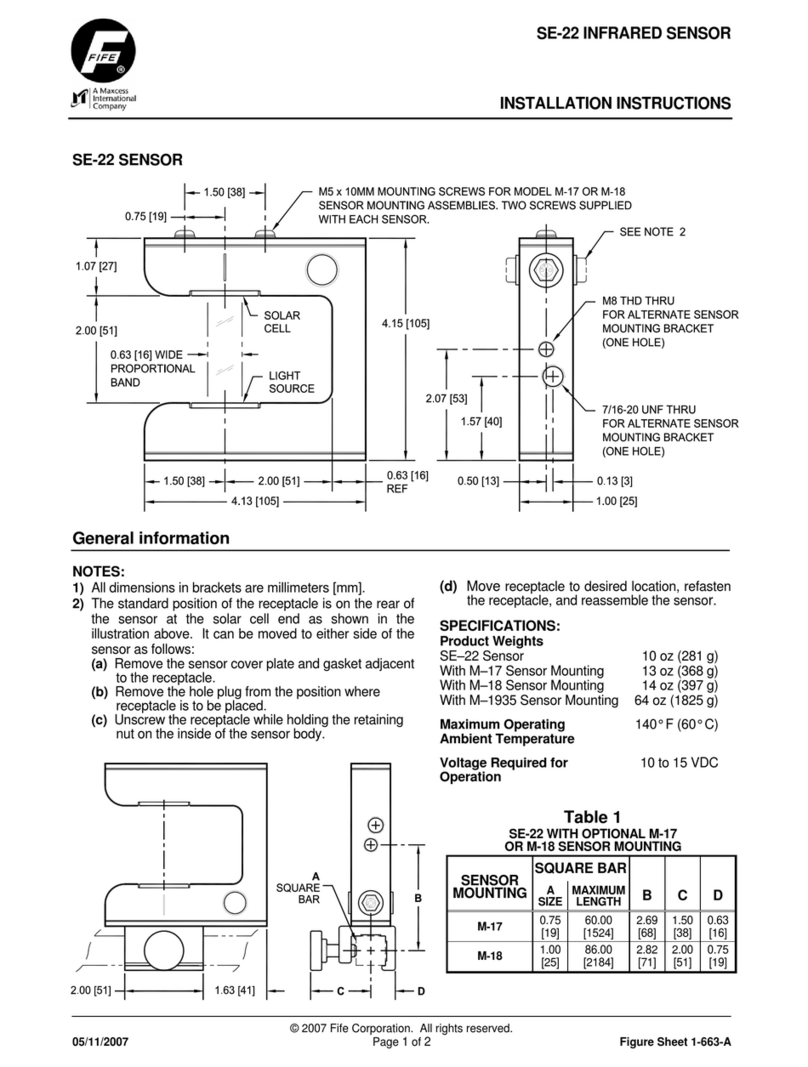
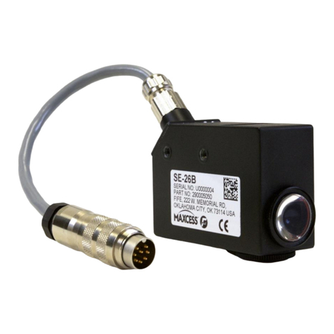
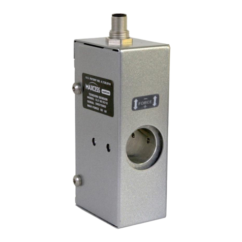
Maxcess Fife-Tidland SE-46 User manual

MI 1 1039 B
SE-46.Deckblatt.fm
Fife-Tidland GmbH
GLOBAL WEB MANAGEMENT SOLUTION
guiding inspection slitting winding
Fifestraße 1 - 65779 Kelkheim - Deutschland
Siemensstraße 13-15 - 48683 Ahaus - Deutschland
Telefon: +49 - 6195 - 7002 - 0 Fax: +49 - 6195 - 7002 - 933
GB
Digital Line Sensor
SE-46
Operating Instructions

CONTENTS
SE-46 26.01.09MI 1 1039 B
I
INTRODUCTION 1-1
About these operating instructions . . . . . . . . . . . . . . . . . . . . . . . . . . . . . . . . . . . . . . . 1-1
Proper use . . . . . . . . . . . . . . . . . . . . . . . . . . . . . . . . . . . . . . . . . . . . . . . . . . . . . . . . . . 1-1
Operating principle . . . . . . . . . . . . . . . . . . . . . . . . . . . . . . . . . . . . . . . . . . . . . . 1-2
Options . . . . . . . . . . . . . . . . . . . . . . . . . . . . . . . . . . . . . . . . . . . . . . . . . . . . . . . 1-3
SAFETY INSTRUCTIONS 2-1
Notes on using the SE-46 sensor . . . . . . . . . . . . . . . . . . . . . . . . . . . . . . . . . . . . . . . . . 2-1
Information about safety instructions . . . . . . . . . . . . . . . . . . . . . . . . . . . . . . . . . . . . . 2-1
Safety instructions . . . . . . . . . . . . . . . . . . . . . . . . . . . . . . . . . . . . . . . . . . . . . . . 2-1
Symbols . . . . . . . . . . . . . . . . . . . . . . . . . . . . . . . . . . . . . . . . . . . . . . . . . . . . . . 2-2
Hazards . . . . . . . . . . . . . . . . . . . . . . . . . . . . . . . . . . . . . . . . . . . . . . . . . . . . . . . . . . . . 2-2
Installation and commissioning . . . . . . . . . . . . . . . . . . . . . . . . . . . . . . . . . . . . . 2-2
Operation . . . . . . . . . . . . . . . . . . . . . . . . . . . . . . . . . . . . . . . . . . . . . . . . . . . . . 2-3
Maintenance . . . . . . . . . . . . . . . . . . . . . . . . . . . . . . . . . . . . . . . . . . . . . . . . . . . 2-3
INSTALLATION 3-1
Transport and storage . . . . . . . . . . . . . . . . . . . . . . . . . . . . . . . . . . . . . . . . . . . . . . . . . 3-1
Scope of delivery . . . . . . . . . . . . . . . . . . . . . . . . . . . . . . . . . . . . . . . . . . . . . . . . . . . . . 3-1
Mounting . . . . . . . . . . . . . . . . . . . . . . . . . . . . . . . . . . . . . . . . . . . . . . . . . . . . . . . . . . 3-1
Dimensions . . . . . . . . . . . . . . . . . . . . . . . . . . . . . . . . . . . . . . . . . . . . . . . . . . . . 3-2
Installation location of sensor SE-46 . . . . . . . . . . . . . . . . . . . . . . . . . . . . . . . . . . 3-2
Mechanical fastening . . . . . . . . . . . . . . . . . . . . . . . . . . . . . . . . . . . . . . . . . . . . 3-4
Electrical connection . . . . . . . . . . . . . . . . . . . . . . . . . . . . . . . . . . . . . . . . . . . . . . . . . . 3-6
Connections on sensor SE-46 . . . . . . . . . . . . . . . . . . . . . . . . . . . . . . . . . . . . . . 3-6
COMMISSIONING OF THE SE-46 SENSOR 4-1
Sensor SE-46 . . . . . . . . . . . . . . . . . . . . . . . . . . . . . . . . . . . . . . . . . . . . . . . . . . . . . . . . 4-1
COMMISSIONING OF WEB GUIDE CONTROLLERS 5-1
D-MAX . . . . . . . . . . . . . . . . . . . . . . . . . . . . . . . . . . . . . . . . . . . . . . . . . . . . . . . . . . . . 5-1
1. Calibrating the analog signal inputs of the D-MAX Controller . . . . . . . . . . . . 5-1
2. Setting the ASC (Automatic Sensor Control) . . . . . . . . . . . . . . . . . . . . . . . . . 5-6
3. Setting the polarity and gain . . . . . . . . . . . . . . . . . . . . . . . . . . . . . . . . . . . . . 5-6
Operation . . . . . . . . . . . . . . . . . . . . . . . . . . . . . . . . . . . . . . . . . . . . . . . . . . . . . 5-7
DP-20 . . . . . . . . . . . . . . . . . . . . . . . . . . . . . . . . . . . . . . . . . . . . . . . . . . . . . . . . . . . . . 5-8
1. Calibrating the analog signal inputs of the DP-20 . . . . . . . . . . . . . . . . . . . . . 5-8
2. Setting the ASC (Automatic Sensor Control) . . . . . . . . . . . . . . . . . . . . . . . . 5-12
3. Setting the polarity and gain . . . . . . . . . . . . . . . . . . . . . . . . . . . . . . . . . . . . 5-12
Operation . . . . . . . . . . . . . . . . . . . . . . . . . . . . . . . . . . . . . . . . . . . . . . . . . . . . 5-13
CDP-01 . . . . . . . . . . . . . . . . . . . . . . . . . . . . . . . . . . . . . . . . . . . . . . . . . . . . . . . . . . . 5-14
1. Calibrating Analog signal inputs . . . . . . . . . . . . . . . . . . . . . . . . . . . . . . . . . 5-14
2. Setting the ASC (Automatic Sensor Control) . . . . . . . . . . . . . . . . . . . . . . . . 5-17
3. Setting the polarity and gain . . . . . . . . . . . . . . . . . . . . . . . . . . . . . . . . . . . . 5-18
Operation . . . . . . . . . . . . . . . . . . . . . . . . . . . . . . . . . . . . . . . . . . . . . . . . . . . . 5-19
OPERATION VIA SENSOR KEYBOARD 6-1
Precondition . . . . . . . . . . . . . . . . . . . . . . . . . . . . . . . . . . . . . . . . . . . . . . . . . . . . . . . . 6-1
Safety instructions . . . . . . . . . . . . . . . . . . . . . . . . . . . . . . . . . . . . . . . . . . . . . . . . . . . . 6-1

CONTENTS
SE-4626.01.09 MI 1 1039 B
MI10391BIVZ.fm
II
User interface . . . . . . . . . . . . . . . . . . . . . . . . . . . . . . . . . . . . . . . . . . . . . . . . . . . . . . . 6-2
Keys and their functions . . . . . . . . . . . . . . . . . . . . . . . . . . . . . . . . . . . . . . . . . . 6-2
Displays . . . . . . . . . . . . . . . . . . . . . . . . . . . . . . . . . . . . . . . . . . . . . . . . . . . . . . . 6-2
SE-46 operation states . . . . . . . . . . . . . . . . . . . . . . . . . . . . . . . . . . . . . . . . . . . . . . . . . 6-4
Instructions for calibration . . . . . . . . . . . . . . . . . . . . . . . . . . . . . . . . . . . . . . . . . . . . . . 6-4
Select a suitable reference . . . . . . . . . . . . . . . . . . . . . . . . . . . . . . . . . . . . . . . . . 6-4
Scan frequency . . . . . . . . . . . . . . . . . . . . . . . . . . . . . . . . . . . . . . . . . . . . . . . . . 6-5
Sensor mode . . . . . . . . . . . . . . . . . . . . . . . . . . . . . . . . . . . . . . . . . . . . . . . . . . . 6-6
Calibration of the SE-46 . . . . . . . . . . . . . . . . . . . . . . . . . . . . . . . . . . . . . . . . . . . . . . . 6-7
Enhanced functionality . . . . . . . . . . . . . . . . . . . . . . . . . . . . . . . . . . . . . . . . . . . . . . . . 6-8
Deviation Tolerance . . . . . . . . . . . . . . . . . . . . . . . . . . . . . . . . . . . . . . . . . . . . . . 6-8
Active Profile . . . . . . . . . . . . . . . . . . . . . . . . . . . . . . . . . . . . . . . . . . . . . . . . . . . 6-8
Interrupted reference . . . . . . . . . . . . . . . . . . . . . . . . . . . . . . . . . . . . . . . . . . . . 6-9
Active field of view . . . . . . . . . . . . . . . . . . . . . . . . . . . . . . . . . . . . . . . . . . . . . . 6-9
PARAMETER SETTING VIA SENSOR KEYBOARD 7-1
Notes . . . . . . . . . . . . . . . . . . . . . . . . . . . . . . . . . . . . . . . . . . . . . . . . . . . . . . . . . . . . .7-1
Menu structure . . . . . . . . . . . . . . . . . . . . . . . . . . . . . . . . . . . . . . . . . . . . . . . . . . . . . . 7-1
M1 Deviation Tolerance . . . . . . . . . . . . . . . . . . . . . . . . . . . . . . . . . . . . . . . . . . . . . . . 7-2
M2 Scan Frequency . . . . . . . . . . . . . . . . . . . . . . . . . . . . . . . . . . . . . . . . . . . . . . . . . . . 7-3
M3 Type of Illumination . . . . . . . . . . . . . . . . . . . . . . . . . . . . . . . . . . . . . . . . . . . . . . . 7-5
M4 Active Profile . . . . . . . . . . . . . . . . . . . . . . . . . . . . . . . . . . . . . . . . . . . . . . . . . . . . . 7-6
M5 Hardware Settings . . . . . . . . . . . . . . . . . . . . . . . . . . . . . . . . . . . . . . . . . . . . . . . . . 7-8
M5.1 Distance Gauge . . . . . . . . . . . . . . . . . . . . . . . . . . . . . . . . . . . . . . . . . . . . . . . . . 7-9
M5.3 Simulate Analog Signals . . . . . . . . . . . . . . . . . . . . . . . . . . . . . . . . . . . . . . . . . . 7-10
MX menus . . . . . . . . . . . . . . . . . . . . . . . . . . . . . . . . . . . . . . . . . . . . . . . . . . . . . . . . 7-12
MX.1 - Active Field of View . . . . . . . . . . . . . . . . . . . . . . . . . . . . . . . . . . . . . . . . . . . . 7-13
MX.2 - Profile Switching activated ? . . . . . . . . . . . . . . . . . . . . . . . . . . . . . . . . . . . . . 7-15
THE D-MAX OPERATOR INTERFACE IS USED FOR CONTROL 8-1
Notes . . . . . . . . . . . . . . . . . . . . . . . . . . . . . . . . . . . . . . . . . . . . . . . . . . . . . . . . . . . . .8-1
Priority of keyboard and displays . . . . . . . . . . . . . . . . . . . . . . . . . . . . . . . . . . . . 8-1
Top level . . . . . . . . . . . . . . . . . . . . . . . . . . . . . . . . . . . . . . . . . . . . . . . . . . . . . . . . . . . 8-2
Calibration of the SE-46 . . . . . . . . . . . . . . . . . . . . . . . . . . . . . . . . . . . . . . . . . . . . . . . 8-2
D-MAX menu of the SE-46 . . . . . . . . . . . . . . . . . . . . . . . . . . . . . . . . . . . . . . . . . . . . . 8-3
Menu structure . . . . . . . . . . . . . . . . . . . . . . . . . . . . . . . . . . . . . . . . . . . . . . . . . 8-3
Menu identification . . . . . . . . . . . . . . . . . . . . . . . . . . . . . . . . . . . . . . . . . . . . . . 8-3
APPLICATION EXAMPLES 9-1
Edges of printed images . . . . . . . . . . . . . . . . . . . . . . . . . . . . . . . . . . . . . . . . . . . . . . . 9-1
Guiding lines . . . . . . . . . . . . . . . . . . . . . . . . . . . . . . . . . . . . . . . . . . . . . . . . . . . . . . . . 9-2
Complex patterns as guiding lines . . . . . . . . . . . . . . . . . . . . . . . . . . . . . . . . . . . . . . . . 9-3
Setting the width of the reference pattern . . . . . . . . . . . . . . . . . . . . . . . . . . . . . 9-5
Print marks . . . . . . . . . . . . . . . . . . . . . . . . . . . . . . . . . . . . . . . . . . . . . . . . . . . . . . . . . 9-5
MAINTENANCE 10-1
Maintenance work . . . . . . . . . . . . . . . . . . . . . . . . . . . . . . . . . . . . . . . . . . . . . . . . . . 10-1
Decommissioning . . . . . . . . . . . . . . . . . . . . . . . . . . . . . . . . . . . . . . . . . . . . . . . . . . . 10-1

CONTENTS
SE-46 26.01.09MI 1 1039 B
III
TROUBLESHOOTING 11-1
Information . . . . . . . . . . . . . . . . . . . . . . . . . . . . . . . . . . . . . . . . . . . . . . . . . . . . . . . . 11-1
Display possibilities . . . . . . . . . . . . . . . . . . . . . . . . . . . . . . . . . . . . . . . . . . . . . 11-1
Procedure . . . . . . . . . . . . . . . . . . . . . . . . . . . . . . . . . . . . . . . . . . . . . . . . . . . . 11-1
LED display on the SE-46 . . . . . . . . . . . . . . . . . . . . . . . . . . . . . . . . . . . . . . . . . . . . . . 11-2
Faults . . . . . . . . . . . . . . . . . . . . . . . . . . . . . . . . . . . . . . . . . . . . . . . . . . . . . . . . . . . . 11-4
Problems when calibrating the reference . . . . . . . . . . . . . . . . . . . . . . . . . . . . . . . . . . 11-5
Error message when exiting a menu . . . . . . . . . . . . . . . . . . . . . . . . . . . . . . . . 11-5
Rollback . . . . . . . . . . . . . . . . . . . . . . . . . . . . . . . . . . . . . . . . . . . . . . . . . . . . . 11-5
Problems with guiding . . . . . . . . . . . . . . . . . . . . . . . . . . . . . . . . . . . . . . . . . . . . . . . 11-6
Error messages on the optional D-MAX operator interface . . . . . . . . . . . . . . . . . . . . 11-7
Error message when exiting a menu . . . . . . . . . . . . . . . . . . . . . . . . . . . . . . . . 11-7
Error messages when cancelling a calibration . . . . . . . . . . . . . . . . . . . . . . . . . 11-7
TECHNICAL DATA 12-1
General information . . . . . . . . . . . . . . . . . . . . . . . . . . . . . . . . . . . . . . . . . . . . . . . . . 12-1
Optical properties . . . . . . . . . . . . . . . . . . . . . . . . . . . . . . . . . . . . . . . . . . . . . . . . . . . 12-1
Electrical connection . . . . . . . . . . . . . . . . . . . . . . . . . . . . . . . . . . . . . . . . . . . . . . . . . 12-2
X1 plug connector . . . . . . . . . . . . . . . . . . . . . . . . . . . . . . . . . . . . . . . . . . . . . 12-2
X2 plug connector . . . . . . . . . . . . . . . . . . . . . . . . . . . . . . . . . . . . . . . . . . . . . 12-2
Output signals . . . . . . . . . . . . . . . . . . . . . . . . . . . . . . . . . . . . . . . . . . . . . . . . . 12-2
Power supply . . . . . . . . . . . . . . . . . . . . . . . . . . . . . . . . . . . . . . . . . . . . . . . . . 12-3
Standards and regulations . . . . . . . . . . . . . . . . . . . . . . . . . . . . . . . . . . . . . . . . . . . . . 12-3
APPENDIX A - MENU STRUCTURE 13-1
APPENDIX B - SCAN FREQUENCY DIAGRAM 14-1
APPENDIX C - MENU STRUCTURE OF D-MAX 15-1
SERVICE 16-1
Requests for Service . . . . . . . . . . . . . . . . . . . . . . . . . . . . . . . . . . . . . . . . . . . . . . . . . 16-1
Addresses . . . . . . . . . . . . . . . . . . . . . . . . . . . . . . . . . . . . . . . . . . . . . . . . . . . . . . . . . 16-1

1 - 1
INTRODUCTION
SE-4626.01.09 MI 1 1039 B
SE-46.Einführung.fm
1 INTRODUCTION
About these operating
instructions These Operating Instructions describe the commissioning,
operation and maintenance of the SE-46 digital line sensor
and provide important instructions for proper use.
These operating instructions are intended for both the
system construction master as well as the operator who uses
the SE-46 sensor in production. The Operating Instructions
must be read and applied by everyone who is responsible for
commissioning, operating or maintaining the SE-46 sensor.
The Operating Instructions must be carefully kept and must
always be available throughout the service life of the SE-46
sensor.
Translation of the original Operating Manual:
This Operating Manual is a translation. The original
Operating Manual was composed in German.
Proper use
The SE-46 sensor is a line sensor for web guiding systems
with
an optical viewing range of 30mm. The SE-46 recognises a
calibrated reference on the material web and generates
guide signals from it that are used together with a web guide
controller from Fife-Tidland GmbH for precise guiding of the
material web.
Note:
The SE-46 sensor must not be opened.
If the SE-46 sensor is opened, no claims will be honoured
under the warranty.

SE-46 26.01.09MI 1 1039 B
1 - 2
INTRODUCTION
Operating principle Active illumination (7) makes the material web brighter,
which makes Information such as contrast transitions, lines or
structures more visible. The SE-46 sensor samples this
information with an imager (8) and compares it with an
image line of the template saved during the calibration
(reference). The sensor derives
the position difference (offset)
from this information if the similarity is sufficient.
A target light (9 - Fig. 1.1) makes it possible to display
detected positions on the material web while operation
continues. The distance between the target light and the
viewing area is 45mm (see also A in Fig. 1.2, page 1-3).
1Keyboard
2 Threading for sensor bracket
3Softwarenumbers
4 Connections
5 Ambient light hood
6Nameplate
7 Illumination
8Imager
9 Target light
Fig. 1.1: Layout of the SE-46 sensor
1
5
2
4
3
7
8
9
6

1 - 3
INTRODUCTION
SE-4626.01.09 MI 1 1039 B
SE-46.Einführung.fm
The notch in the front (2) of the ambient light hood
identifies the center of the sensor field of view.
When the distance between the sensor and material web (7)
is 10mm, the notch in the side (3) of the ambient light hoot
is located exactly above the viewing area.
The side slots (4) in the ambient light hood indicate the
viewing direction (6) independently of the distance from the
sensor to the material web.
Options Illumination
The SE-46 sensor provides high-intensity colour lighting
(RGB) for on-light applications that can be used to make
even very faint orientation features visible.
1 Ambient light hood
2 Marking of sensor center line
3 Marking of viewing area at a
distance of 10mm
4 Marking of viewing direction
5Targetlight
6 Viewing direction
7Materialweb
8 Sensor field of view
A Distance from the viewing area to the target
light
Fig. 1.2: Ambient light hood and target light
1
5
2
4
6
3
45mm
7
A
8

SE-46 26.01.09MI 1 1039 B
1 - 4
INTRODUCTION
Fife-Tidland GmbH offers additional types of illumination for
other applications that cannot be detected with this standard
lighting.
Beginning with firmware version 004, the sensor can also be
used for back light applications.
A D-MAX operator interface is used for control
The SE-46 sensor can also be set and calibrated with a
D-MAX operator device. This may be a convenient solution,
for example, if the SE-46 is mounted in a place that is not
suitable for operation or if guiding of the material web is
implemented by a D-MAX system.
Fig. 1.3: D-MAX operator interface

2 - 1
SAFETY INSTRUCTIONS
SE-4626.01.09 MI 1 1039 B
SE-46.Sicherheit.fm
2 SAFETY INSTRUCTIONS
Notes on using the SE-46
sensor Problem-free and reliable operation of the SE-46 sensor
requires that the system be properly transported, stored,
installed and placed in operation. Proper operation and
careful maintenance will ensure a long service life for your
sensor.
Only persons who are acquainted with the installation,
commissioning, operation and maintenance of the sensor
and who possess the necessary qualifications for their
activities may work on the SE-46 sensor.
Please note the following:
–The content of these Operating Instructions
–National and local requirements for accident prevention
and environmental protection
Information about safety
instructions The safety instructions and symbols described in this section
are used in these Operating Instructions. They are used to
avoid possible dangers for users and to prevent material
damage.
Safety instructions
SIGNAL WORD:
Source of danger and its results.
ÖAvoiding dangers.
The signal word WARNING refers to the danger of moderate
to severe bodily injuries.
The signal word CAUTION refers to the danger of slight to
moderate bodily injuries or material damage.

SE-46 26.01.09MI 1 1039 B
2 - 2
SAFETY INSTRUCTIONS
Symbols
Warning/caution - dangerous area
Reference to general hazards that may result in bodily injuries
or damage to the device
Warning/caution - danger due to crushing
Refers to danger of injury caused by crushing
Warning/caution - danger due to cutting
Refers to danger of injury caused by cutting
Warning/caution - danger due to temporary blinding
Refers to dangers that may be caused by being briefly
blinded.
Additional symbols
–This dash is followed by an enumeration.
zThis dot is followed by a prompt to do something.
1. Prompts following describing what to do in numbered
order.
Note:
Reference to important information.
Hazards Observance of the following points is mandatory to ensure
reliable work with the SE-46 sensor.
Installation and
commissioning zIf a sensor is damaged, it must not be installed or placed
in operation.
zAll assembly tasks on the sensor must only be performed
when there is no electrical power in the system.
zAssembly tasks and mechanical settings must only be
performed when the machine has been stopped and
secured from being turned on again.

2 - 3
SAFETY INSTRUCTIONS
SE-4626.01.09 MI 1 1039 B
SE-46.Sicherheit.fm
zThe sensor must only be placed in operation if it has been
securely mounted.
zElectrical connections on the sensor should always be
made or disconnected while there is no electrical power
in the system. Failure to observe this instruction may
result in damage to the sensor.
zThe parameters specified in Section Technical data must
be observed.
zOnly accessories and replacement parts that have been
approved by Fife Tidland may be used.
zNo changes may be made to the sensor.
zAvoid direct visual contact with the sensor lighting. The
radiated power is very high and may result in temporary
blindness or damage to eyes.
Temporary blindness or dazzling may diminish visual
capacity and cause afterimages. This in turn may result in
accidents in the workplace.
Care must therefore be taken not to place the sensor in
operation until it is mechanically fastened to its intended
support rod and the material web has been moved in
front of the sensor's field of vision.
Operation
zDuring operation, do not touch or reach close to moving
parts (rollers, web). There is a danger of being crushed.
zThere is a danger of being cut by the web edge due to
the web material and/or the movement of the web itself.
zAvoid direct visual contact with the sensor lighting during
operation (for example during a web change).
Maintenance zMaintenance work must only be performed on the sensor
when the power is turned off, the machine is stopped,
and it is protected against being turned back on.

SE-46 26.01.09MI 1 1039 B
3 - 1
INSTALLATION
3 INSTALLATION
Transport and storage –The sensor must be protected against slipping during
transport.
–The sensor must be stored in a cool, clean, and dry place.
–The sensor must not be stored close to strong magnetic
fields. The electronic components of the sensor could be
damaged.
Scope of delivery –Sensor SE-46
The model designation, serial number, and the firmware
and software numbers are on the nameplates on the
housing.
–Operating Instructions
Mounting
WARNING:
ÖAll assembly tasks on the sensor must be performed when
there is no electrical power in the system.
ÖAssembly tasks and mechanical settings must only be
performed when the machine has been stopped and secured
from being turned on again.

3 - 2
INSTALLATION
SE-4626.01.09 MI 1 1039 B
SE-46.Installation.fm
Dimensions Fig 3.1 shows the dimensions of sensor SE-46.
Installation location of sensor
SE-46
–Protection class: IP54
–Operating temperature: 0°C ... 60°C
Relative humidity up to 90% non-condensing
–Protected from vibrations
–Do not place close to strong magnetic fields:
The electronic components may be damaged.
–The SE-46 sensor is normally mounted at a distance of
10mm from the material web (see C in Fig 3.1).
–Unless another arrangement is recommended, mount the
SE-46 sensor directly behind the offset pivot guide. The
greater the distance from the sensor to the offset pivot
guide, the lower the guiding accuracy.
A Mounting holes
BMaterialweb
C Recommended distance from the material web to
the sensor
DViewingarea
E Sensor field of view
Fig. 3.1: Dimensions of sensor SE-46
B
C
A
D
E

SE-46 26.01.09MI 1 1039 B
3 - 3
INSTALLATION
–The material edge must be guided through a support
roller in the sensor field of view so that there is no plane
change (see Fig 3.2).
–The material web must run parallel to the lower edge of
the sensor (see Fig 3.3).
–On-light applications:
Ideally the viewing area on the material web should be on
or just behind the support roller (see Fig 3.3).
–Back light applications with external light source:
The SE-46 sensor must be mounted either between two
rollers or close behind one support roller.
0);58G
Fig. 3.2: Assembly location of SE-46
A
DAAE
D?
89
C
89
89
C
89
R
89
@9 0!(59
0);589F
@C
1 Material web 2 Support roller
Fig. 3.3: Sensor SE-46 and support roller
1
2

3 - 4
INSTALLATION
SE-4626.01.09 MI 1 1039 B
SE-46.Installation.fm
Mechanical fastening
To assist in mounting the SE-46 sensor, holes have been
drilled in the housing (see A in Fig 3.1). Together with
various sensor bracket, this provides a wide range of
installation options.
Assembly of the SE-46 with sensor bracket M
Sensor bracket with distance adjustment
zScrew the micro-adjusting device (1) onto the SE-46
sensor with the M4x6 screws
CAUTION
If longer screws are used, there is a danger of
destroying the electronics located in the
sensor's housing.
ÖBecause of this, make certain when fastening the sensor
bracket onto the SE-46 sensor that only the original M4x6
screws or identical ones are used.
zScrew the adapter plate (2) onto the micro-adjusting
device (1) with the M4x6 screws (5)
zScrew the sensor bracket (3) onto the adapter plate with
the M5x6 (4) screws
zScrew in the star knob (6)
zPush the assembled unit onto the rectangular bar
Note:
Sensor bracket M can also be assembled directly onto the
sensor with the adapter plate and without the micro-
adjusting device (see Assembly of the SE-46 with sensor
bracket MB, page 3-5).
Fig. 3.4: SE-46 mounted
8
@
C
D
Fig. 3.5: Sensor bracket M

SE-46 26.01.09MI 1 1039 B
3 - 5
INSTALLATION
Assembly of the SE-46 with sensor bracket MB
Sensor bracket without distance adjustment
zScrew the adapter plate (2) onto the sensor with the
M4x6 screws (5)
CAUTION
If longer screws are used, there is a danger of
destroying the electronics located in the
sensor's housing.
ÖBecause of this, make certain when fastening the sensor
bracket onto the SE46- sensor that only the original M4x6
screws or identical ones are used.
zScrew the sensor bracket (3) onto the adapter plate with
the M5x6 (4) screws
zScrew in the star knob (6)
zPush the assembled unit onto the rectangular bar
A9
R
R
A9
R
R
Fig. 3.6: Sensor bracket M and MB of the SE-46
VK A B
M-20 20 25,5 0,5
M-25 25 26 2,5
M-32 32 27,5 6
VK A B
MB-20 20 10,5 0,5
MB-25 25 11 2,5
MB-32 32 12,5 6
Sensor bracket M Sensor bracket MB
Fig. 3.7: Sensor bracket MB
@
D
C

3 - 6
INSTALLATION
SE-4626.01.09 MI 1 1039 B
SE-46.Installation.fm
Electrical connection
CAUTION:
Electrical connections on the sensor should always be made
or disconnected while there is no electrical power in the
system.
Failure to observe this instruction may result in damage to
the sensor.
The sensor must be connected to the web guide controller as
shown in the system diagram that appears in the system
documentation.
Connections on sensor SE-46
For technical details and additional information, please
consult Section 12 Technical data.
Connection
Designation
X1 Ethernet (optional)
X2 Power supply and control signals

SE-46 26.01.09MI 1 1039 B
4 - 1
COMMISSIONING OF
THE SE-46 SENSOR
4 COMMISSIONING OF THE SE-46 SENSOR
Sensor SE-46 The sensor can be placed in operation when
–all assembly and connection tasks have been checked and
–the SE-46 is in proper working condition.
WARNING:
There is a danger of cutting on the material web and a
danger of crushing on the actuator if the web guide
controller to which the sensor is wired is placed in operation.
ÖTherefore, do not reach onto or close to the material web
or moving parts of the connected actuator.
WARNING:
If there is direct visual contact with the sensor lighting, there
is danger of temporary blinding and accidents occurring as a
result (see also page 2-3).
ÖAvoid direct visual contact with the sensor illumination.
1. Turn on the electrical power to the sensor, either through
the connected web guide controller or through a separate
power supply.
The SE-46 sensor is ready for operation about 3 seconds
after the power supply unit is turned on.
The last settings that were active are loaded.

4 - 2
COMMISSIONING OF THE SE-46 SENSOR
SE-4626.01.09 MI 1 1039 B
SE-46.Inbetriebnahme Sensor.fm
2. The sensor should be mounted at a distance of 10mm
from the surface of the material web. This mechanical
setting can optionally be checked with an adjustment
tool.
(see M5.1 Distance Gauge, page 7-9)
3. The sensor is now ready for operation and can be
calibrated to the desired reference (contrast transitions,
lines or patterns.
(see Calibration of the SE-46, page 6-7)
Note:
Despite the SE-46‘s high immunity to extraneous light,
drastic changes in ambient lighting conditions should be
avoided during operation. This could result in the
reference no longer being clearly detected or being lost
entirely.
4. If the sensor is used with a web guide controller, the web
guide controller must be set up.
Note:
When a complete system is delivered, it has already been
calibrated in the factory.
However, this does not apply to replacement parts or
replacement part deliveries.
Make the following settings on the web guide controller:
1. Calibrating analog signal inputs
2. Setting the ASC (Automatic Sensor Control)
3. Setting the polarity and gain
(see also the information about D-MAX web guide
controllers (page 5-1), DP-20 (page 5-8) and CDP-01
(page 5-14))

SE-46 26.01.09MI 1 1039 B
5 - 1
COMMISSIONING OF
WEB GUIDE CONTROLLERS
5
COMMISSIONING OF WEB GUIDE CONTROLLERS
D-MAX
Note:
Detailed information about sensor calibration is available in
the "D-MAX Operating Instructions". "Supplementary
Operating Instructions“ may also be available.
Precondition:
The SE-46 sensor is connected to the D-MAX Controller as
specified in the system diagram to X5 or X9.
The SE-46 sensor can be operated via
–the sensor keyboard or
–a D-MAX operator interface (D-MAX OI).
In this case the A key (select "Device") must be used
during the calibration process to switch between the
D-MAX controller (controller menu structure) and the
SE-46 sensor (sensor menu structure) when operation
requires doing so.
1. Calibrating the analog
signal inputs of the D-MAX
Controller Note:
Calibration for analog control signals must only be
performed if the SE-46 sensor is not connected via an
Ethernet cable with the D-MAX Controller.
1.1. Preparing the D-MAX Controller for the calibration
a. D-MAX operator interface (D-MAX OI):
Press the A key to select the D-MAX Controller to which
the SE-46 sensor is connected
b. D-MAX operator interface (D-MAX OI):
Press the F3 key to set "Manual" operating mode on the
selected D-MAX Controller
MI 1 5000 A
D-MAX.Deckblatt.fm
Fife-Tidland GmbH
GLOBAL WEB MANAGEMENT SOLUTION
guiding inspectionslitting winding
Fifestrasse 1 - 65779 Kelkheim-Germany
Siemensstrasse 13-15 - 48683Ahaus-Germany
Phone: +49 - 6195 - 7002 - 0 Fax: +49 - 6195 - 7002 - 933
GB
D- MAX Controllerwith OperaterInterface
D-MAX
Operating Instructions
A
A
F3
D
Table of contents
Other Maxcess Accessories manuals

Maxcess
Maxcess FIFE DST-1 User manual

Maxcess
Maxcess FIFE DSE-41 User manual

Maxcess
Maxcess FIFE DSE-17 User manual

Maxcess
Maxcess FIFE DSE-23 User manual

Maxcess
Maxcess FIFE SE-44R User manual

Maxcess
Maxcess FIFE DSE-31 User manual

Maxcess
Maxcess FIFE DSE-15 User manual

Maxcess
Maxcess FIFE DSE-11 User manual

Maxcess
Maxcess Fife TruWide SE-45 Series User manual

Maxcess
Maxcess SE-22 User manual