Maxon M-KIT118 User manual

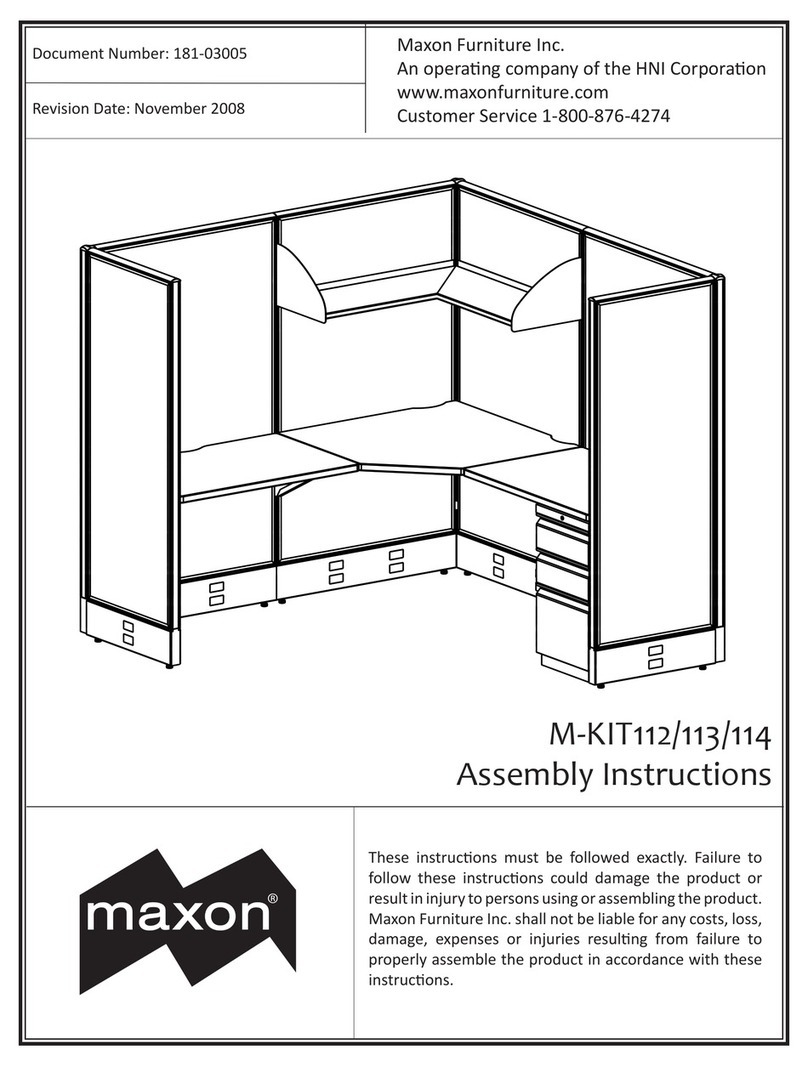
M-KIT118/119/120
Assembly Instructions
Document Number: 181-03007
Revision Date: November 2008
®
Maxon Furniture Inc.
An operang company of the HNI Corporaon
www.maxonfurniture.com
Customer Service 1-800-876-4274
These instrucons must be followed exactly. Failure to
follow these instrucons could damage the product or
result in injury to persons using or assembling the product.
Maxon Furniture Inc. shall not be liable for any costs, loss,
damage, expenses or injuries resulng from failure to
properly assemble the product in accordance with these
instrucons.

Page 2 of 11 M-KIT118/119/120 Assembly Instrucons 181-03007
These instrucons must be followed exactly. Failure to follow these instrucons could damage the product or result in injury to persons
using or assembling the product. Maxon Furniture Inc. shall not be liable for any costs, loss, damage, expenses or injuries resulng from
failure to properly assemble the product in accordance with these instrucons.
Maxon Furniture Inc. Customer Service: 1-800-876-4274
Quanty Part Number Descripon
8PL4848 Raceway Panel, 48H x 48W
3PLCP48 Raceway Corner Post, 48” High
2UWR2448TM Rectangular Worksurface, 24D x 48W*
2UWR2448TM-NC Rectangular Worksurface, 24D x 48W, No Canlevers
4 LLSR48 Spanner Rail, 48”
6 EC1E Raceway End Cover, 6” High
* The Worksurface cartons contain one Right-hand and one Le-hand Canlever screwed to the worksurface.
For installaon assistance or to report missing parts, please contact Customer Service at 1-800-876-4274
PL4848
PLCP48
EC1E
LLSR48
UWR2448TM UWR2448TM-NC

Page 3 of 11 M-KIT118/119/120 Assembly Instrucons 181-03007
These instrucons must be followed exactly. Failure to follow these instrucons could damage the product or result in injury to persons
using or assembling the product. Maxon Furniture Inc. shall not be liable for any costs, loss, damage, expenses or injuries resulng from
failure to properly assemble the product in accordance with these instrucons.
Maxon Furniture Inc. Customer Service: 1-800-876-4274
Tools Required for Assembly
Hardware Kits
Please ensure all required pieces are present before beginning assembly. Some steps may require a second
person for assembly assistance.
Panel Hardware (PL4848)
Rectangular Worksurface Hardware (UWR2448TM)
Phillips Screwdriver
Level
Drill/Screw Gun
with Phillips bit
Boxcuer
Tape Measure
1/2” Box End or
Adjustable Wrench
Wire Cuers
or Snips
End Cap
Provided: 8
Used: 6
Top Cap Spacer
Provided: 8
Used: 2
I-Beam Panel Connector
Provided: 48
Used: 48
#8 x 1/2" Phillips Flat Head
Provided: 16
Used: 0
Straight Alignment Bracket
Provided: 8
Used: 0
Lock Bar
Provided: 8
Used: 0
Provided: 4
Used: 0
Corner Bracket - RH
Provided: 4
Used: 0
Corner Bracket - LH
Provided: 4
Used: 0
#10 x 3/4" Panhead Screw
Provided: 64
Used: 12

Page 4 of 11 M-KIT118/119/120 Assembly Instrucons 181-03007
These instrucons must be followed exactly. Failure to follow these instrucons could damage the product or result in injury to persons
using or assembling the product. Maxon Furniture Inc. shall not be liable for any costs, loss, damage, expenses or injuries resulng from
failure to properly assemble the product in accordance with these instrucons.
Maxon Furniture Inc. Customer Service: 1-800-876-4274
Hardware Kits
Corner Post Hardware (PLCP48)
Spanner Rail Hardware (LLSR48)
#10 x 3/4" Panhead Screw
Provided: 8
Used: 8
Spanner Clip
Top Cap Spacer
Provided: 9
Used: 0
Straight Alignment Bracket
Provided: 3
Used: 3
I-Beam Panel Connector
Provided: 18
Used: 12
Raceway Corner End Cap
Provided: 3
Used: 0
Raceway 3-Way End Cap
Provided: 3
Used: 2
Brackets are shipped
in strips of 3 - break
apart before using.
Angle Alignment
Bracket
Provided: 9
Used: 7
Corner Post Cap
Provided: 3
Used: 3
Wedge Bracket
Provided: 9
Used: 9
Provi
d
e
d
:
8
Used
:
8

Page 5 of 11 M-KIT118/119/120 Assembly Instrucons 181-03007
These instrucons must be followed exactly. Failure to follow these instrucons could damage the product or result in injury to persons
using or assembling the product. Maxon Furniture Inc. shall not be liable for any costs, loss, damage, expenses or injuries resulng from
failure to properly assemble the product in accordance with these instrucons.
Maxon Furniture Inc. Customer Service: 1-800-876-4274
Installing the Panels Slide/pry the Top Cap from each PL4848 Panel, 1.
being careful not to damage the parts (Figure
1).
CAUTION! The following steps may
require assistance to complete.
Posion two PL4848 Panels in their 2.
approximate installed locaon and level
by turning the Glides on the boom of the
PL4848 Panel frame with a ½” wrench.
On one PL4848 Panel, insert one Straight 3.
Alignment Bracket into the notch located on
the Panel’s edge at the boom of the PL4848
Panel frame (Figure 2).
Place one PLCP48 Corner Post on top of the 4.
Straight Alignment Bracket.
Connect the PLCP48 Corner Post to the PL4848 5.
Panel by sliding the plasc I-Beam Panel
Connectors down the grooves in between the
PLCP48 Corner Post and the PL4848 Panel’s
edge (Figure 3).
TIP! You will need three I-Beam
Panel Connectors to ll each groove
(six per connecon).
Using wire cuers or snips, trim the excess 6.
I-Beam Panel Connector length so that the
grooves are completely lled and ush with
the Panel frame top.
Place one PL4848 Panel against the PLCP48 7.
Corner Post at a 90° angle from the rst
PL4848 Panel creang an L shape.
Insert one Angle Alignment Bracket (Figure 2 8.
and Figure 4 on next page) into the slots of the
two PL4848 Panels being connected.
TIP! Use two slots near the boom
to help eliminate interference with
future accessory installaons.
Panel end
Top Cap
Figure 2
Figure 3
I-Beam Panel Connectors
PLCP48
Corner Post
PL4848
Panel
PL4848
Panel
Exterior Assembly View
Corner Post
Angle Alignment
Bracket
Straight Alignment
Bracket
Glide
Top View
I-Beam Panel
Connectors
Figure 1

Page 6 of 11 M-KIT118/119/120 Assembly Instrucons 181-03007
These instrucons must be followed exactly. Failure to follow these instrucons could damage the product or result in injury to persons
using or assembling the product. Maxon Furniture Inc. shall not be liable for any costs, loss, damage, expenses or injuries resulng from
failure to properly assemble the product in accordance with these instrucons.
Maxon Furniture Inc. Customer Service: 1-800-876-4274
While holding the Angle Alignment Bracket 9.
(AAB) in place, connect the second PL4848
Panel by inserng the I-Beam Panel Connectors
as directed in Steps 5 - 6.
Connue adding PL4848 Panels and PLCP48 10.
Corner Posts in the order shown by inserng
Straight Alignment Brackets to support the
PLCP48 Corner Posts (Figures 5.a - 5.h).
TIP! You will need three Straight
Alignment Brackets total.
Install one Angle Alignment Bracket with each 11.
PL4848 Panel added.
TIP! You will need seven Angle
Alignment Brackets total.
Insert I-Beam Panel Connectors for all PLCP48 12.
Corner Post to PL4848 Panel connecons as
directed in steps 5 - 6.
Figure 5
Figure 5.a
Angle Alignment Bracket (AAB)
Straight
Alignment
Bracket
Corner
Post
Figure 5.b
Figure 5.c
AAB
Figure 5.d
AAB
Figure 4
Angle
Alignment
Bracket
Interior Assembled View
Figure 5.e
AAB
Straight
Alignment
Bracket
Corner
Post
Figure 5.f
Figure 5.g
AAB
Figure 5.h
AAB

Page 7 of 11 M-KIT118/119/120 Assembly Instrucons 181-03007
These instrucons must be followed exactly. Failure to follow these instrucons could damage the product or result in injury to persons
using or assembling the product. Maxon Furniture Inc. shall not be liable for any costs, loss, damage, expenses or injuries resulng from
failure to properly assemble the product in accordance with these instrucons.
Maxon Furniture Inc. Customer Service: 1-800-876-4274
Installing the Raceway Trim Pull down one Raceway Cover on each PL4848 1.
Panel (except Panels 1 & 2) by gently pulling
on the top of the Raceway Covers.
Install one EC1E Raceway End Cover onto the 2.
exposed end of each PL4848 Panel on the
inside of the Raceway Cover (Figure 6).
TIP! You will need six EC1E Raceway
End Covers total.
Install one 3-Way End Cap at each end of the 3.
assembly (Figure 7).
TIP! You will need two 3-Way End
Caps total. The bent tab of the 3-Way
End Cap should be placed against
the PLCP48 Corner Post.
Close the Raceway Covers.4.
Raceway Cover
1
2
EC1E
Raceway End Cover
Tab at top
EC1E
Raceway End Cover
Raceway Cover
3-Way End Cap
Bent tab
at top
Figure 7
Figure 6

Page 8 of 11 M-KIT118/119/120 Assembly Instrucons 181-03007
These instrucons must be followed exactly. Failure to follow these instrucons could damage the product or result in injury to persons
using or assembling the product. Maxon Furniture Inc. shall not be liable for any costs, loss, damage, expenses or injuries resulng from
failure to properly assemble the product in accordance with these instrucons.
Maxon Furniture Inc. Customer Service: 1-800-876-4274
Install one Wedge Bracket at each of 1.
nine PL4848 Panel to PLCP48 Corner Post
connecons by inserng the Wedge Bracket
between the Panel and the Corner Post
(Figures 8 and 9.a).
TIP! No Wedge Bracket is
needed between Panel 1 and the
PLCP48 Corner Post at the 4-way
connecon.
Install one Corner Post Cap on each of three 2.
PLCP48 Corner Posts (Figure 9.a).
Install one Top Cap Spacer into each of two 3.
Top Caps (Figure 9.b).
Install the Top Caps with Spacers onto Panels 4.
1 and 2.
Install one End Cap into each of the six 5.
remaining Top Caps (Figure 9.c).
Install the Top Caps onto the PL4848 Panels. 6.
TIP! The End Cap tab should t into
the PL4848 Panel frame.
Installing The Top Trim
Figure 9
Figure 8
3-Way
Connection
Wedge
Brackets
12
End Cap
(6 places)
Top Cap Spacer
Figure 9.b
End Cap
Figure 9.c
Corner Post Cap
Wedge Bracket
Figure 9.a

Page 9 of 11 M-KIT118/119/120 Assembly Instrucons 181-03007
These instrucons must be followed exactly. Failure to follow these instrucons could damage the product or result in injury to persons
using or assembling the product. Maxon Furniture Inc. shall not be liable for any costs, loss, damage, expenses or injuries resulng from
failure to properly assemble the product in accordance with these instrucons.
Maxon Furniture Inc. Customer Service: 1-800-876-4274
Installing the Spanner Rails Unpack the LLSR48 Spanner Rail.1.
Hook the two Spanner Clips onto the top 2.
ange of the LLSR48 Spanner Rail (Figure 10).
Posion the LLSR48 Spanner Rail into the 3.
Panel slots at about 28” from the oor to the
top of the Rail.
With the LLSR48 Spanner Rail lted upward 4.
about 45°, slide the top tooth into the PL4848
Panel slot, then rotate the LLSR48 Spanner
Rail down to engage the other teeth.
Repeat steps 1 - 4 to install the three remaining 5.
LLSR48 Spanner Rails into the outer PL4848
Panels.
Figure 10
28"
Spanner
Rail
Spanner
Rails
(hidden)
Spanner
Clips
Spanner Rail

Page 10 of 11 M-KIT118/119/120 Assembly Instrucons 181-03007
These instrucons must be followed exactly. Failure to follow these instrucons could damage the product or result in injury to persons
using or assembling the product. Maxon Furniture Inc. shall not be liable for any costs, loss, damage, expenses or injuries resulng from
failure to properly assemble the product in accordance with these instrucons.
Maxon Furniture Inc. Customer Service: 1-800-876-4274
Unpack the four UWR2448TM Rectangular 1.
Worksurfaces.
TIP! Only two worksurfaces will
have a Le-hand Canlever Bracket
and a Right-hand Canlever Bracket
aached.
Unscrew the Canlever Brackets from the 2.
worksurfaces.
Posion a Right Hand Canlever Bracket into 3.
the Panel slots at the same height as the
Spanner Rails (Figure 11).
With the Canlever lted upward about 45°, 4.
slide the top tooth into the PL4848 Panel slot,
then rotate the Canlever down to engage the
other teeth (Figure 12).
Repeat steps 3 - 4 to install the remaining 5.
Canlever Brackets into the PL4848 Panels
(Figure 13).
Place a UWR2448TM Worksurface into 6.
posion on a Canlever Bracket and LLSR48
Spanner Rail.
Conrm that this is the desired worksurface 7.
height and reposion the Canlever Brackets
and LLSR48 Spanner Rails, if necessary.
Installing the Worksurfaces
Figure 13
Figure 12
Figure 11
28"
Right Hand
Cantilver Bracket
22"
Approx.
Top View
Right Hand
Cantilever
Right Hand
Cantilever Left Hand
Cantilever
Left Hand
Cantilever
Spanner Rail
Spanner Rail
Spanner
Clips

Page 11 of 11 M-KIT118/119/120 Assembly Instrucons 181-03007
These instrucons must be followed exactly. Failure to follow these instrucons could damage the product or result in injury to persons
using or assembling the product. Maxon Furniture Inc. shall not be liable for any costs, loss, damage, expenses or injuries resulng from
failure to properly assemble the product in accordance with these instrucons.
Maxon Furniture Inc. Customer Service: 1-800-876-4274
With the Spanner Clips near the front and 8.
back edges of the Rectangular Worksurface
(about 22” apart), aach the Spanner Clips
to the Rectangular Worksurface using one
#10 x ¾” Panhead Screw in each Spanner Clip
(Figure 14).
Aach the Canlever to the Rectangular 9.
Worksurface with three #10 x ¾” Panhead
Screws.
Repeat steps 6 - 9 for the other three 10.
Rectangular Worksurfaces.
#10 x 3/4" Panhead Screw
(2 in each Spanner Rail,
3 in each Cantilever for
a total of 20)
Figure 14
This manual suits for next models
2
Table of contents
Other Maxon Indoor Furnishing manuals
Popular Indoor Furnishing manuals by other brands

Sauder
Sauder Camden 101730 Instruction booklet

Lightolier
Lightolier Lighting Systems LP-16 Specification sheet

Furniture of America
Furniture of America CM3487T Assembly instructions

Home Styles
Home Styles 6661-80 quick start guide

SitOnit Seating
SitOnit Seating Parallon Assembly instructions

MARCKERIC
MARCKERIC 2P1C Assembly instructions