Maxtec MaxVenturi R211P03 User manual

OPERATING MANUAL &
INSTRUCTIONS FOR USE
R211M03 Rev. Q
R211P03
MaxVenturi
A
B
C
D
E
F60
50
40
30
20
10
0
2
®


I866.4.Maxtec www.maxtec.com
EC REP
Maxtec TEL (800) 748.5355
2305 South 1070 West FAX (801) 973.6090
USA website: www.maxtec.com
Authorized Representative:
QNET BV
Kantstraat 19
NL-5076 NP Haaren
The Netherlands
CLASSIFICATION
Protection against electric shock: ..........................Internally powered equipment.
Protection against water: ....................................................IPX1
Mode of Operation: ...................................................Continuous
Sterilization: ......................................................See section 7.0
Flammable anesthetic mixture: . . . . . . . . . . . . . . . . . . . . . . . Not suitable for use in presence of a
flammable anesthetic mixture
Product Disposal Instructions:
The sensor, batteries, and circuit board are not suitable for regular trash disposal. Return
sensor to Maxtec for proper disposal or dispose according to local guidelines. Follow local
guidelines for disposal of other components.
WARRANTY
Provided the device is properly maintained and under normal operating conditions,
Maxtec warrants the MaxVenturi to be free from defects of workmanship or materials
for a period of 2 years from the date of shipment from Maxtec. Based on Maxtec’s
product evaluation, Maxtec’s sole obligation under the foregoing warranty is limited to
making replacements, repairs, or issuing credit for equipment found to be defective.
This warranty extends only to the buyer purchasing the equipment directly from Maxtec
or through Maxtec’s designated distributors and agents as new equipment.
Maxtec warrants the MAX-250E oxygen sensor in the MaxVenturi to be free from
defects in material and workmanship for a period of 2 years from Maxtec’s date of
shipment in a MaxVenturi unit. Should a sensor fail prematurely, the replacement
sensor is warranted for the remainder of the original sensor warranty period.
Routine maintenance items, such as batteries, are excluded from warranty. Maxtec
and any other subsidiaries shall not be liable to the purchaser or other persons for
incidental or consequential damages or for equipment that has been subject to abuse,
misuse, misapplication, alteration, negligence or accident.
These warranties are exclusive and in lieu of all other warranties, expressed or
implied, including warranty of merchantability and fitness for a particular purpose.

II 866.4.Maxtec www.maxtec.com
WARNINGS
!
Indicates a potentially hazardous situation, if not avoided, could result in death or serious injury.
» This device is not intended for use with life supporting devices/systems.
» Failure to comply with the warnings and precautions in this manual could result in
instrument damage and possibly jeopardize the wellbeing of the patient and/or health care
professional. Improper use of this device can cause inaccuracy of flow and oxygen readings
which can lead to improper treatment, hypoxia or hyperoxia, or other patient injury or
discomfort. Follow the procedures outlined in this user manual.
» Not for use in an MRI environment.
» If the O2% drifts away from the level to which it was set, check to make sure the nasal prongs
on the patient interface are not occluded by sputum or the nasal septum. Flow restriction to the
circuit or patient interface will cause the oxygen level to increase. Flow restriction downstream of
the venturi unit will not be detected by the flow meter.
» This device does not have any alarms for interruption in oxygen supply.
» Allow oxygen reading to stabilize before adjusting oxygen content.
» This device does not have any alarms for oxygen level high or low alarms.
» Never allow excess length of tubing near the patient’s head or neck which could result in strangulation.
» Use only Maxtec replacement sensors. Use of any other sensor will void warranty and may lead
to product damage, product malfunction, improper treatment to patient, hypoxia, or hyperoxia.
DO NOT use this device near any type of flame or flammable/explosive substances, vapors or
atmosphere. Operating the oxygen analyzer in these environments may result in fire or explosion.
» This device in its entirety (including electronics) is not suitable for use in the presence of
flammable anaesthetic mixtures or in an atmosphere of explosive gases. Operating the oxygen
analyzer in these environments may result in fire or explosion.
DO NOT attach a humidifier or any other source gas to the room air inlet. It should be occupied
at all times by the filter listed in the disposables list. The inlet filter prevents
entrainment of ambient contamination and silences venturi noise. The filter provided with the
MaxVenturi is single-patient use only.
» Use of this device with a pressurized oxygen bottle may result in inaccurate oxygen
concentration readings when used above 40 LPM and at high oxygen concentrations. High tank
pressures result in cooling oxygen supply temperatures which affect the accuracy of the oxygen
sensor. It is suggested that the device be connected with a long supply hose. Use a 15 ft supply
hose where possible — Maxtec P/N (R127P35).
» Use patient circuits that are approved for use with the manufacturer’s humidifier as listed in
their individual instructions for use.
DO NOT attempt to clean the inside of the flow meter. If any malfunction is detected in the
function of the flow meter, if any debris or contamination is detected in the flow meter, or if the float
sticks in the flow tube, discontinue use immediately and return the device to Maxtec for service.
» Never install the sensor in any location other than the sensor port in the device.
SENSOR WARNINGS: The Maxtec MAX-250 oxygen sensor is a sealed device containing a mild
acid electrolyte, lead (Pb), and lead acetate. Lead and lead acetate are hazardous waste constituents
and should be disposed of properly, or returned to Maxtec for proper disposal or recovery.
DO NOT use ethylene oxide sterilization.
DO NOT immerse the sensor in any cleaning solution, autoclave or expose the sensor to high
temperatures.
» Dropping or severely jarring the sensor after calibration may shift the calibration point enough to
require recalibration.
CAUTION: Indicates a potentially hazardous situation, if not avoided, could result in minor or
moderate injury and property damage.
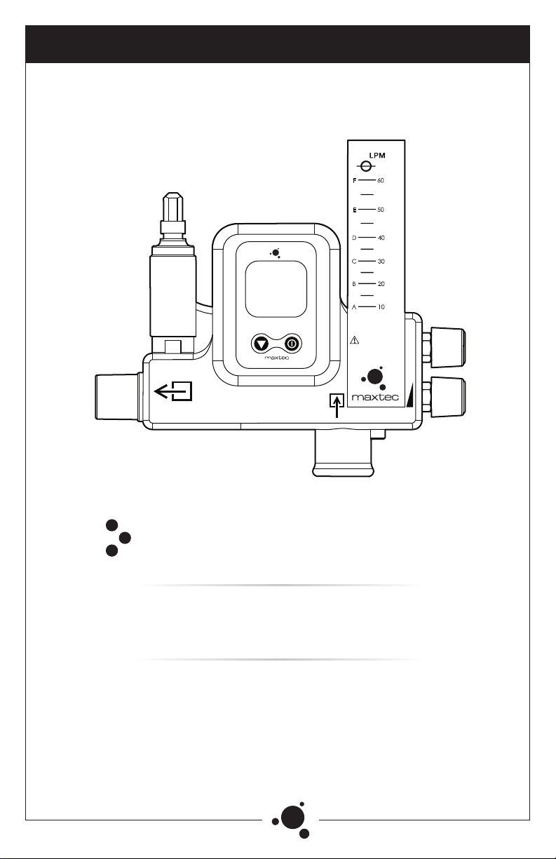
» The MaxVenturi is intended for use with specific patient interface configurations. The numbered scale
is intended for use with Fisher & Paykel* heated humidifier (MR850) and the Optiflow high flow patient
interface system (OPT846, OPT570) and Comfort Flo® Circuits (2415 & 2416) with the Hudson RCI®
Neptune®Heated Humidifier (425-00). The lettered scale (Labeled A through F) is intended for the
alternate patient circuits found on the chart provided in Section 2.

III866.4.Maxtec www.maxtec.com
» Never install the sensor in a location that will expose the sensor to patient exhalation or secretions.
» Only use Maxtec approved accessories and replacement parts. Failure to do so may seriously
impair the MaxVenturi’s performance. Repair or alteration of the MaxVenturi beyond the scope
of the maintenance instructions or by anyone other than authorized Maxtec service personnel
could cause the product to fail to perform as designed.
» Use of the MaxVenturi near devices that generate strong electrical fields may cause erratic readings.
» This device has a visual low-battery alarm but no audible alarm.
» Calibrate the MaxVenturi weekly when in operation or if environmental conditions change significantly,
i.e., Temperature, Humidity, Barometric Pressure. (refer to Calibration sections of this manual).
» The device will assume a percent oxygen concentration when calibrating. Be sure to apply
100% oxygen or room air concentration to the device during calibration or the device will not
calibrate correctly. (See section 2.2)
DO NOT use ethylene oxide sterilization. DO NOT immerse the device in any cleaning solution,
autoclave or expose the device to high temperatures.
» Use with any other patient interface system may result in false readings from the flow meter.
» The MaxVenturi is not intended for steam, ethylene oxide or radiation sterilization.
DO NOT clean with ethanol or acetone.
» After cleaning, and before use on a patient, attach the device to an oxygen supply and allow the
device to run at high flow for several minutes to allow any cleaning fluids or vapors to evaporate
and be flushed out.
» The device can flow excess oxygen out the entrainment port if the oxygen control knob is
turned up too high. This can lead to a minor drop in total air flow to the patient and excess
oxygen entering the room environment.
» Federal Law (USA) restricts this device to sale by or on the order of a physician.
ATTENTION: Indicates a potentially hazardous situation, if not avoided, could result in minor or
moderate injury and property damage.
» If the MaxVenturi is ever exposed to liquids (spills or immersion) or to any other physical abuse,
return to Maxtec for evaluation before use.
» Always remove the batteries to protect the unit from potential leaky battery damage when the
unit is going to be stored or not in use for periods exceeding 1 month. Replace dead batteries
with high quality AA Alkaline batteries.
DO NOT use rechargeable batteries with this device.
» Maxtec cannot warranty any damage resulting from misuse, unauthorized repair or improper
maintenance of the instrument.
» This product is Latex free.
» Avoid usage in environments with greater than 95% relative humidity.

IV 866.4.Maxtec www.maxtec.com
TABLE OF CONTENTS
Classification .................................................. I
Warranty ..................................................... I
Warnings .....................................................II
1.0 SYSTEM OVERVIEW ..........................................1
1.1 Component Identification .........................................1
1.2 Symbol Guide ..................................................2
1.3 Product Primary Functions ........................................2
2.0 SET-UP INSTRUCTIONS .......................................3
2.1 Sensor Installation...............................................3
2.2 Calibration ....................................................3
2.2.1 Room Air Calibration ...........................................4
2.2.2 100% Oxygen Calibration .......................................4
2.3 Device Set-up ..................................................5
2.4 Flow and Oxygen Adjustment ......................................6
2.4.1 Initial Settings ................................................6
2.4.2 Changing Flow Settings .........................................6
2.4.3 Changing Oxygen Settings .......................................7
2.5 Disposables ...................................................7
2.5.1 Disposable Patient Circuits.......................................7
2.5.2 Disposable Patient Interfaces .....................................7
2.5.3 Inlet Filter ...................................................9
3.0 FACTORS INFLUENCING ACCURATE READINGS .....................9
3.1 Elevation/ Pressure Changes .......................................9
3.2 Temperature Effects .............................................9
4.0 CALIBRATION ERRORS AND ERROR CODES ........................9
5.0 CHANGING THE BATTERIES...................................10
6.0 CHANGING THE OXYGEN SENSOR ..............................11
7.0 CLEANING AND MAINTENANCE ................................11
7.1 Routine Maintenance ...........................................11
7.2 Device Cleaning ...............................................11
7.3 Oxygen Sensor Cleaning .........................................11
8.0 SPECIFICATIONS ...........................................12
8.1 Analyzer Specifications ..........................................12
8.2 Oxygen Diluter Specifications .....................................12
8.3 Oxygen Inlet Supply ............................................13
9.0 MAXVENTURI SPARE PARTS AND ACCESSORIES ...................13
9.1 Included with your Unit..........................................13
9.2 Standard Replacement Parts and Accessories.........................13
9.3 Other Replacement Parts and Repairs...............................13
9.4 Routine Maintenance ...........................................13
10.0 TROUBLESHOOTING .......................................14
11.0 AIR-ENTRAINMENT DEVICES VS BLENDERS .....................14

1866.4.Maxtec www.maxtec.com
1.0 SYSTEM OVERVIEW
1.1 Component Identification
60
50
40
30
20
10
O
2
7
89
13
14
12
11
10
Flow meter
Oxygen On/Off Valve
Inlet Oxygen Fitting
Oxygen % Control Knob: O2
Flow Control Knob:
Room Air Inlet:
Room Air Inlet Filter
ON/OFF Button:
Calibration Button:
MAX-250 Series Oxygen Sensor
Low Battery Indicator:
3.5-Digit Display
Calibration Needed Indicator:
Patient Outlet:
7
8
9
10
11
12
13
14
CAL
BAT

2866.4.Maxtec www.maxtec.com
BAT
1.2 Symbol Guide
The following symbols and safety labels are found on the MaxVenturi:
1.3 Product Primary Functions
The primary function of the MaxVenturi is to deliver a mixed gas of oxygen and air
to either a heated humidifier system or directly to a patient. One of the primary
accessories to the MaxVenturi is a Fisher & Paykel heated humidifier (MR850)
and the Optiflow high flow patient interface system and Comfort Flo®Circuits
(2415 & 2416) with the Hudson RCI®Neptune®Heated Humidifier (425-00).
Several other patient interface circuits listed in section 2.5 can also be used
with the MaxVenturi.
The MaxVenturi flow meter is labeled to compensate for the back pressure by
the humidifier/patient interface system.
» The numbered scale on the flow meter that corresponds to the compensated flow rate
for the Fisher & Paykel Optiflow System and Hudson RCI®Neptune®Heated Humidifier.
» The lettered scale on the flow meter corresponds to the flow rates for the other patient
interface circuits listed in the chart in Section 2.5
Warning
On/off Button
Calibration Required
Room Air Inlet
Calibration Button
Low Battery
Percent
ETL Classified conforms
to ULSTD 60601-1
Do not throw away. Follow local
guidelines for disposal.
Patient Outlet
Adjustable Flow
CAL
%
EC REP Authorized Representative
in the European Community
LOT
IPx1
SN
Lot code/Batch code
Drip Proof
Serial Number
REF
LPM
Catalog Number
Liter Per Minute Flow
Manufacturer
Follow instructions for use.
Do Not
Read Flow Meter Float
At Center
Federal Law (USA) restricts this device to
sale by or on the order of a physician
only
!

3866.4.Maxtec www.maxtec.com
2.0 SET-UP INSTRUCTIONS
2.1 Sensor Installation
2.2 Calibration
A new calibration is required when:
» The measured O2percentage in 100% O2is below 97.0%.
» The measured O2percentage in 100% O2is above 103.0%.
» The CAL reminder icon is blinking at the bottom of the LCD.
» You are unsure about the displayed O2percentage, see Factors Influencing Accurate
Readings in section 3.0.
The MaxVenturi can be calibrated at 100% oxygen or room oxygen (20.9%).
The One Touch calibration will assume one of these two concentrations.
On/off Button
Calibration Button
Low Battery
Percent
Authorized Representative
in the European Community
Lot code/Batch code
Drip Proof
Serial Number
Manufacturer
2
...30-90 Minutes
5
3
6
1
4
Remove Max-250 sensor
from package and pull
off barrier film.
Wait 30 to 90 minutes
for sensor to stabilize.
Attach flow diverter.
Attach sensor to sensor
cable.
Press and hold CAL button
for three (3) seconds.
Wait for display to read
"20.9%".
Insert sensor into port on
MaxVenturi.

4866.4.Maxtec www.maxtec.com
2.2.1 Room Air Calibration
CAUTION: Turn off all flow of gas to the MaxVenturi before calibration in room air.
Calibrating the oxygen sensor in a gas concentration other than room air (20.9%) will result
in an incorrect measurement of oxygen concentration.
2.2.2 100% Oxygen Calibration
2
6
2
...2 Minutes
1 2 3
4 5 6
7 8
...2 Minutes
1
5
Shut off Oxygen supply. Remove sensor from port. Wait two (2) minutesfor
sensor to equilibratein
room air.
Press and hold CAL button
for three (3)seconds. Wait
for display to ead "20.9%".
Place sensor in port.
Connect Oxygen supply. Plug room air inlet. Turn ON/OFF valve to
the ON position.

5866.4.Maxtec www.maxtec.com
NOTE: Analyzer will read "Cal Err St" if the sample gas is not stable or if the oxygen
sensor has reached its end of life.
2.3 Device Set-up
1 2 3
4 5 6
7 8
...2 Minutes
1 2 3
4 5 6
7 8
...2 Minutes
Turn flow knob a few
turns to flow gas.
Wait 2 minutes for
sensor to equilibrate.
Press and hold CAL
button for three (3)
seconds. Wait for display
to read 100%.
Remove plug from room
air inlet.
Insert filter into room air
inlet.
1 2 3
4 5
Attach MaxVenturi to
IV pole. Twist knob to
tighten.
Connect oxygen
supply line from wall to
MaxVenturi.
Insert air inlet filter in
room air inlet port.

6866.4.Maxtec www.maxtec.com
NOTE: Patient circuit and patient interface should be assembled according to
manufacturers instructions supplied with them.
2.4 Flow and Oxygen Settings Adjustment
2.4.1 Initial Settings
2.4.2 Changing Flow Settings
1 2 3
4 5
1
2
3
1
2
3
1
2
3
1
2
3
1 2
3
Adjust flow to new desired flow rate. Readjust oxygen concentration to desired
setting and wait for analyzer to equilibrate.
Temporarily disconnect patient circuit if
necessary.
Attach patient circuit to
MaxVenturi outlet.
Turn ON/OFF valve to on
position.
Adjust flow to desired
setting and read flow
meter.
Set desired oxygen mixture
by opening O2% knob and
read analyzer.
Adjust flow if it has
changed.

7866.4.Maxtec www.maxtec.com
2.4.3 Changing Oxygen Settings
Warning: Adjusting the oxygen setting too high at low flows may cause
oxygen to exit the air inlet port. Verify the direction of flow by placing your
hand under the air filter to feel for air escape.
2.5 Disposables
The MaxVenturi for is intended for use with approved disposables. Several patient
delivery circuits and patient interfaces have been tested and approved for use with
the MaxVenturi. The approved delivery circuits and patient interfaces are:
2.5.1 Disposable Patient Circuits
» Fisher & Paykel single heated limb circuit (RT202) with humidifier chamber (MR290).
» Airlife single heated limb circuit (RT600-850) with humidifier chamber (MR290).
» Standard 6', 22mm corrugated tube (Airlife 001450 or similar. Not humidified).
»Comfort Flo®Circuits (2415 & 2416) with the ConchaSmart®Column (382-10).
2.5.2 Disposable Patient Interfaces
» Optiflow large nasal cannula (Fisher & Paykel OPT544).
» Optiflow medium nasal cannula (Fisher & Paykel OPT846).
» Optiflow Tracheostomy direct connection (Fisher & Paykel OPT570).
» Pediatric aerosol mask with 22mm inlet (Airlife 001263 or similar).
» Adult aerosol mask (Airlife 001206 or similar).
» Trach adaptor T-piece (Airlife 001500 or similar).
» Tracheostomy mask with 22mm inlet - loose fitting (Airlife 001225 or similar).
» Hudson RCI® Trach-Flex™PlusTracheostomy Adapter (2415-01).
» Hudson RCI® Comfort Flo®Plus Cannula - Large (2412-11).
» Hudson RCI® Comfort Flo®Plus Cannula - Medium (2412-12).
» Hudson RCI® Comfort Flo®Plus Cannula - Small (2412-13).
CAUTION: Use of patient circuits or patient interfaces other than these constitutes
"off- label use". This can result in device malfunction or harm to the patient.
The delivery circuit can be paired with the patient interface circuits listed in
the table below:
1 2
1 2
!
Adjust O2% knob to desired level and
wait for analyzer to equilibrate.Temporarily
disconnect patient circuit if necessary.
Verify flow rate has not changed and
adjust if necessary.

8866.4.Maxtec www.maxtec.com
TABLE INSTRUCTIONS: To determine the desired flow, locate the patient
delivery circuit and interface in the two left-hand columns. Find the
corresponding flow rate by reading to the right under columns A through F.
The lettered columns correspond to the lettered graduations on the flow meter.
CAUTION: The flow rates listed in this table are the result of bench testing the MaxVenturi
on the indicated patient circuits and interfaces. Actual flows may vary in clinical use
depending on patients physiology, breathing rate and other factors listed in Section 3.0.
NOTE: For the Comfort Flo Humidification System, a section of 22mm tubing is used to
connect the outlet of the MaxVenturi to the inlet of the humidification chamber in place
of the supplied pressure relief valve.
F&P Humidifier with 22mm
Single Heated Limb Circuit
Hudson RCI®Trach-Flex™Plus Tracheostomy Adaptor (2415-01)
Hudson RCI®Comfort Flo®Plus Cannula - Large (2412-11)
Hudson RCI®Comfort Flo®Plus Cannula - Medium (2412-12)
Hudson RCI®Comfort Flo®Plus Cannula - Small (2412-13)
F&P Direct Connect (OPT570)
F&P Large Nasal Cannula (OPT846)
F&P Medium Nasal Cannula (OPT544)
F&P Small Nasal Cannula (OPT542)
Interface Patient
6' - 22mm Corrugated
Tube
Hudson RCI®Trach-Flex™Plus Tracheostomy Adaptor (2415-01)
Hudson RCI®Comfort Flo®Plus Cannula - Large (2412-11)
Hudson RCI®Comfort Flo®Plus Cannula - Medium (2412-12)
Hudson RCI®Comfort Flo®Plus Cannula - Small (2412-13)
F&P Direct Connect (OPT570)
F&P Large Nasal Cannula (OPT846)
F&P Medium Nasal Cannula (OPT544)
F&P Small Nasal Cannula (OPT542)
Interface Patient
Hudson RCI
®Neptune®
Heated Humidifier with
ConchaSmart
™Technology
and 15mm Comfort Flo
Humidification Circuit
(REF 2415 & 2416)

9866.4.Maxtec www.maxtec.com
2.5.3 Inlet Filter
» Air Safety Ltd. Cat.No. RP34P02
3.0 FACTORS INFLUENCING ACCURATE READINGS
3.1 Elevation/Pressure Changes
» Changes in elevation result in a reading error of approximately 1% of reading per 250 feet.
» A change in altitude greater than 500 ft will require sensor recalibration.
» This device does not automatically compensate for changes in barometric pressure
or altitude. If the device is moved to a location of a different altitude, it must be
recalibrated before use (see section 2.2).
3.2 Temperature Effects
The MaxVenturi will read correctly (within ±3%) when operating at thermal
equilibrium within the operating temperature range of 15 °C - 40 °C
(59 °F - 104 °F). The device must be thermally stable when calibrated and
allowed to thermally stabilize after experiencing temperature changes before
readings are accurate. For these reasons it is recommended to:
» Perform the calibration procedure at a temperature close to the temperature at which the
device will be operated.
» Allow adequate time for the sensor to equilibrate to a new ambient temperature.
ATTENTION: “CAL Err St” may result from a sensor that has not reached thermal equilibrium.
4.0 CALIBRATION ERRORS AND ERROR CODES
The analyzer has a self test feature built into the software to detect faulty
calibrations, oxygen sensor failures, and low battery voltage. The tests and
actions to take if an error occurs are:
E02: NO SENSOR ATTACHED
» Disconnect and reconnect sensor. Unit should perform an auto calibration and should
read 20.9%. If not, contact Maxtec Customer Service for possible sensor replacement.
E03: NO VALID CALIBRATION DATA AVAILABLE
» Make sure unit has reached thermal equilibrium.
» Perform calibration as described in this manual.
E04: BATTERY BELOW MINIMUM OPERATING VOLTAGE
» Replace batteries.
CAL Err St: O2SENSOR READING NOT STABLE
» Wait for displayed oxygen reading to stabilize when calibrating the device at 100% oxygen.
» Wait for unit to reach thermal equilibrium. NOTE: this can take up to one half hour if
the device is stored in temperatures outside the specified operating temperature range.
CAL Err lo: SENSOR VOLTAGE TOO LOW
» Repeat calibration routine as described in this manual. If unit repeats this error more
than three (3) times, contact Maxtec Customer Service.

10 866.4.Maxtec www.maxtec.com
CAL Err hi: SENSOR VOLTAGE TOO HIGH
» Repeat calibration routine as described in this manual. If unit repeats this error more
than three (3) times, contact Maxtec Customer Service.
CAL Err Bat: BATTERY VOLTAGE TOO LOW TO RECALIBRATE
» Replace batteries.
5.0 CHANGING THE BATTERIES
1 2 3
4 5 6
7 8 9
Turn off analyzer. Use screwdriver to
remove four (4) screws
in back of device.
Pull front cover off away
from unit.
Turn on analyzer to verify
power.
Reattach battery pack to
rear wall of cavity. Use
caution to not pinch wires
between cover and body
of device.
Re-attach front cover
with four (4) screws.
Remove battery pack
from rear wall of cavity.
Use caution with wires.
Remove two (2) depleted
batteries.
Ensure correct
orientation and install
two (2) new batteries.

11866.4.Maxtec www.maxtec.com
6.0 CHANGING THE OXYGEN SENSOR
NOTE: For new sensor installation, follow procedure for new sensor installation in section 2.1.
7.0 CLEANING AND MAINTENANCE
Store the MaxVenturi at a temperature similar to that of its daily use.
7.1 Routine Maintenance
Maxtec recommends the performance check listed in the MaxVenturi
Preventive Maintenance Manual be conducted prior to placing the MaxVenturi
into clinical use and periodically thereafter. If the MaxVenturi does not function
as described in the performance check, discontinue use of the device pending
service by trained technicians or contact your Maxtec distributor or Maxtec at:
2305 South 1070 West Salt Lake City, Utah 84119.
The MaxVenturi's flow and O2adjustment valves should be replaced as needed.
The full MaxVenturi device should be overhauled and serviced a minimum of every 4
years with R211P30-001 and R211P30-002 to replace all O-rings, valves and knobs.
7.2 Device Cleaning
When cleaning or disinfecting the exterior of the MaxVenturi, take appropriate
care to prevent any solution from entering the device. Do not immerse
device in fluids. MaxVenturi external surfaces may be cleaned using a cloth
moistened with 65-70% isopropyl alcohol/water solution or a germicidal wipe.
7.3 Oxygen Sensor Cleaning
Clean the sensor with a cloth moistened with 65-70% isopropyl alcohol/water solution.
» Maxtec does not recommend use of spray disinfectants because they can contain
salts which can accumulate in the sensor membrane and impair readings.
» The oxygen sensor is not intended for steam, ethylene oxide or radiation sterilization.
23
1
Turn off analyzer. Disconnect sensor from
sensor cable.
Remove sensor from
sensor port. Dispose of
sensor according to local
guidelines.

12 866.4.Maxtec www.maxtec.com
8.0 SPECIFICATIONS
8.1 Analyzer Specifications
Measurement Range:....................................................0-100%
Resolution: . . . . . . . . . . . . . . . . . . . . . . . . . . . . . . . . . . . . . . . . . . . . . . . . . . . . . . . . . . . . . 0.1%
Accuracy and Linearity: ..................1% of full scale at constant temperature, R.H. and
pressure when calibrated at full scale
Total Accuracy: .....................±3% actual oxygen level over full operating temp range
Response Time: ....................90% of final value in approximately 15 seconds at 23˚C
Warm-up Time: ................................................... None required
Operating Temperature: .....................................15˚C - 40˚C (59˚F - 104˚F)
Storage Temperature:.......................................-15˚C - 50˚C (5˚F - 122˚F)
Atmospheric Pressure:............................................ 800-1013 mBars
Humidity:................................................0-95% (non-condensing)
Power Requirements:..............................2 AA Alkaline batteries (2 x 1.5 Volts)
Battery Life: ..............................approximately 5000 hours with continuous use
Low Battery Indication:...................................."BAT" icon displayed on LCD
Sensor Type: .................................Maxtec MAX-250 series galvanic fuel cell
Expected Sensor Life:........................... > 1,500,000 O2percent hours minimum
(2-year in typical medical applications)
Dimensions:...............................7.3 x 6.6 x 5.3 (185mm x 167mm x 135mm)
Weight: .......................................................2.54 ibs (1.15kg)
Drift of Measurement: .....< +/-1% of full scale at constant temperature, pressure and humidity
8.2 Oxygen Diluter Specifications
Flow: . . . . . . . . . . . . . . . . . . . . . . . . . . . . . . . . . . . . . . . . . . . . . . . . . . . . . .10-55 LPM adjustable
Flow Accuracy:
FiO2Range:. . . . . . . . . . . . . . . . . . . . . . . . . . . . . . . . . . . . . . . . . . . . . . . . . . . . . . . . .32%-100%
Oxygen inlet supply pressure:. . . . . . . . . . . . . . . . . . . . . . . . . . . . . . . . . . . . . . . . . . . . 45-55 psig
Oxygen inlet filter (internal): . . . . . . . . . . . . . . . . . . . . . . . . . . . . . . . . . . . .45-90 micron pore size
Ambient air inlet filter: . . . . . . . . . . . . . . . . . . . . . . . . . . . . . . . . . . . . . . . . Single patient use filter
(see section 2.5 for appropriate filter details)
Nominal (LPM)
10 ±33%
Operating Range
Accuracy
20 ±18%
30 ±15%
40 ±11%
50 ±11%
60 ±9%

13866.4.Maxtec www.maxtec.com
8.3 Oxygen Inlet Supply
This device was designed for an oxygen inlet pressure of 3.5 bar (50psi).
Certain geographical areas use 4 bar (58psi) or 5bar (73psi) as the standard
piped oxygen distribution pressure. This device can be operated at these
pressures but the flow readings on the flow meter must be corrected for the
additional pressure. The table below gives correction factors for each flow
meter graduation indicating the percent increase in flow from nominal that will
result due to the increased inlet pressure at 4bar and 5bar.
9.0 MaxVenturi SPARE PARTS AND ACCESSORIES
9.1 Included With Your Unit
Part Number Item
R211P03 Adjustable Flow MaxVenturi Medical Unit with Sensor
R211M03 User’s Guide and Operating Instructions
R125P03-002 MAX-250E Oxygen Sensor
RP34P02 Air inlet filter
9.2 Standard Replacement Parts and Accessories
Part Number Item
R127P35 15’ coiled polyurethane oxygen hose with DISS ends.
9.3 Other Replacement Parts and Repairs
For repair or parts issues not specified in this manual refer to the MaxVenturi
service manual (R211M01), or the MaxVenturi preventative maintenance
manual (R211M02).
9.4 Preventative Maintenance
It is recommended by Maxtec that service personnel check the function of the
device once a year, or as needed. The MaxVenturi Preventative Maintenance
Manual will guide you through the process. It is available for free at
www.maxtec.com. Equipment in need of factory repair shall be sent to:
Maxtec
Customer Service Department 2305 South 1070 West
Salt Lake City, Utah 84119
(Include RMA number)
Nominal Flow
LPM
4 Bar
(% increase)
5 Bar
(% increase)
10 - A
20 - B
30 - C
40 - D
50 - E
13
9
7
6
5
34
24
18
16
13
60 - F 412

14 866.4.Maxtec www.maxtec.com
10.0 TROUBLESHOOTING
Problem: The flow does not reach 55LPM even with the flow valve wide open.
Possible Cause: The pressure of your piped oxygen supply in your hospital
may be low. Also check to see if the float in the flow meter is sticking. Tip the
unit back and forth. Ball should roll freely. If it seems to stick or hesitate, return
the unit to Maxtec for service. If you cannot detect the problem, contact the
Maxtec Service Department by calling the number listed in this manual. Do not
disassemble the device to try to detect an internal problem.
Problem: The oxygen level on the display does not reach 100%, even with the
oxygen control knob fully open.
Possible Cause: Check if the device needs to be calibrated. If you wish to
use the device at oxygen concentrations closer to 100% oxygen, it is best to
calibrate the device at 100% oxygen. Refer to the calibration section in this
manual and follow the 100% oxygen calibration routine. If this does not solve
the problem, contact the Maxtec Service Department.
Problem: The oxygen level displayed does not go as low as the level indicated
in the specifications, even with the oxygen control knob completely closed.
Possible Cause: It is very likely the device needs to be calibrated. Also check
to make sure the humidifier and patient delivery disposables are the correct
size and installed correctly with no kinking or occlusion. Check the air inlet
filter for moisture or dirt - replace if necessary. Valve cartridges may be worn;
perform leak test according to preventative maintenance procedure.
11.0 AIR-ENTRAINMENT DEVICES VS BLENDERS
There are basic differences in the operation of a venturi air-entrainment
device, such as the MaxVenturi, versus an air oxygen blender. Some of the
differences are listed in the chart below. Further information regarding the use
of these types of devices can be found in literature such as:
R. Wilkins et. al, Egan's Fundamentals of Respiratory Care, St. Louis: Mosby, 2003.
Maxtec recognizes that the condition of the patient should be the primary
factor in deciding which type of treatment is suitable for use.
MaxVenturi Air-oxygen Blender
FiO2 Range: 21-100%
Audible alarm for low gas pressure or differential
gas pressure
Flow is less compliant to downstream flow
resistance
Requires both oxygen and medical air supply
Flow: 0-120 LPM
Supports any size tubing
FiO2 Range: 32-100%
No low pressure gas alarms
Flow is compliant to downstream flow resistance
Requires only an oxygen supply
Flow: 0-60LPM
Requires large bore tubing
Table of contents
Other Maxtec Medical Equipment manuals
Popular Medical Equipment manuals by other brands

Ossur
Ossur REBOUND POST-OP KNEE Instructions for use

Medovations
Medovations CleanFreak 1200-01 Instructions for use and cleaning

MICROPOINT
MICROPOINT qLabs ElectroMeter Q-3 Pro quick start guide

OPED
OPED VACOCAST DIABETIC Leaflet

agiliti
agiliti Crosscare Eleganza 5 Quick reference guide

AGFA
AGFA DR 100e user manual

Carestream DENTAL
Carestream DENTAL CS 7600 user guide

Osstell
Osstell Beacon user manual

VNS Therapy
VNS Therapy SENTIVA M3000 Programmer Technical guide

Ergonomic products
Ergonomic products R3A1 Installation and operation manual

Gima
Gima MG8001-H instruction manual

Sorenson Medical
Sorenson Medical Ambulatory Infusion Therapy PCA Patient manual