Maxwell HRC10 User manual

HRC10
Rope/Chain Windlass

Owner Note:
Record your serial Number here.
Copyright: Maxwell Marine International Ltd. P103124_1.00 – 7/3/2012

Maxwell Marine International Ltd – HRC10 Series 1
INTRODUCTION
•
Read this manual thoroughly before installation and
using the windlass
. Failure to adhere to the correct
procedures, recommendations and guidelines
described in this Owner’s Manual may invalidate the
warranty.
• Correct selection of windlass together with correct
installation,
care in use and maintenance, are
essential for long life and reliable performance.
•
In addition to this instruction manual, the following
components should be included with the windlass:
•Clutch Handle
•Deckplate Gasket
•Deck Cutout Details (at rear of manual)
•Deck stud Kit
- Studs
- Nuts
- Flat washers
- Spring washers
The following accessories may be required to
complete your installation:
•Remote up/down control panel
•Circuit breaker/isolator panel
•12V or 24V reversing solenoid
IMPORTANT INFORMATION
•The windlass must have a minimum pull capacity of
three times the combined weight of the anchor and
rope/chain.
•Keep hands, feet, loose clothing and hair well clear of
the windlass and rope/chain during operation.
•Never operate the windlass from a remote station
without having a clear view of the windlass.
•Do NOT use the windlass as a mooring point. When
anchoring or mooring, secure the line directly to a
bollard or deck cleat.
•
Do NOT use the windlass to pull the boat forward
when raising the
anchor. Use the boat's engine to
drive the boat up to the anchor.
•Do NOT attempt to break free a fouled anchor with the
windlass. Secure the line to a bollard or cleat and use
the boat's engine to break the anchor out.
•Always firmly tie down the anchor when under way or
in heavy seas. Do not rely on the windlass as a
securing device.
•Always turn the circuit breaker/isolator switch off when
the windlass is not in use and before you leave the
boat.
•Do NOT use the windlass to haul a person up a mast.
ROPE AND CHAIN SELECTION
Correct fit of rope and chain to chainwheel is essential for
the windlass to operate properly.
The ground tackle should be selected taking into account:
a) Boat size, displacement and windage.
b) Conditions of operation such as maximum depth of
water, type of bottom and likely weather conditions.
c) Holding power and size of anchor, taking special note
of the manufacturers’ recommendations.
Selection of chainwheel:
Part Number P103315 for :
HRC10-8: 14mm (9/16”)-16mm (5/8”) rope / 8mm (5/16”)
chain
Part Number P103316 for :
HRC10-10: 14mm (9/16”)-16mm (5/8”) rope / 10mm (3/8”)
chain
INSTALLATION
•For
automatic operation to be possible, the anchor
must be self launching.
•Tie the end of the anchor rope/chain to a secure
fixture in the rope/chain locker.
Foredeck layout
Ensure the deck is flat, if not; a plinth (A) will be required to
ensure the windlass sits on a flat surface.
A
Required clearances
Identify any bulkheads, wiring or piping under the deck that
should be avoided.
Position the
windlass so the rope/chain falls directly into
the rope/chain locker with at least
200mm (8”)
unobstructed fall.

2 Maxwell Marine International Ltd – HRC Series
Aligning the windlass
The windlass must be positioned to allow the rope/chain to
have a clear run from the bow roller (B) to the chainwheel
without deflection.
The windlass must be mounted pointing in the direction of
the incoming rope/chain
. This arrangement allows the
rope/chain to have maximum engagement with the
chainwheel.
B
B
Installation Procedure
Use the Deck Cutout Detai
ls drawing, as a guide for
marking and cutting the holes.
Tip: On GRP boats, running the drill in reverse first will
reduce chipping of the gel coat.
Using hole saws, cut the holes for the rope/chain pipe and
electrical cables.
On GRP or wooden decks, seal the edges of the holes
with epoxy to avoid ingress of moisture.
Install deck studs to windlass and tighten by use of two
nuts. Place the gasket onto the windlass and fit to deck.
Fasten the windlass to the deck usin
g the nuts and
washers supplied. Tighten the nuts progressively and
evenly. Do NOT use power tools. Make sure the
installation is firm, but do not over tighten the nuts.
Important note to Boat Builders
Experience has shown that, on long ocean deliveries as
deck cargo, sulphur from the ships exhaust and
condensation can damage the chrome plating and
stainless steel of the windlass.
We recommend, after completing installation, you spray
the top works of the windlass with CRC 3097 “long life” (or
alternative)
and wrap the windlass with plastic film and
tape.
WIRING INSTRUCTIONS
Installation must be carried out in accordance with USCG,
ABYC, NMMA, CE or other relevant
local electrical
requirements.
We recommend that connection of the power lines and
control circuitry to the windlass be done by qualified
technicians, to ensure reliable and safe operation of the
windlass.
After all connections have been made and system tested,
seal terminals against moisture by spraying with:
CRC2043 “Plasti-Coat”, CRC3013 “Soft Seal” or CRC2049
“Clear Urethane” (or alternative).
Solenoid pack (Required)
The solenoid pack (B)
should be located in a dry area
close to the windlass, not in the rope/chain locker.
Circuit breaker/isolator (Required)
! FOR SAFETY - The winch circuit requires
protection provided by an isolator switch and
either a fuse or circuit breaker, rated as follows:
HRC10-12V : 135amp
HRC10-24V : 80amp
Position the circuit breaker/isolator (C) no further than 1.8
m (6 ft) away from the battery (D) in an accessible and dry
location.
Remote control panel (Recommended)
The remote control panel (E)
should be mounted in a
convenient location (such as the bridge, helm or cockpit)
so that the operator can see the windlass.
Footswitch (Optional).
For
safe operation, the footswitch (F) should be
approximately 500 mm (20") from the windlass (A).
The below-deck part of the footswitch must be in a dry
environment and the breather holes must be kept clear.
The arrows on the footswitch should be
arranged to
indicate the direction of operation.
Fit the
switch according to the instructions supplied.
Connect wiring as shown.
Motor
When tightening the cables to the motor, ensure the lower
nut (A) is secure against turning when tightening the upper
nut (B). This will prevent damage occurring within the
motor.
A B

Maxwell Marine International Ltd – HRC10 Series 3
OPERATION
CAUTION:
Make sure that you do not operate the footswitch
accidentally while putting extra turns on the capstan.
Keep your fingers clear of the chainwheel and/or capstan.
When operating the windlass:
-
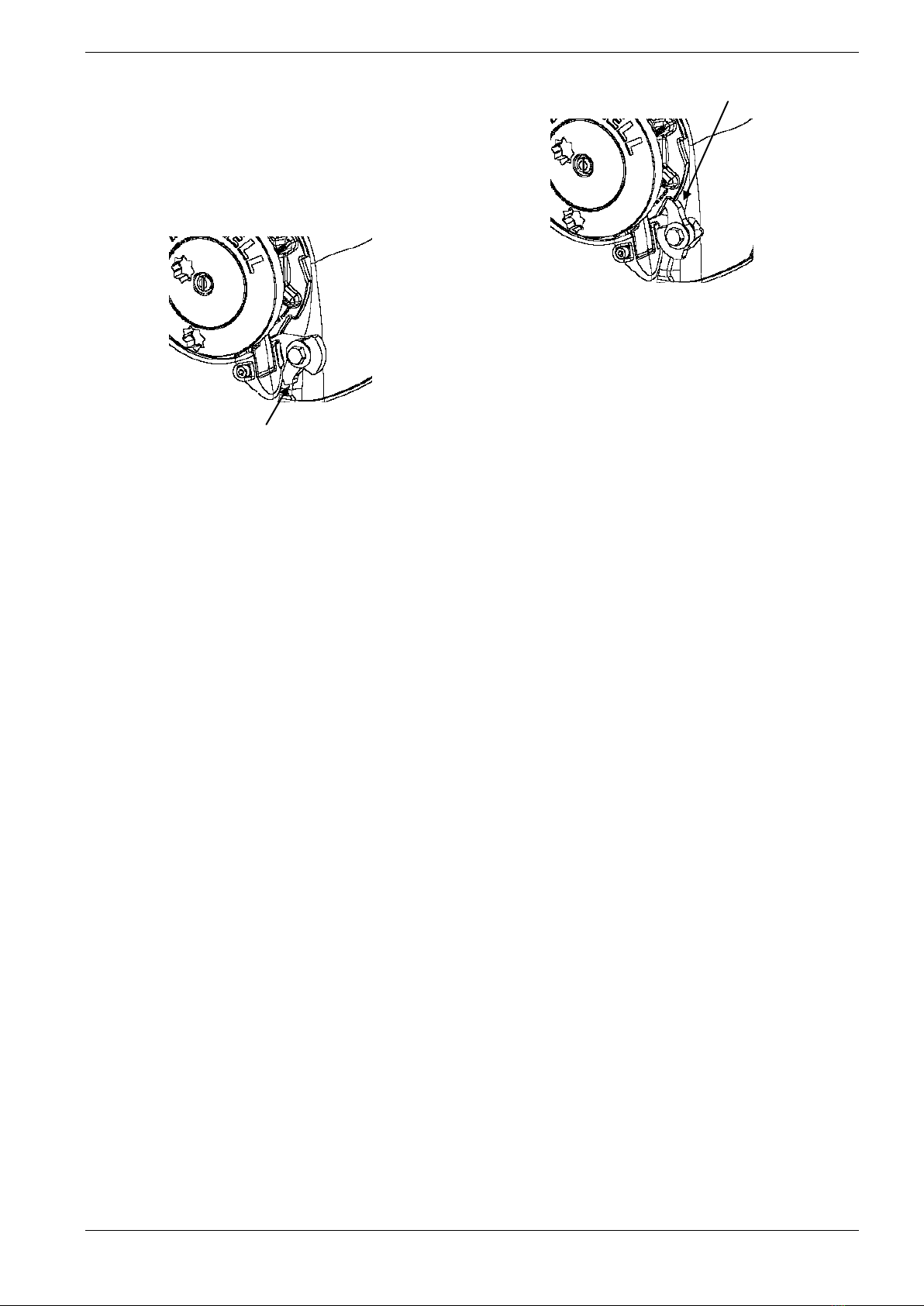
Ensure the pawl is in the disengaged position when
paying out the anchor.
Pawl In Disengaged position
-Do not switch immediately from one direction to the other.
Wait for the windlass to stop in one directio
n before
applying power in the other direction.
-
Run the boat’s motor(s) at sufficient rpm to activate the
charging system.
Always make sure the isolator switch is turned off when
the system is not being used.
Lowering the Anchor
Insert the clutch handle into the clutch nut and tighten the
clutches by turning the nut clockwise. Only tighten
sufficiently so that you can easily pull up the anchor.
REMOVE THE CLUTCH HANDLE.
Operate the windlass by pressing the toggle switch down
on the remote up/down control panel to pay out the
rope/chain (or press the "Down" footswitch if fitted).
Pay out sufficient rope/chain to set the anchor.
Watch as the rope/chain is being fed out. Any jam might
cause damage to the windlass.
Raising the Anchor
Insert the clutch handle into the clutch nut and tighten the
clutches by turning the nut clockwise. Only tighten
sufficiently so that you can easily pull up the anchor.
REMOVE THE CLUTCH HANDLE. NOTE: Over tightening
the clutches can cause damage to the motor when docking
the anchor.
Operate the windlass by pressing the toggle switch up on
the remote up/down control panel (or press the "Up"
footswitch if fitted).
Motor up to the anchor while retrieving it. Do not use the
windlass to pull the boat to the anchor.
To avoid damaging the bow fitting, retrieve the last meter
(3’) of rope/chain slowly and take care when docking the
anchor.
Note: To avoid applying the full force of the windlass to the
bow fitting when docking the anchor, adjust the clutch nut
so that there is some slippage when docking the anchor.
Free falling the Anchor
Insert the clutch handle into the clutch nut and loosen by
slowly turning the handle anticlockwise.
Tightening the clutch nut clockwise will control the rate of
descent.
CAUTION: Do not
allow the chainwheel to free wheel
uncontrolled as this will allow dangerously high speeds to
build up.
Raising the Anchor Manually:
Move the pawl into the engaged position.
Insert the clutch handle into the clutch nut and turn
anticlockwise to loosen the clutch. Note the chain wheel
may pay out the anchor until the pawl
locks into the
chainwheel.
Insert the clutch handle into the outer bi-square of the
chainwheel and rotate anticlockwise to pull in the line. A
bi-square to ½” socket adator has been provided with your
windlass. This can be used with any ½” ratchet to recover
the rode.
Using the Capstan Drum for Rope Warping:
The capstan can be used independently from the
chainwheel. This is ideal for handling mooring or docking
lines, or retrieving a second anchor. For safety reasons, a
footswitch is highly recommended.
To haul in using the capstan:
Make sure the anchor is secured.
Insert the clutch handle into the clutch nut and turn
anticlockwise until rotation stops. This will release the
mechanism so that the chainwhe
el remains stationary
while you operate the capstan.
Take three turns of rope around the drum in a clockwise
direction.
While holding the tail of the rope, press the "Up"
footswitch. The capstan will rotate clockwise.

4 Maxwell Marine International Ltd – HRC Series
MAINTENENCE
Every Trip
•Ensure clutch is adjusted correctly
•Wash down topworks with fresh water
•Spray motor and electrical connections with CRC
Soft Seal.
•
Check rope for wear and wash down with fresh
water
Every 3 Months
•Remove chainwheel. Strip and grease clutch
•Split gearbox (1) from main case (2), clean and re-
grease mating faces.
2 1
•Check level of oil in gearbox using the sight glass
(3). Oil level (4) should be above ½ and no more
than ¾ full. If necessary top up.
3 4
•Clean the Windlass with a cloth damp with
Kerosene (paraffin).
Spray preferably with
CRC3097 “Long Life” or alternatively, CRC6-66 or
WD40 (or alternative). Polish off with a clean non-
fluffy cloth.
Every Year
•The motor should be serviced by a qualified
technician.
•Remove any rust build up from the casing and paint
with a suitable coating
Every 3 Years
•The gearbox should be serviced by an authorised
service agent.
Specifications
Electric Motor : Direct Current motor
Voltage : 12 V DC or 24 V DC
Rated Output : HRC10-8: 1000W
: HRC10-10: 1200W
Hydraulic Motor:
Recommended Flow :20l/min 5.3gal/min
Relief Valve setting :2000 psi 138bar
Gear box ratio : 56:1
Max Pulling : HRC10-8: 700kg (1540 lbs)
Weight : HRC10-10: 850kg (1870 lbs)
Haulage speed : 20-24 m/min (65.6-78.7 ft/min)
(Dependant on the load)
Rope size : HRC10-8: 14-16mm (9/16”-5/8”)
: HRC10-10: 16mm (5/8”)
Chain size : HRC10-8: 8mm (5/16”) short link
: HRC10-10:10mm (3/8”) short link
Net weight : HRC10-8: 19kgs (42lbs)
: HRC10-10: 20kgs (44lbs)

Maxwell Marine International Ltd – HRC10 Series 5
Recommended lubricants:
Gearbox :
Capacity: 75 ml (2.4 fl oz)
Type: SAE viscosity grade 90-110 (e.g., Shell
Omala 320, Castrol Alpha SP320 or
other approved equivalents).
Main shaft, bearing, and clutch surfaces:
Marine grease, Lithium or Lithium complex
based (e.g. Duckhams Keenol or Castrol
LMX).Do not use soap based greases.
WARNING:
When re-assembling care must be taken to ensure the
key/keys are properly seated in the shaft.
DO NOT wrap the motor with grease cloth as this
prevents the cooling of the motor.
Ordering Spare Parts
When ordering spare parts, please quote the following
details.
Windlass Model_________________
Serial number __________________
Power supply___________________
Note: For your nearest retailer, service agent or
representative please refer to our website
www.maxwellmarine.com
Cable Lengths
12V Systems
Cable Length
Cable Size
mm²
AWG
Up to 12m (40')
26
3
12m - 16m (40' - 52')
34
2
16m - 20m (52' - 65')
42
1
20m - 26m (65' - 85')
54
0
66m - 33m (85' - 108')
68
00
24V Systems
Cable Length
Cable Size
mm² AWG
Up to 27m (88')
14
6
27m - 43m (88' - 141')
22
4
!NOTE: Cable length is the total length from
battery to winch then back to battery.

6 Maxwell Marine International Ltd – HRC Series
Overall Dimensions

Maxwell Marine International Ltd – HRC10 Series 7
Parts List

8 Maxwell Marine International Ltd – HRC Series
Parts List

Maxwell Marine International Ltd – HRC10 Series 9
Electrical and Hydraulic Schematic
Series Wound Motor
1 Remote control panel
2 Down Foot Switch
3 Up Foot Switch
4 Breaker/Isolator
5 Battery
6 Motor
7 Manually resettable breaker
8 Solenoid Pack
Hydraulic Motor
1 Remote control panel
2 Down Foot Switch
3 Up Foot Switch
4 Breaker/Isolator
5 Battery
6 Motor
7 Duall direction solenoid
8 Relief Valve
9 Pump
10 Tank

10 Maxwell Marine International Ltd – HRC Series

Maxwell Marine International Ltd – HRC10 Series
11

12 Maxwell Marine International Ltd – HRC Series

Maxwell Marine International Ltd – HRC10 Series
13
LIMITED WARRANTY
Warranty: Maxwell Marine International Ltd provides a three year limited warranty on all windlasses for pleasure boat usage, and a one
year limited warranty for those systems used on commercial or charter vessels. Warranty, service and parts are available around the world.
Contact your nearest Maxwell office for a complete list of service centres and distributors.
This warranty is subject to the following conditions and limitations:
1. This Warranty will be null and void if (a) there is any neglect or failure to properly maintain and service the products.
(b) the products are serviced, repaired or maintained improperly or by unauthorised
persons.
(c) loss or damage is attributed to any act, matter or omission beyond the reasonable
control of Maxwell or the purchaser.
2. Maxwell’s liability shall be limited to repair or replacement (as determined by Maxwell) of the goods or parts defective in materials or
workmanship.
3. Determination of the suitability of the product and the materials for the use contemplated by the buyer is the sole responsibility of the
buyer, and Maxwell shall have no responsibility in connection with such suitability.
4. Maxwell shall not be liable for any loss, damages, harm or claim attributed to:
(a) use of the products in applications for which the products are not intended.
(b) corrosion, wear and tear or improper installation.
(c) improper use of the product.
5. This Warranty applies to the original purchaser of the products only. The benefits of the Warranty are not transferable to
subsequent purchasers.
6. Maxwell shall not be responsible for shipping charges or installation labour associated with any warranty claims.
7. There are no warranties of merchantability, fitness for purpose, or any other kind, express or implied, and none shall be implied by
law. If any such warranties are nonetheless implied by law for the benefit of the customer they shall be limited to a period of three
years from the original purchase by the user.
8. Maxwell shall not be liable for consequential damages to any vessel, equipment, or other property or persons due to use or
installation of Maxwell equipment.
9. This Warranty sets out your specific legal rights allowed by Maxwell; these may be varied by the laws of different countries. In
addition, the purchaser may also have other legal rights which vary from country to country.
10. To make a claim under this Warranty, contact your nearest Maxwell Marine office or distributor. Proof of purchase and authorisation
from Maxwell will be required prior to any repairs being attempted.
Purchaser
To be eligible for warranty protection, please either complete the
form below at the time of purchase and return it to the
appropriate retailer or supplier of the goods,
or fill out the electronic warranty f
orm on our website,
www.maxwellmarine.com
Name:
Address:
Telephone: Facsimile
Supplier / Dealer
Name:
Address:
Telephone: Facsimile
Windlass Model
Serial Number
Date of Purchase
Boat Type
Windlasses Supplied
With boat
Fitted by boat yard/dealer
Purchased from dealer/chandler
Name L.O.A.
Built by

14 Maxwell Marine International Ltd – HRC Series

This manual suits for next models
2
Table of contents
Other Maxwell Marine Equipment manuals
Popular Marine Equipment manuals by other brands

Side-Power
Side-Power Stabilizer Operation and user's guide

Odom
Odom ECHOSCAN manual

ProFurl
ProFurl Nex 0.9 installation manual

Federal Signal Corporation
Federal Signal Corporation StreamLine LP4 Installation and service instructions

Raymarine
Raymarine AXIOM PRO installation instructions

Geometrics
Geometrics G-882 Operation manual

Argonaut
Argonaut M7 Installation and operation guide

Reson
Reson SeaBat 8101 Operator's manual

VEXILAR
VEXILAR EDGE 3 owner's manual

Edwards Signaling
Edwards Signaling 125STRHA120A installation instructions

Allen-Bradley
Allen-Bradley PowerFlex 755T installation instructions

Raymarine
Raymarine ST60 Tridata Setup & operation