manuals.online logo
Brands
  1. Home
  2. •
  3. Brands
  4. •
  5. mbj
  6. •
  7. Lighting Equipment
  8. •
  9. mbj Domelight Series User manual

mbj Domelight Series User manual

Domelight Series
Operating Manual
Technical Data
Model Sizes in Series
The light is available in the following sizes 1)
SDL-05 SDL-10 SDL-20 SDL-30
1) Size definition: SDL-10 refers to a luminous area diameter of 100 mm.
Possible LED Colors
LED Abbr.1) Peak Wavelength2)
White -WT 5000 K, CRI80
Red -RD near 625 nm
Infrared -IR near 850 nm
Green -GN near 525 nm
Blue -BE near 465 nm
Yellow -YE near 580 nm

refers to a domelight with 625 nm red light.
2) This is an approximated value. The exact value also depends on LED temperature
and LED current
MBJ Imaging GmbH
Jochim-Klindt-Straße 7 +49 4102 778 90 31
22926 Ahrensburg, Germany [email protected]
www.mbj-imaging.com
Example: Model SDL-10
More 2D and 3D drawings can be found online:
www.mbj-imaging.com
Mechanical Integration
The lights are equipped with 4 combined mounting positions of M5
threaded holes and M4 through holes. The SDL-30 dome light only got
through holes for M5. It can be used to fix the lighting to the specified
position. To ensure a long operational lifetime of the light additional
heat transfer measurements at the mounting positions are highly
recommended.
03204.02 Manual MBJ Domelight SDL -Series, August 2023
Safety Notes
Before working with this unit, read the warning and application instruc-
tions carefully and completely before operating the device.
1. The device is designed for indoor use only.
2. Light – Due to the risk of flash burn of the eyes it is not recommended
to look directly into the light source. The lighting must be switched
off before installation and/or maintenance. The device must not be
used when a failure may cause a personal injury.
3. Heat - In case of insufficient heat dissipation or when running the
light in flash mode with a too high duty cycle, the surface tempera-
ture may exceed 60 °C. Keep off flammable materials at any time.
4. Electricity - The housing is electrically isolated from the ground of
the power supply. Exceeding the permissible input voltage Uin or
ULED(+) can lead to the destruction of the device or to a significant
shortening of the lifetime of the LEDs in the device.
5. Usage – Please prevent mechanical stress to the light surface during
operation. This will lead to a inhomogenious light emission.
6. Cleaning - The light emission surface has to be cleaned with a stan-
dard glass cleaner and a soft cleaning cloth. Do not use other material
for cleaning as it will damage the device.
Specification Domelight Series
Operating temperature 10°C to 30°C
Certifications CE, RoHS
Degree of protection IP20
Humidity 30 % to 70 %
Specification SDL-05 SDL-10 SDL-20 SDL-30
Optical parameter
Luminous area (Ø) 50 mm 100 mm 200 mm 300 mm
Lens hole (Ø) 20 mm 30 mm 30 mm 33 mm
Light emission 
an optional light shade can be used to reduce the lens hole in the dome
Recommended use for brightfiled illumination of highly reflective objects
Recommended light working distance 1 mm - 30 mm
Electrical parameter
Available interfaces -s with integrated LED Controller and 4 operation modes; -x with direct LED access (external LED control is required)
Uin for -s Version 24 VDC +/- 5 %
U range for -x version2) WT / BE / YE: 17 … 20 VDC; GN: 20 ... 23 VDC; RD: 12 … 15 VDC; IR: 9 … 12 VDC
Typical Power (-s version)
Steady light operation (white / red / IR)3) 6 W / 3 W / 2 W 9 W / 7 W / 5 W 17 W / 13 W / 9 W 23 W / 17 W / 12 W
During ON time at flashed light operation4) 15 W 18 W 44 W 44 W
Recommended LED current (-x version)
Steady light (100% duty cycle) 300 mA
(450 mA for IR)
450 mA
(600 mA for IR)
900 mA
(1200 mA for IR)
1200 mA
(1500 mA for IR)
Flash light (50 % duty cycle, < 500 ms pulse) 600 mA
(450 mA for IR)
900 mA
(600 mA for IR)
1800 mA
(1200 mA for IR)
2400 mA
(1500 mA for IR)
Flash light (25 % duty cycle, < 50 ms pulse) 900 mA
(450 mA for IR)
1350 mA
(600 mA for IR)
2700 mA
(1200 mA for IR)
3600 mA
(1500 mA for IR)
Flash light (10 % duty cycle, < 5 ms pulse) 1200 mA
(900 mA for IR)
1800 mA
(1200 mA for IR)
3600 mA
(2400 mA for IR)
4800 mA
(3000 mA for IR)
General parameter
Dimension (H x W x D) 100 mm x 100 mm x 52 mm 150 mm x 150 mm x 80 mm 250 mm x 250 mm x 129 mm 350 mm x 350 mm x 179 mm
Weight 230 g 450 g 1000 g 1950 g
Material Black anodized aluminum housing with plastic dome
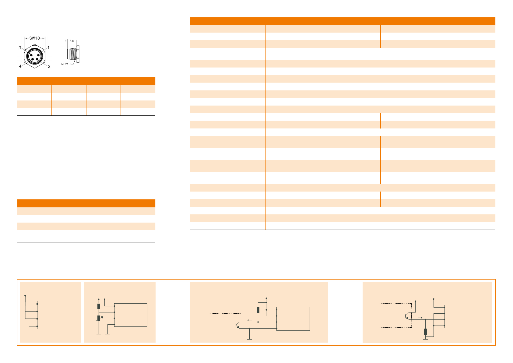
Connector M8x1 socket, 4 pin, male (for pinning details refer to chart “Electrical Connection”)
Accessories For cable, mounts and LED controller please check www.mbj-imaging.com
1) Values are approximate with a +/- 7% tolerance.
2) Lower voltage value refers to steady light, higher voltage value refers to flash light, please see max. allowed current in the rows below.
3) Power for Blue / Yellow is comparable to White, Power for Green is approx. 1,2 times higher.
4) Triggered flash light with max. 20ms and up to 100 % more light intensity, calculated for White.
Electrical Connection
The lighting is equipped with an 4 pin M8x1 connector.
Pin Color 1) Standard (-s) Direct (-x) 2)
1 brown 24 VDC LED (+)
2 white Dim LED (+)
3 blue Trigger LED (-)
4 black Ground LED (-)
1) wire color of MBJ lighting cable
2) connection to 24VDC without external LED controller may destroy the unit
Additional Information:
Pin3 (Trigger) is an ‘active high’ input signal with 5…24V=ON and 0...1 V=OFF,
it is a high resistance current sink with 0.2mA for 5V and 5 mA for 24 V
Pin2 (DIM) is used as brightness control and operation mode switch, it is a
high resistance current sink with 0.2mA for 5V and 1 mA for 24 V.
For the connection it is recommended to use the MBJ lighting cable with a
maximum length of 10 m.
Integrated Controller (-s)
Supported operation modes with the integrated LED controller
Pin 2 (Dim) Operation mode
24 V steady light 1)
1...10 V steady light with brightness control 2)
24 V triggered light
GND triggered flash light with max. 20ms and
up-to 100 % more light intensity 3)
1) Pin 3 (Trigger) needs permanent 24V to activate steady light mode
2) PWM with 3.8 kHz clock is used, recommended minimal camera exposure is 5ms
3) Latency between trigger and LED light ON is about max. 30 µs, the maximum recom-
mended clock speed is 1 kHz, the maximum recommended duty cycle is 25% and the
minimum recommended flash time is 100µs
Triggered light with NPN sinking output
(inverted strobe signal, open collector)
Flashed light with PNP sourcingSteady light Steady light with brightness control
Application Samples for (-s) controller
1 Power
2 Dim
3 Trigger
4 GND
24 VDC
MBJ
LED light
MBJ
LED light
1 Power
2 Dim
3 Trigger
4 GND
24 VDC
24 VDC
3k9
10k
24 VDC
2k2
11 mA
from Camera/ PLC etc MBJ
LED light
1 Power
2 Dim
3 Trigger
4 GND
2k2
MBJ
LED light
1 Power
2 Dim
3 Trigger
4 GND
24 VDC 24 VDC
15 mA
from Camera/ PLC etc

This manual suits for next models

4

Other mbj Lighting Equipment manuals

mbj High Power Series Instruction manual

mbj

mbj High Power Series Instruction manual

mbj Coaxial Light Series User manual

mbj

mbj Coaxial Light Series User manual

mbj DTL-ic-1020 User manual

mbj

mbj DTL-ic-1020 User manual

mbj SRL-12 User manual

mbj

mbj SRL-12 User manual

mbj SBL-0140 Series User manual

mbj

mbj SBL-0140 Series User manual

mbj Dome Light Series User manual

mbj

mbj Dome Light Series User manual

mbj HDF-05 User manual

mbj

mbj HDF-05 User manual

mbj SDL-05 User manual

mbj

mbj SDL-05 User manual

Popular Lighting Equipment manuals by other brands

Tronix 580-032 quick start guide

Tronix

Tronix 580-032 quick start guide

SICK deTec4 Core operating instructions

SICK

SICK deTec4 Core operating instructions

Philips Hue Runner user manual

Philips

Philips Hue Runner user manual

Kino Flo Diva-Lite 401 Operation manual

Kino Flo

Kino Flo Diva-Lite 401 Operation manual

NANLITE PavoTube II 15X user manual

NANLITE

NANLITE PavoTube II 15X user manual

Avlite AV-426-L861 Installation & service manual

Avlite

Avlite AV-426-L861 Installation & service manual

EuroLite OMNILUX PAR-38 230V E-27 70 instructions

EuroLite

EuroLite OMNILUX PAR-38 230V E-27 70 instructions

Tronix 600-022 manual

Tronix

Tronix 600-022 manual

MELINERA 279621 Operation and safety notes

MELINERA

MELINERA 279621 Operation and safety notes

IN HOUSE LED SICROBCF/EVO user manual

IN HOUSE LED

IN HOUSE LED SICROBCF/EVO user manual

PLG JOY 3 user manual

PLG

PLG JOY 3 user manual

numlighting Dune Assembly instructions

numlighting

numlighting Dune Assembly instructions

Storz TECHNO LED nova 100 instruction manual

Storz

Storz TECHNO LED nova 100 instruction manual

Robin Robin Cyclone user manual

Robin

Robin Robin Cyclone user manual

Velleman HQ-Power HQPE10006 user manual

Velleman

Velleman HQ-Power HQPE10006 user manual

LumenTruss 1450-OPTILUX Series Installation

LumenTruss

LumenTruss 1450-OPTILUX Series Installation

Finelite E3 LED Engine Replacement Instruction

Finelite

Finelite E3 LED Engine Replacement Instruction

Retlux RTL 202 operating manual

Retlux

Retlux RTL 202 operating manual

manuals.online logo
manuals.online logoBrands
  • About & Mission
  • Contact us
  • Privacy Policy
  • Terms and Conditions

Copyright 2025 Manuals.Online. All Rights Reserved.