manuals.online logo
Brands
  1. Home
  2. •
  3. Brands
  4. •
  5. mbj
  6. •
  7. Lighting Equipment
  8. •
  9. mbj DTL-ic-1020 User manual

mbj DTL-ic-1020 User manual

DTL-ic-1020 Diffuse Flat Dome Light
with flash controller and camera I/F
Note: Camera, cable and mount is not part of the product.
MBJ Imaging GmbH
Neuer Höltigbaum 15
DE 22143 Hamburg
support@mbj-imaging.com
www.mbj-imaging.com
Tel.: +49 40 226 1623 30
DTL-ic-1020 Series
Release: 1.04
21.02.2017
Bedienungsanleitung der diffusen DTL-ic-1020 Flat
Dome Beleuchtungen mit Blitzcontroller
Operating Manual of the DTL-ic-1020 diffuse flat dome
lighting with flash controller
1. Warn- und Anwendungshinweise
Bitte vor Verwendung des Gerätes die Warn- und
Anwendungshinweise sorgfältig durchlesen.
Allgemein - Das Gerät ist für nur die Verwendung in
Innenräumen ausgelegt.
Gesundheit - Ein direkter Blick in die Beleuchtung ist
grundsätzlich zu vermeiden. Bei Installations- und
Wartungsarbeiten ist die Beleuchtung vorher auszuschalten.
Das Gerät darf nicht verwendet werden, wenn ein Ausfall zu
einem Personenschaden führen kann.
Hitze - Bei unzureichender Wärmeableitung oder dem
Betreiben des Blitzmodus (über die CTR-Serie) als
Dauerlicht können Temperaturen größer 60°C auftreten. Es
ist auf ausreichendem Abstand zu leicht entflammbaren
Materialien zu achten.
Elektrischer Anschluss - Das Gehäuse ist von der Masse
der Spannungsversorgung elektrisch isoliert. Ein
Überschreiten der zulässigen Eingangsspannung Uin oder
das unzulässige Betreiben der Beleuchtung im Dauerlicht
kann zur Zerstörung des Gerätes oder zu einer erheblichen
Verkürzung der Lebensdauer des Gerätes führen.
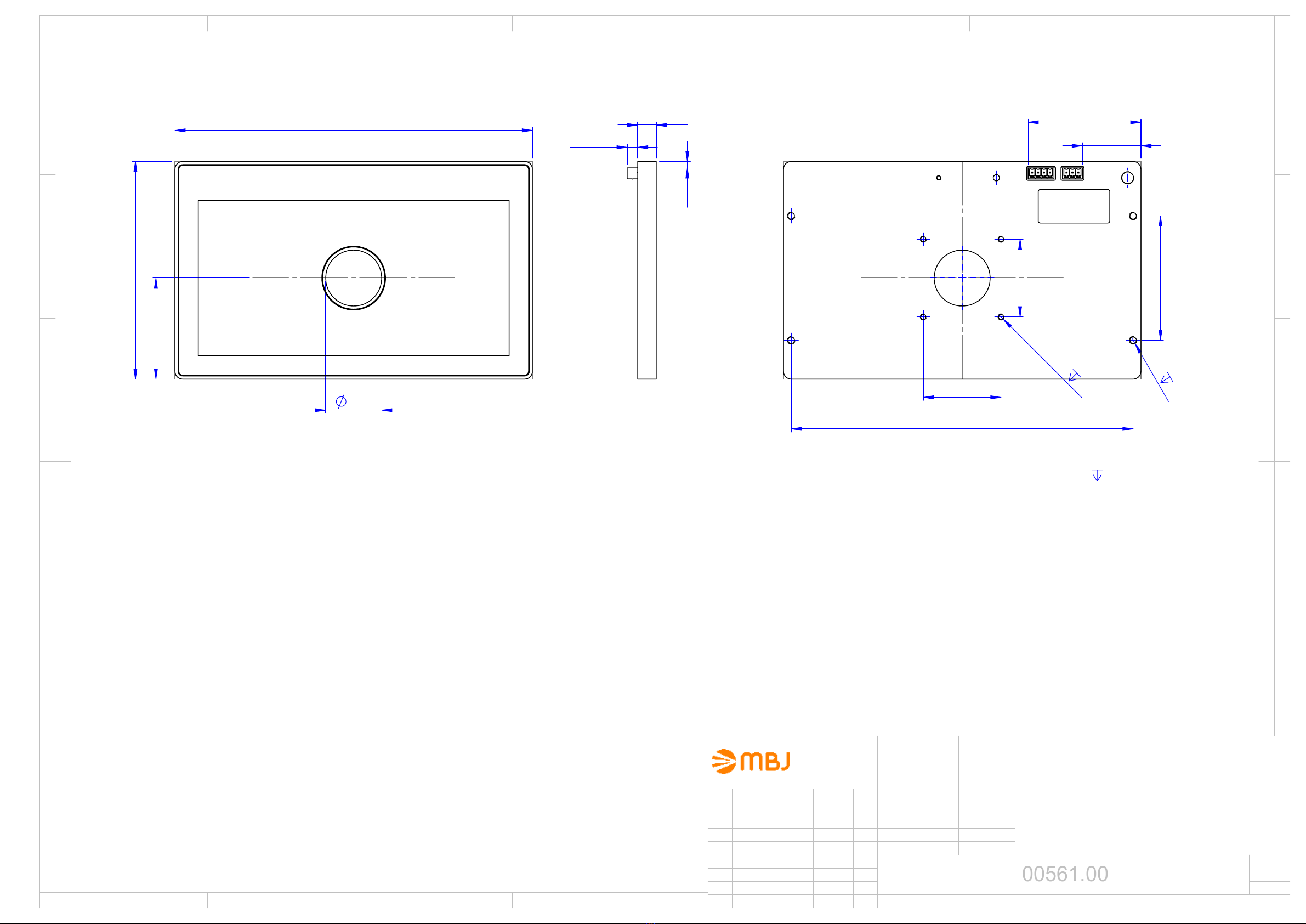
Mechanischer Einbau - Für die Befestigung der
Beleuchtungseinheit sind vier Montagebohrungen mit
Gewinde vorgesehen. Bitte die max. Einschraubtiefe nicht
überschreiten. Es kann zur Zerstörung des Gerätes führen.
Es ist auf ausreichende Wärmeableitung zu achten.
Benutzungshinweise – Bitte vermeiden Sie in Betrieb eine
mechanische Beanspruchung der Leuchtfläche. Dies kann
zu Kratzern und einem inhomogenen Lichtaustritt führen.
Reinigung – Die Leuchtfläche darf nur mit einem
handelsüblichen Glasreiniger und einem weichen Putzlappen
gereinigt werden.
1. Cautions and instructions for use
Please read the warning and application instructions carefully
before using the backlight.
General - The device is designed for indoor use only.
Health – Strictly avoid looking directly into the light source.
The lighting must be switched off before the installation
and/or maintenance. The device must not be used when a
failure may cause a personal injury.
Heat - In case of insufficient heat dissipation or supplying
to the device the max. flash voltage (Ub) is a continuous
operating mode (via the CTR series or directly) the surface
temperature may exceed 60 °C. Keep off flammable
materials at any time.
Electricity - The housing is electrically isolated from the
ground of the power supply. Exceeding the permissible input
voltage Uin or using the unit for continuous light application
can lead to the destruction of the device or to a significant
shortening of the lifetime of the LEDs of the device.
Mechanical integration - 4 screw-in tape holes can be used
to fix the lighting to specified position. It is essential to ensure
adequate heat transfer at the holding position. Please do not
exceed the maximum screw-in depth. I could destroy the
unit.
Usage – Please prevent during operation mechanical
stress to the light surface. This could lead to scratches and
inhomogenious light emission.
Cleaning - The light emission surface has to be cleaned
with a standard glass cleaner and a soft cleaning cloth only.
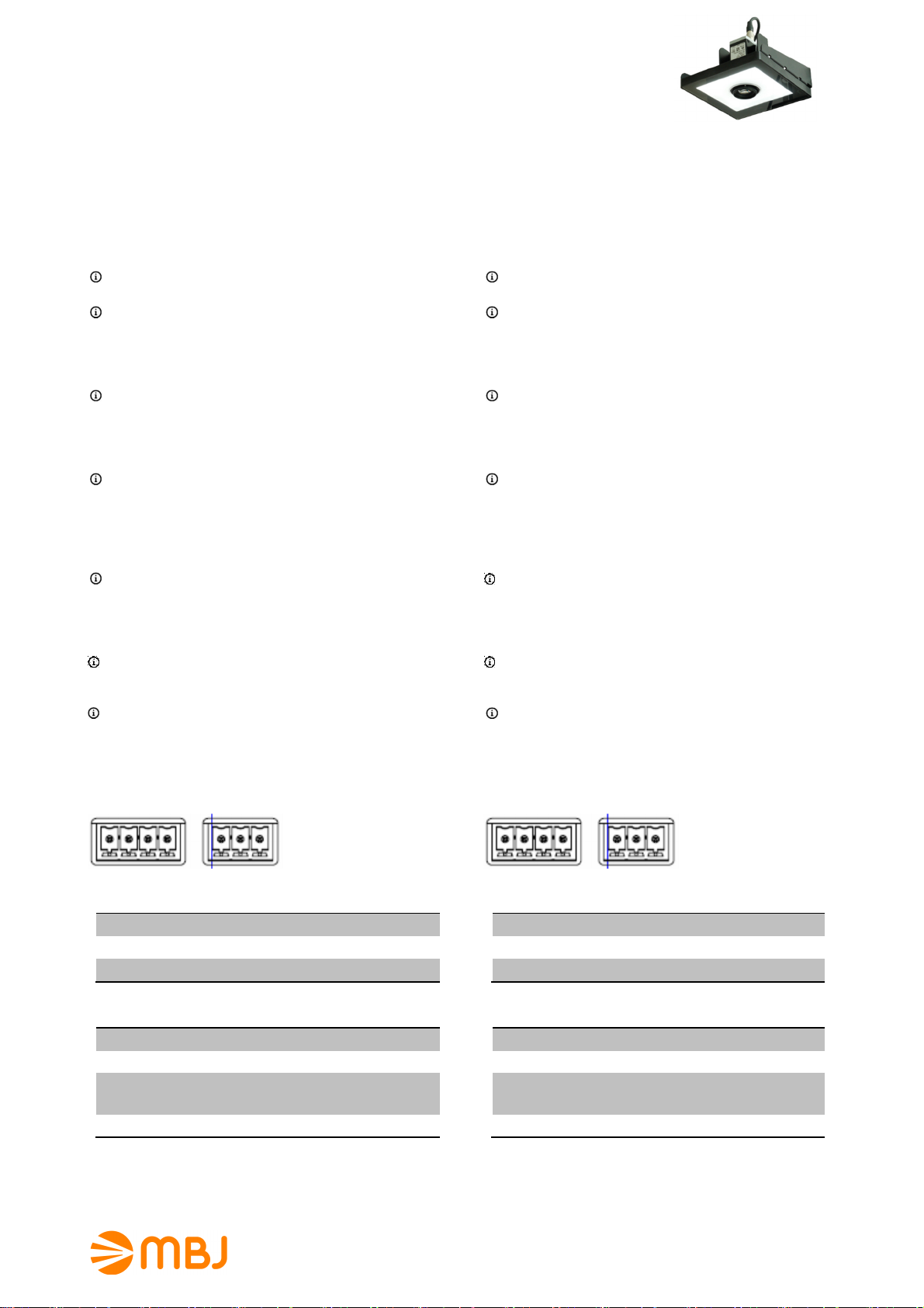
2. Elektrische Anschlüsse
Die Beleuchtung wird mit zwei Steckkontakten und
zugehörigen Steckern geliefert.
Pin4 Pin3 Pin2 Pin1 Pin3 Pin2 Pin1
Pin Interface nach Extern
1 Masse
2 Uin = 24V DC
3 I/O-In Signal (zur Kamera)
Pin Interface zur Kamera
1 Masse
2 Uout = 12V DC (Kamera Power)
3 I/O-Out Signal zur Blitzsteuerung
1) 2)
(Offen=Aus, Masse=An)
4 I/O-In Signal (von Extern)
1) Bitte die Verwendung des Exposure Active Signals der Kameraanleitung entnehmen.
2) Unterstützung von ‚open collector‘ I/O-Ausgängen, PullUp-R ist bereits integriert.
2. Electrical connection
The lighting is supplied with two plug-contacts and two plug
adapter as counter parts.
Pin4 Pin3 Pin2 Pin1 Pin3 Pin2 Pin1
Pin External interface
1 Ground
2 Uin = 24V DC
3 I/O-In signal (camera loop)
Pin Camera interface
1 Ground
2 Uout = 12V DC (camera power)
3 I/O-Out signal (flash control)
1) 2)
(Open=Off, GND=On)
4 I/O-In signal (camera loop)
1) Please check camera manual how to activate the exposure active signal,
2) Support for ‘open collector’ I/O-outputs, pull-up resistor already integrated.
DTL-ic-1020 Diffuse Flat Dome Light
with flash controller and camera I/F
Note: Camera, cable and mount is not part of the product.
MBJ Imaging GmbH
Neuer Höltigbaum 15
DE 22143 Hamburg
support@mbj-imaging.com
www.mbj-imaging.com
Tel.: +49 40 226 1623 30
DTL-ic-1020 Series
Release: 1.04
21.02.2017
3.
Betriebsmodus
Die Beleuchtung ist ausschließlich für den Blitzbetrieb aus-
gelegt. Die Blitzdauer wird über das I/O-Out-Signal der
Kamera bestimmt. Bei Bedarf kann die Grundhelligkeit über
einen internen Dimmer nachgeregelt werden.
4. Modellübersicht / LED-Farbe
LED Modell Wellenlänge
Weiß DTL-ic-1020-WT Spitze bei 460nm & 560nm
Rot DTL-ic-1020-RD Spitze bei 625nm
5. Strombedarf
Mode Weiß Rot
50%
1)
900mA 900mA
75%
2)
1800mA 1500mA
100%
3)
max 3.1A max 2.7A
1) Blitzbetrieb mit <1000ms Blitzzeit
2) Fabrikeinstellung, Blitzbetrieb mit < 30% Auslastungsgrad <100ms Blitzzeit
3) Blitzbetrieb mit < 10% Auslastungsgrad <1ms Blitzzeit
3.
Operating mode
The illumination is made for flash light usage only. The flash
duration is controlled by the I/O-out signal of the camera. If
necessary the brightness can be controlled by an internal
dimmer.
4. Model Range / LED Color
LED Model wave length
White DTL-ic-1020-WT peak near 460nm & 560nm
Red DTL-ic-1020-RD peak near 625nm
5. Operating current
mode White Red
50%
1)
900mA 900mA
75%
2)
1800mA 1500mA
100%
3)
max 3.1A max 2.7A
1) pulse mode with <1000ms flash time
2) Factory default, pulse mode with < 30% duty cycle and <100ms flash time
3) Pulse mode with < 10% duty cycle and <1ms flash time
6. Allgemeine Spezifikation
Leuchtfläche (axb) 100mm x 200mm
Lichtabstrahlung Auflicht mit 36mm Loch und
diffuser Abstrahlung
Empfohlener
Objektabstand
100mm bis 200mm,
abhängig vom Abbildungs-
maßstab, der Objektgröße und
der Beleuchtungsart
Betriebsspannung (Uin) 24V DC +/- 10%
Betriebsarten Kameragesteuerter Blitzbetrieb
Unterstützte Kameras Basler ace (GigE & USB3.0)
und weitere
Min. Blitzverzögerung Ca. 1 µs
Min. Blitzzeit Ca. 5 µs
Max. Pulsleistung WT: 22W (50%) / 84W (100%)
RD: 22W (50%) / 65W (100%)
Kameraausgang 12V DC, max. 400mA
Abmessungen 230mm x 140mm x 12mm
Gewicht 750g
Anschluss 3Pin Steckkontakt, RM3,81
4Pin Steckkontakt, RM3,81
Umgebungs-
temperatur
10°C bis 30°C
Schutzart IP54
Schutzklasse DIN EN 60825-1 Klasse 1
Luftfeuchtigkeit 30% bis 70%
Zubehör Siehe www.mbj-imaging.com
Webseite für diverse Kabel,
Halter und LED-Controller
6. General Specification
Luminous area (axb)
100mm x 200mm
Light emission
Diffuse incident light from
above with 36mm hole
Recommended
object distance
100mm to 200mm,
depending on reproduction
scale, the size of the object
and the type of illumination.
Operating voltage (Uin) 24V DC +/- 10%
Operating mode Camera controlled flash light
Supported cameras
Basler ace/USB3.0
and more
Min. flash delay Approx. 1 µs
Min. flash duration Approx. 5 µs
Max. pulse power
WT: 22W (50%) / 84W (100%)
RD: 22W (50%) / 65W (100%)
Camera Power 12V DC, max. 400mA
Dimensions 230mm x 140mm x 12mm
Weight 750g
Connector 3Pin male contact, RM3.81
4Pin male contact, RM3.81
Operating
temperature
10°C to 30°C
Degree of protection IP54
Protection class DIN EN 60825-1 class 1
Humidity 30% to 70%
Accessories For cable, mounts and LED
controller please check
www.mbj-imaging.com
DTL-ic-1020 Diffuse Flat Dome Light
with flash controller and camera I/F
Note: Camera, cable and mount is not part of the product.
MBJ Imaging GmbH
Neuer Höltigbaum 15
DE 22143 Hamburg
support@mbj-imaging.com
www.mbj-imaging.com
Tel.: +49 40 226 1623 30
DTL-ic-1020 Series
Release: 1.04
21.02.2017
7. Helligkeit für weiße LEDs
Die Beleuchtungsstärke wurde beim jeweiligen Abstand im
Zentrum der beleuchteten Objektfläche als Näherungswerte
erfaßt.
Objekt-
Abstand
Blitzlicht
50%-Mode
Blitzlicht
100%-Mode
10 mm 30 klux 60 klux
50 mm 15 klux 30 klux
100 mm 8.5 klux 18 klux
150 mm 4.5 klux 9 klux
200 mm --- ---
Angaben sind Näherungswerte mit +/-7% Toleranz
8. Mechanische Abmessungen
Siehe Zeichnung auf der folgenden Seite.
7. Illuminance for white LEDs
The illuminance of the light is measure at the center point of
the object surface at the given distance and it is an
approximate value.
Object
distance
Flash light
50% mode
Flash light
(100%) mode
10 mm 30 klux 60 klux
50 mm 15 klux 30 klux
100 mm 8,5 klux 18 klux
150 mm 4,5 klux 9 klux
200 mm --- ---
Values are approximate with +/-7% tolerance
8. Mechanical dimensions
Please refer to the drawing on the next page.
4Pin contact (camera IF) 3Pin contact (power IF) DTL-ic-1020 rear side view
IO-in trigger 12V GND IO-in 24Vin GND
Pin4 Pin3 Pin2 Pin1 Pin3 Pin2 Pin1
65
140
230
36
max. screw-in depth
light field 100x200
12
6,70
4,2
220
50
M5
9
80
50
M4
3
37,7
72,6
C
6
7
5
8
B
A
D
E
F
Allgemein-
toleranzen
Datum
Name
Bearb.
11.11.2015
F.Lorenz
Gepr.
Maßstab: 1:2
Gewicht:
TLi-1020
00561.00
Blatt
DIN A3
Verzeichnis: Z:\53 Zeichnungen\01 Einzelteile, Baugruppen\00561.00 TLi-1020 Baugruppe.SLDDRW
Name
Datum
Änderung
Zust.
1/1
Schutzvermerk nach DIN 34 beachten
11.11.2015
F.Lorenz
DIN ISO 2768-m
1
2
3
4
1
2
3
4
A
B
C
D
E
MBJ Imaging GmbH
Neuer Höltigbaum 15
D-22143 Hamburg

Other mbj Lighting Equipment manuals

mbj HDF-05 User manual

mbj

mbj HDF-05 User manual

mbj SRL-12 User manual

mbj

mbj SRL-12 User manual

mbj SBL-0140 Series User manual

mbj

mbj SBL-0140 Series User manual

mbj Dome Light Series User manual

mbj

mbj Dome Light Series User manual

mbj Domelight Series User manual

mbj

mbj Domelight Series User manual

mbj Coaxial Light Series User manual

mbj

mbj Coaxial Light Series User manual

mbj High Power Series Instruction manual

mbj

mbj High Power Series Instruction manual

mbj SDL-05 User manual

mbj

mbj SDL-05 User manual

Popular Lighting Equipment manuals by other brands

Optic arts FLEX ACV2 installation guide

Optic arts

Optic arts FLEX ACV2 installation guide

PLG DAFNE ADJ user manual

PLG

PLG DAFNE ADJ user manual

SLV 113150/51 operating manual

SLV

SLV 113150/51 operating manual

EGAmaster MASTEREX 77780 instruction manual

EGAmaster

EGAmaster MASTEREX 77780 instruction manual

Qlight QT50L-USB-BZ manual

Qlight

Qlight QT50L-USB-BZ manual

superbrightleds STN-3-UC user manual

superbrightleds

superbrightleds STN-3-UC user manual

DekoLight 733055 Product notes

DekoLight

DekoLight 733055 Product notes

GOAL ZERO CRUSHLIGHT CHROMA user guide

GOAL ZERO

GOAL ZERO CRUSHLIGHT CHROMA user guide

HQ Power VDL10MB2 user manual

HQ Power

HQ Power VDL10MB2 user manual

Litepanels Gemini 1x1 Soft manual

Litepanels

Litepanels Gemini 1x1 Soft manual

superbrightleds WPGL Series user manual

superbrightleds

superbrightleds WPGL Series user manual

X-Cite FLOOD XCFC100NW Installation & operating instructions

X-Cite

X-Cite FLOOD XCFC100NW Installation & operating instructions

WalimeXPro 15537 instruction manual

WalimeXPro

WalimeXPro 15537 instruction manual

Show Tec Medium Studiobeam Tour Q4 4-in-1 LED V2 manual

Show Tec

Show Tec Medium Studiobeam Tour Q4 4-in-1 LED V2 manual

HQ Power VDPLPS3612 Series user manual

HQ Power

HQ Power VDPLPS3612 Series user manual

superbrightleds LPL-RGB9WR manual

superbrightleds

superbrightleds LPL-RGB9WR manual

dj power DSK 1500 V user manual

dj power

dj power DSK 1500 V user manual

Delta Light FEMTOLINE 35 F HE PROFILE Installation instruction

Delta Light

Delta Light FEMTOLINE 35 F HE PROFILE Installation instruction

manuals.online logo
manuals.online logoBrands
  • About & Mission
  • Contact us
  • Privacy Policy
  • Terms and Conditions

Copyright 2025 Manuals.Online. All Rights Reserved.