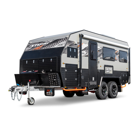
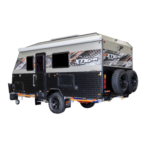
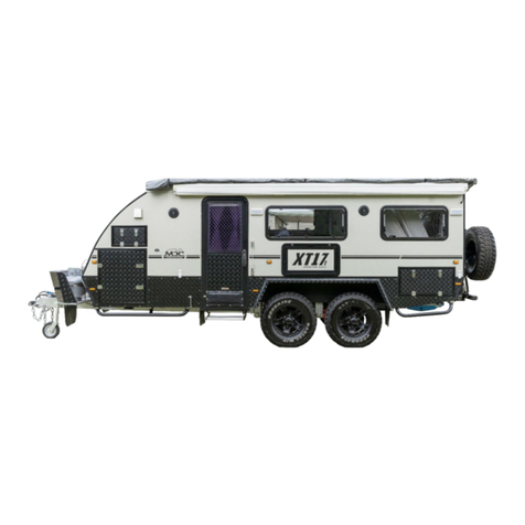
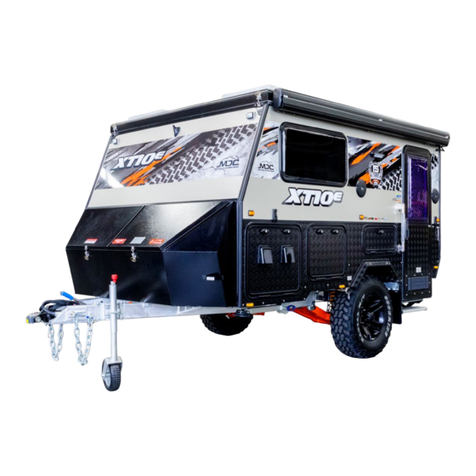
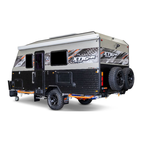
MDC XT15-PT Assembly instructions

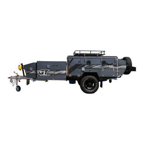
XT15-PT
User Manual and Guide
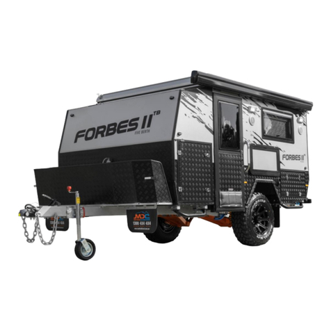
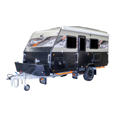
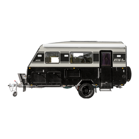
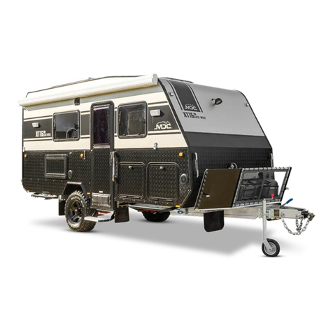
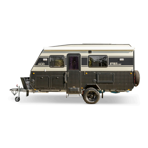
2017-2018 Model Shown
©Copyright Market Direct Campers & Caravans 2018
Read owner’s manual before using the equipment. Third party component manuals should be read in conjunction
with this manual. Maintenance guidelines must be met or exceeded, failing to meet these guidelines may result in
serious injury or death and property damage.

1
1300 4X4 4X4

2
1300 4X4 4X4
Table of Contents
INTRODUCTION ....................................................... 3
Store Locations ........................................................ 4
Contact Details......................................................... 4
ABOUT YOUR HYBRID OFFROAD CARAVAN ......... 5
Specifications........................................................... 5
Bearings and Seals ................................................... 5
Fridge Fitting Chart .................................................. 6
Hitch......................................................................... 6
How to Hitch your coupling ................................. 7
Coupling ............................................................... 9
Uncoupling......................................................... 11
Setting up your Caravan ............................................ 12
Loading Your Caravan............................................ 12
Choosing a Spot to Set Up ..................................... 12
Levelling Your Caravan .......................................... 13
Site Power.............................................................. 13
Electric Awning ...................................................... 13
Leg Rests ................................................................ 14
Kitchen................................................................... 14
Preparing for Bad Weather.................................... 15
Packing Down Your Caravan.................................. 15
Storage & Care .......................................................... 15
Long Term Storage................................................. 15
Interior................................................................... 15
Exterior .................................................................. 15
Torque Settings...................................................... 16
Wheel Nuts ........................................................ 16
Hitch................................................................... 16
Trailing Arm Pivot Bolts ..................................... 16
Brakes and Handbrake........................................... 17
Features ............................................................. 17
Operation........................................................... 17
Trailer Plug Wiring ............................................. 17
Breakaway Switch.............................................. 17
Hand Brake ........................................................ 18
Adjuster ............................................................. 19
Correct Use of Your Electric Brakes....................20
Important Safety Notice.....................................20
Brake Adjustment...............................................20
Brake Cleaning and Inspection...........................20
Magnets..............................................................21
Shoes and Linings ...............................................21
Corrosion Prevention .............................................21
Wheels and Tyres ......................................................22
Highway..............................................................22
Off Road .............................................................22
Jacking Your Caravan..........................................22
Electrical Systems ......................................................22
Chargers & Inverters ..............................................22
Battery Care ...........................................................23
12 Volt Wiring Diagram..........................................24
Control Panel..........................................................26
Gas & Water Systems ................................................26
Hot Water System ..................................................26
Water Pumps..........................................................26
Connecting the Gas ................................................27
Protecting from Mould ................................................28
Pre-Trip Checklist .......................................................28
Useful Accessories .....................................................29
Levelling Blocks ......................................................29
Wheel Chocks.........................................................30
Covers.....................................................................30
Stone Protection ....................................................30
Trouble Shooting ........................................................31
Electrical .................................................................31
Water......................................................................32
Gas..........................................................................32
Brakes.....................................................................33
Handy Tips .................................................................34
Driving Off Road .....................................................34
Trip Planning ..........................................................35
Warranty Statement ...................................................36
Maintenance ...............................................................37
Supplier Contact Details.............................................46
3
1300 4X4 4X4
INTRODUCTION
WARNING– Before using this product you should read this manual and those
manuals supplied by component manufacturers applicable to this product.
This manual is supplied as a reference to required maintenance of the product. Failure to
use and maintain the product in accordance with what is outlined in this manual may affect
your warranty.
Incorrect and/or insufficient maintenance may cause product failure resulting in property loss, damage
or injury or death. Maintenance intervals are critical for normal use, extreme use may require shorter or
additional maintenance intervals.
Manual content does not imply. express or other any warranty, the owner should read the limited
warranty terms included in this booklet.
Before using this product, you should be certain your tow vehicle is suitably rated and equipped to tow the
product safely and legally. The trailer and vehicle pairing must we within the safe “Maximum Towing
Capacity”, “Ball Weight Capacity” and “Gross Combination Mass” as stated by the vehicle manufacturer.
This caravan is fitted with electric brakes and a “Breakaway System”. Requirements for breakaway
systems can vary from state to state. It is mandatory to supply a maintenance charge to the breakaway
battery source while driving. You MUST ensure this capability is fitted to your vehicle. The maintenance
charge is supplied to the caravan via the Anderson plug on the drawbar.

4
1300 4X4 4X4
Store Locations
QUEENSLAND
Brisbane
3/711 Beaudesert Rd
Rocklea QLD 4107
Cairns
395 Sheridan St
Cairns North QLD 4870
Townsville
437 Bayswater Rd
Garbutt QLD 4814
Caboolture
4 Boeing Place
Caboolture QLD 4510
NEW SOUTH WALES
Sydney
178-180 Hume Hwy
Lansvale NSW 2166
Newcastle
Unit 1, 2364 Pacific Hwy
Heatherbrae NSW 2324
VICTORIA
Melbourne
126 Canterbury Rd
Kilsyth South VIC 3137
North Geelong
129 Douro Street
Nth Geelong VIC 3215
WESTERN AUSTRALIA
Wangara
63 Innovation Circuit
Wangara WA 6065
Kenwick
1752 Albany Way
Kenwick WA 6107
SOUTH AUSTRALIA
Adelaide
1246 South Rd
Clovelly Park SA 5042
Contact Details
NATIONAL TOLL FREE
WARRANTY HOTLINE
SPARE PARTS
1300 4X4 4X4
1300 494 494
1300 MDC CARE
1300 632 2273
1300 MDC PARTS
1300 632 72787

5
1300 4X4 4X4
ABOUT YOUR HYBRID OFFROAD CARAVAN
Specifications
Specifications apply to:
2017-18 Model Only
Berth
2
Trailer Length
6510mm (hitch to tailgate)
ATM
2800kg
Chassis Construction
150mm x 50mm x 4mm (galvanised)
Body Construction
Aluminium Composite Panel, Fully Welded Frame +
Chassis
Suspension
Fully Independent Trailing Arm Suspension with 4 Shock
Absorbers
Wheels & Tyres
2 x 16” Rims + 1 spare, Goodride Mud Terrain 265/75
R16
Hitch
3500kg Vehicle Components
Brakes
12” Electric Off Road with Hand Brake
Stone Guard
Included with Stone Tamer Mudflaps
Gas Cylinders
2 x 9kg Gas Cylinder Holders incl 2 Gas Cylinders
Jerry Can Holder
2 x 20L Jerry Can Holders
Cooktop
Thetford Triplex 3 Burner with Oven/grill
Kitchen Construct
External 304 Grade Stainless Steel (optional sizzler
BBQ)
Refrigerator
Dometic Coolmatic 65 litre
Water Tank
2 x 80L Fresh Water 1 x 80L Grey Water
Water Delivery
12v Electric Pump x 1
Hot Water System
Truma “Boiler” 14 Litre Gas
Shower (Ensuite)
Hot/Cold Internal Ensuite with External Van Side
Mounted Shower Tent
Battery
2 x 100AH Deep Cycle AGM Batteries
Awning
Electric
AC Charger (240v)
Projecta IDC3500-12v 35A 7 Stage
DC Charger (12v)
Projecta IDC25-9-32v 25A 3 stage
Inverter
Projecta IM1000-12v 1000w Continuous/2000w Peak
Bearings and Seals
Bearings are a consumable item should be removed, inspected and repacked with grease every 5,000km and
replaced every 10,000km as best practice. See maintenance schedule for guidance.
Bearing Number: Inner Bearing 25590
Cone: 25520
Outer Bearing 25590
Cone: 25520
Seal: 55 x 85 x 12

6
1300 4X4 4X4
Fridge Fitting Chart
Engel Evakool Bushman Ironman LARB
MT35FP
ED65
35L
30L
35
Glacier G61
40L
35L
RF40
RF47
Hitch
Current 2018 onward model XT15HR is fitted with a Vehicle Components ADR approved DO35 hitch. Previous models
may be fitted with a McHitch coupling. For information on McHitch couplings and spare parts contact the manufacturer
www.mchitch.com.cu
Phone: (02) 63 512 533
Fax: (02) 63 512 633
Mobile: 0402 863 867
Email: joe@mchitch.com.au

7
1300 4X4 4X4
How to Hitch your coupling
Here is a short guide on how to safely use your coupling to couple and uncouple the
trailer from the towing vehicle.
Make sure the handbrake is applied prior to coupling and uncoupling.

8
1300 4X4 4X4
Make sure the dust cap is securely connected to the bump cover. This is done by locating the rear lip on the
dust cap onto the groove of the bump cover and then pushing it in a downward motion until the dust cover is
secure (there should be a slight click when it has been assembled correctly) Test if the dust cover is connected
to the bump cover by applying a slight upward force to the dust cover, it shouldn’t separate.
This procedure should be applied if you are uncoupling or coupling up.

9
1300 4X4 4X4
Coupling
STEP 1
Push down the button (1) and push the locking mechanism back (2). When the locking mechanism (2) is all
the way back, release the button (1) locking the plate in place
STEP 2
Offer up the tow pin to the coupling making sure the tow pin cover is removed and there is no visible debris on
it. Locking plate should be in unlocked position as shown. Lower the coupling onto the tow pin.

10
1300 4X4 4X4
STEP 3
Make sure the tow pin is seated inside the universal and the tow pin top is sticking out of the locking
mechanism (see below). Press the button (1) to release the locking mechanism there will be an audible
locking noise at which point the mechanism will return to the initial position as shown in step 1. Verify the pin is
correctly through the mechanism and assemble the cap. If the cap will not fit check the locking mechanism is
in the correct locked orientation.
Detail view of pin through locking mechanism.

11
1300 4X4 4X4
Uncoupling
STEP 1
Push down the button 1 and push the locking mechanism back 2. When the locking mechanism is all the way
back release the button while holding the mechanism to ensure it does not spring back to the locked position.
STEP 2
Lift the coupling up off the tow pin.

12
1300 4X4 4X4
Seng up your Caravan
Loading Your Caravan
It is important to load your caravan correctly to distribute weight evenly and achieve a suitable ball weight load and
prevent loading in a manner that can cause a caravan to sway and/or roll excessively left and right. The optimum ball
weight on a caravan is between 9 and 11% of the total caravan weight.
WARNING: BALL LOADING (DOWNWARD LOAD ON TOW HITCH) MUST NOT EXCEED 350KG OR THE
MAXIMUM ALLOWABLE LOAD BY THE VEHICLE MANUFACTURER OR TOW BAR RATING, WHICH EVER IS
THE LOWEST. Exceeding these limits may result in an accident causing serious injury or death and/or
property damage.
•Always load evenly to both sides of the caravan
•Load heavy weight over or as close to over the axle as possible and as low as possible
•Overhead cupboards should only be used for lightweight items such as clothes, personal items, bedding etc.
•Heavy cooking equipment should be stored in lower cupboards.
•Tinned food, bottled goods for cooking etc should be stored in the pantry cupboard.
•Never load in a manner that causes the ball weight to exceed the limit of the tow vehicle.
•Ensure no items can move during travel. Secure all items to prevent damage to the caravan.
•Consider water tank levels and how they may affect the balance front and back and the percentage of ball
weight.
•Never store heavy items in overhead cupboards.
The diagram below illustrates best placements of items based on weight.
Choosing a Spot to Set Up
When choosing a spot to set up your caravan, start with a flat area with no overhanging trees. Birds and bats
occupying trees can defecate leaving droppings on your caravan that can damage paint and leaves and sap can also
stain the coating. Ensure you are not camping in an area prone to flooding or with bad drainage in the event of rain.
Even the slightest hollow in the ground can put you in a mini lake. In hot weather if possible, set your caravan up so
the sun’s arc goes from front to back or back to front with the annex/awning in the general direction the sun is arcing
across. Doing this will keep the bulk of the caravan in shade and the inside cooler as it will be shaded by the awning.

13
1300 4X4 4X4
Levelling Your Caravan
The stabiliser legs on your caravan are not designed for supporting the full weight of the trailer, they are there to
stabilise it once it is level. Using your stabilisers as a lifting mechanism will void your warranty as will extending them
with a “rattle gun” or “impact wrench”. Levelling front to back can be done by raising and lowering the jockey wheel
prior to adjusting the stabiliser legs. Getting the trailer level from left to right should be done with drive on stepped
ramps as illustrated below. Once levelled the legs can be lowered to keep the trailer stable. On soft ground you may
want to use timber sole boards under the stabiliser feet.
Site Power
The Projecta charger in your caravan is connected via the 15A exterior socket. To use site power you will require a
15A power lead connected to a 15A outlet. In the event a 15A outlet is unavailable you will need a conversion box that
will step up from 10A to 15A with a safety switch. Never leave power leads coiled when in use, lay the lead out back
and forward in a manner that won’t be a trip hazard or risk damage to the lead.
Electric Awning
When extending the awning always support to front as it extends. Do not allow the awning to carry the full extended
weight as this may damage the hinges. Support the end manually by hand or by using the extendable legs.

14
1300 4X4 4X4
Leg Rests
The extensions to the lounge area seating are NOT SEATS they are leg rests. Do not under any circumstances use
for seating.
Kitchen
To extend the kitchen from the caravan, press down the blue slide tabs and pull kitchen out. The kitchen will lock into
place when extended. To put kitchen away, again press down the blue tabs and push back into place.
To connect the water and gas, plug the hoses and gas bayonet as per the diagram below.

15
1300 4X4 4X4
Preparing for Bad Weather
During inclement weather the following should be done:
• Close all roof vents and hatches to prevent water entering.
• Protect the awning from high winds by retracting or securing with guy ropes and pegs.
• Ensure your caravan is not parked in ground that will become boggy and prevent exiting the camp area
• Close all external doors and hatches to prevent water ingress and wind damage
Packing Down Your Caravan
When packing down your caravan ensure the following:
•All gas and electric appliances are turned off
•Gas is turned off at the gas bottle
•All loose items are secured and unable to move and damage themselves or the caravan
•All cabinet doors are secured and locked along with all drawers closed
•Roof is lowered, and over centre latches are locked with safety pin engaged
•Site power lead is removed and stowed
•Doorstep is raised and secured
•All roof hatches lowered and secure
•All windows closed and locked
•Main door is closed and locked
•All dust covers in place and secure
Storage & Care
Long Term Storage
To maximise the life of your caravan you should consider additional protection from the elements. UV light and
moisture can have an adverse effect on materials when left unprotected outside. This section outlines some of the
things you can do as an owner to protect your investment.
Interior
Moisture in the smallest amounts can cause mould. High humidity and cooling temperatures can create condensation,
additionally condensation can form under mattresses due to temperature differences between warm bodies on top and
the bed base being cold from outside temperatures. As a precaution you can do the following:
•Check under mattress for moisture before packing up. If moisture is found allow to thoroughly dry before
closing your camper.
•Store 1 or 2 moisture absorbing packs/dehumidifier packs in the caravan to draw away any residual water
vapour.
•If packing up with damp or humid conditions, open and dry out the caravan at the first opportunity when
returning home.
Exterior
Ensure all seals on the caravan have proper compression at 30-50%, are free of dirt and have nothing protruding past
the seals. UV light and the elements can over time cause seals and fittings to perish and become brittle. The use of a
caravan cover will extend the life of components and keep your investment looking better for longer.

16
1300 4X4 4X4
Securing Your Caravan
When parked and unhitched you should always use suitable wheel chocks to ensure the trailer can’t move in the event
of a handbrake failure. For security a wheel clamp or and hitch lock are highly recommended.
Torque Settings
Wheel Nuts
Wheel nuts should be tightened to correct torque using a torque wrench. Never trust a “rattle gun” as these may over
or under tighten. A quality torque wrench will ensure nuts are tightened correctly. It’s important to remember to check
your wheel nuts at 50km, 500km and 1000km and periodically thereafter. The correct torque setting of 125Nm for
12mm studs, 140nm for 14mm studs with alloy wheels and 200nm for 14mm studs with steel rims. Refer to the plate
on your drawbar.
Hitch
The high tensile bolts securing your hitch should be tightened to 76Nm. These should be checked at 5000km intervals
or 2500km in harsh off-road conditions.
Trailing Arm Pivot Bolts
The pivot bolts are a high tensile steel. The service interval for these bolts is 5000km under normal use and 2500km

17
1300 4X4 4X4
for harsh off-road conditions. During travel they should be inspected daily to ensure they have not rotated or become
damaged. Correct torque is 190Nm
Brakes and Handbrake
Features
Your trailer is fitted with electric brakes that require a brake controller that can be operated from the driver’s seat.
1. Manual adjusted to provide the correct braking capability for varying road, off-road and load conditions.
2. They can be modulated to provide variable braking force, thus easing the brake load on the towing vehicle.
3. There is very little lag time between the moment the tow vehicle’s brakes are actuated and the moment the
trailer brakes are actuated.
4. They can provide some braking independent of the tow vehicle in the event of an emergency.
Operation
When electrical current is fed into the system by the controller, it activates the electromagnets in the brakes. These
electromagnets are energized and are attracted to the rotating surface of the drums which moves the actuating levers
in the direction that the drums are turning thus applying pressure from the brake linings to the drum surface
Trailer Plug Wiring
The following diagrams outline the correct wiring for 7 pin plug
Breakaway Switch
By law, all trailers with an ATM of 2000kg or greater must have a “Breakaway System” to halt the trailer in the event it
becomes detached from the tow vehicle whilst traveling. Your caravan is fitted with this system with the switch
mounted on the drawbar with a steel wire lanyard to connect to your tow vehicle. In the event that the caravan
becomes detached, the lanyard will pull the pin from the breakaway switch and the onboard batteries will activate the
brake system. The lanyard must be attached to a solid part of the vehicle. It is a mandatory requirement that power be

18
1300 4X4 4X4
supplied by the tow vehicle to the breakaway power source while towing. This is done via the 50amp Anderson Plug
on the drawbar. Consult a qualified auto electrician to ensure this is fitted to your tow vehicle.
In NSW there is an additional requirement that the breakaway power source be monitored from the driver position with
a minimum of a “visual alarm” for low battery voltage. Consult a qualified auto electrician to ensure this is fitted to your
vehicle.
Breakaway Switch Anderson Plug
CAUTION:
•DO NOT CONNECT THE BREAKAWAY LANYARD TO THE SAME POINT AS THE SAFETY CHAIN
SHACKLES.
•DO NOT USE THE BREAKAWAY AS AN ALTERNATIVE TO THE HANDBRAKE AND DO NOT REMOVE
THE PIN AS AN ALTERNATIVE SECURITY MEASURE. REMOVING THE PIN WILL RAPIDLY DISCHARGE
THE BATTERIES.
•IT IS A MANDATORY REQUIREMENT THAT THE BREAKAWAY BATTERY SOURCE BE CHARGED
DURING TOWING.
•NSW REQUIRES A BATTERY MONITOR VIEWABLE FROM THE DRIVERS POSITION WITH A MINIMUM
OF A VISUAL ALARM FOR LOW BATTERY VOLTAGE
Hand Brake
Parking brakes are mechanically operated by cable means. The cable attachment occurs outside of the brake backing
plate. Cable force applied to the parking lever creates a torque through the pivot pin and cam assembly. Torque
transferred to the parking cam results in a spreading force between the primary and secondary shoes. The shoes in
turn, move towards the drum until contact is made. Friction generated between the drum and lining contact surface
results in parking brake capability.
Use the cable adjuster to give enough tension to be able to set the handbrake lever on the last two notches of the
coupling or handbrake is 1/3 raised when unladen. This needs to be checked again when the trailer or caravan is
loaded. If the cable is too tight, the brakes will be applied as the axle moves backward under spring deflection.

19
1300 4X4 4X4
Adjuster
To adjust the handbrake cable tension release locknuts A, B and C in the diagram Handbrake Adjuster 1 below. To
tighten the handbrake cable, turn the adjuster wheel D in a clockwise direction. Once adjusted retighten lock nuts and
test. Always ensure that wheels turn freely when handbrake is off. Overtightened cables can cause brakes to drag and
damage the brake linings.
Table of contents
Other MDC Caravan manuals

MDC
MDC Forbes11TB Assembly instructions

MDC
MDC XT-17 User manual

MDC
MDC XT10E 2021 User manual

MDC
MDC XT16HR ISLAND 2022 User manual

MDC
MDC EXPLORER 2021 User manual

MDC
MDC XT12HR 2021 User manual

MDC
MDC CRUIZER HIGHSIDE 2021 User manual

MDC
MDC XT14E Assembly instructions

MDC
MDC XT11 Assembly instructions

MDC
MDC XT17-HRT 2018 Assembly instructions

MDC
MDC XT16-HR East West Assembly instructions

MDC
MDC XT17T 2022 User manual

MDC
MDC XT11E Assembly instructions

MDC
MDC XT17HRT 2022 User manual

MDC
MDC XT11 2020 Assembly instructions

MDC
MDC XT12 2021 User manual

MDC
MDC JACKSON 2021 User manual

MDC
MDC XT14E 2021 User manual

MDC
MDC FORBES 15+ 2021 User manual

MDC
MDC 15 YEAR ANNIVERSARY XT16HR ISLAND 2022 User manual