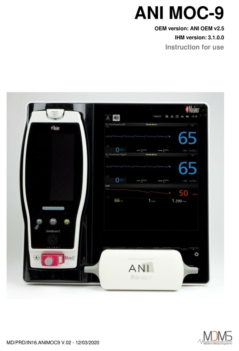
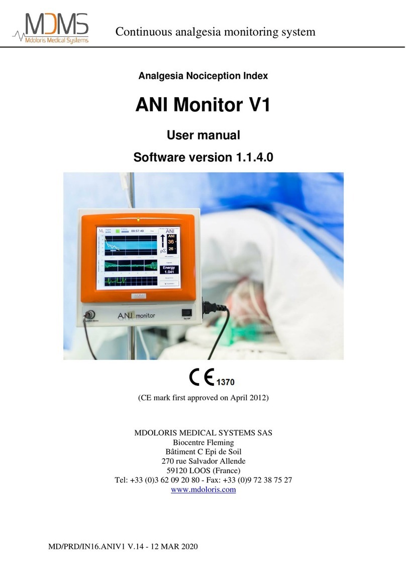
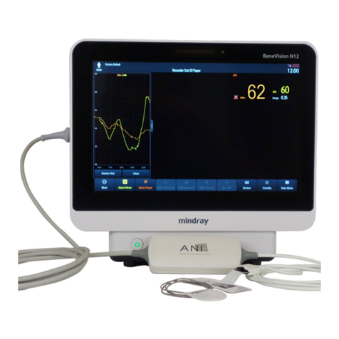
Mdoloris ANI MONITOR V2 User manual

ANI Monitor V2 - Continuous analgesia monitoring system
MD/PRD/IN16.ANIV2 v.07 –29 SEP 2021
User manual
ANITechnology
ANI MONITOR V2
Software version: 2.2.2.0
1370
(CE mark first approved: February 2017)
MDOLORIS MEDICAL SYSTEMS SAS
Biocentre Fleming
Bâtiment C Epi de Soil
270 rue Salvador Allende
59120 LOOS
FRANCE
Tel: 03 62 09 20 80 - Fax: 09 72 38 75 27
www.mdoloris.com

ANI Monitor V2 - Continuous analgesia monitoring system
MD/PRD/IN16.ANIV2 v.07 –29 SEP 2021
©Mdoloris Medical Systems. All rights reserved. Copying or other reproduction of this
document is prohibited without prior written consent of Mdoloris Medical Systems.
Mdoloris Medical Systems is registered trademark.
ANI is a protected trademark.
Important information about the intended use of ANI MONITOR V2:
The Mdoloris Medical Systems’ ANI MONITOR V2 is designed to be used for adult and
paediatric patients from the age of 2 years.
ANI MONITOR V2 is intended for use under the direct supervision of a licensed
healthcare practitioner or by personnel specifically trained for its use in a medical
environment and non-sterile.
ANI MONITOR V2 allows monitoring the tone of the parasympathetic nervous system
on conscious patient.
It may be used to monitor the effects of certain analgesic agents.
ANI MONITOR V2 is intended for use as an adjunct to clinical judgment.
Clinical judgment should always be used when interpreting the ANI index in
conjunction with other available clinical signs.
Reliance on ANI alone for interpreting analgesic management is not recommended. As
with any monitored parameter, artifacts and poor signal quality may lead to
inappropriate ANI values. Potential artifacts may be caused by muscle activity or
rigidity, patient motion, improper sensor placement or electrical interference.
Known contraindications where the ANI measurement cannot be interpreted:
•arrhythmia
•apnea (e.g. apnea induced by anesthesia)
•respiratory rate lower than 9 cycles/min
•electric noise during the measurement period (64 seconds)
•irregular spontaneous ventilation (patient speaking, laughing or coughing)
•pace maker (certain types)
•heart transplant
•drugs affecting the sinus node (atropine and other anticholinergic drugs, etc.)

ANI Monitor V2 - Continuous analgesia monitoring system
MD/PRD/IN16.ANIV2 v.07 –29 SEP 2021 P a g e 3 | 44
Contents
1Safety precautions......................................................................................................... 5
1.1 Warnings and safety instructions............................................................................ 5
1.2 Key to symbols......................................................................................................... 10
2ANI MONITOR V2.......................................................................................................... 11
3Installating the ANI MONITOR V2 ............................................................................ 11
3.1 Perfusion stand........................................................................................................ 11
3.2 Table.......................................................................................................................... 11
3.3 ANI-SENS-V1........................................................................................................... 12
3.4 ANI MONITOR V2 Connection.............................................................................. 13
4Beginning ANI monitoring V2................................................................................... 14
5Using the ANI MONITOR V2 and setting parameters......................................... 16
5.1 ECG Capture............................................................................................................ 16
5.2 Respiratory pattern.................................................................................................. 17
5.3 ANI index.................................................................................................................. 18
5.4 ANI navigation.......................................................................................................... 19
6ANI MONITOR V2 settings......................................................................................... 19
6.1 Language parameters............................................................................................. 19
6.2 Threshold.................................................................................................................. 20
6.3 Events ....................................................................................................................... 22
6.4 Expert mode and energy index............................................................................. 23
7Ending ANI monitoring............................................................................................... 26
7.1 Stopping the recording of a case.......................................................................... 26
7.2 Demo......................................................................................................................... 26
7.3 New patient............................................................................................................... 26
7.4 Maintenance............................................................................................................. 27
7.5 Deleting patient data............................................................................................... 27
7.6 Screen capture......................................................................................................... 27
7.7 Exporting data files.................................................................................................. 27
7.8 Updating events....................................................................................................... 31
7.9 Setting date and time.............................................................................................. 32
7.10 Updating monitor..................................................................................................... 33
7.11 Shutting down .......................................................................................................... 35
8Trouble shooting.......................................................................................................... 35
9Monitor disposal........................................................................................................... 36
10 Environment.................................................................................................................. 36

ANI Monitor V2 - Continuous analgesia monitoring system
MD/PRD/IN16.ANIV2 v.07 –29 SEP 2021 P a g e 4 | 44
10.1 Shipping and storage conditions........................................................................... 36
10.2Operating environment........................................................................................... 37
10.3 Power requirements and grounding..................................................................... 37
11 Cleaning and disinfection.......................................................................................... 37
11.1 Cleaning.................................................................................................................... 37
11.2 Maintenance............................................................................................................. 38
12 Specifications, warranty and software license contract................................... 39
12.1 Specifications........................................................................................................... 39
12.2 Accessories.............................................................................................................. 40
12.3 Warranty ................................................................................................................... 41
12.4 Software License Agreement................................................................................ 42

ANI Monitor V2 - Continuous analgesia monitoring system
MD/PRD/IN16.ANIV2 v.07 –29 SEP 2021 P a g e 5 | 44
1 Safety precautions
Caution: read this entire manual carefully before using the monitor in a clinical setting.
1.1 Warnings and safety instructions
GROUND LEAKAGE CURRENT MUST BE CHECKED BY A QUALIFIED BIOMEDICAL
ENGINEERING TECHNICIAN WHENEVER INSTRUMENT CASE IS OPENED.
PROTECTION AGAINST HEART DEFIBRILLATION SHOCK DEPENDS ON USING THE
APPROPRIATE CABLES.
EXPLOSION HAZARD: DO NOT USE THE ANI MONITOR V2 IN A FLAMMABLE
ATMOSPHERE OR WHERE CONCENTRATIONS OF FLAMMABLE ANESTHETICS MAY
OCCUR.
NEITHER THE MONITOR NOR THE ELECTRODES ARE DESIGNED FOR USE IN A
MAGNETIC RESONANCE IMAGING (MRI) ENVIRONMENT.
THIS ANI MONITOR CANNOT BE IN ANY CASE CONSIDERED AS AN ECG
MONITORING SYSTEM.
WHEN USING ELECTRO-CONVULSIVE THERAPY (ECT) EQUIPMENT DURING ANI
MONITORING: place ECT electrodes as far away as possible from the ANI sensor to
minimize the effect of interference. Some ECT equipment may interfere with the ANI
monitor's signal. Check for equipment compatibility during patient setup.
ONLY USE THE POWER CORD SUPPLIED BY THE MANUFACTURER. NEVER ADAPT
THE PLUG FROM THE MONITOR TO FIT A NON-STANDARD OUTLET.

ANI Monitor V2 - Continuous analgesia monitoring system
MD/PRD/IN16.ANIV2 v.07 –29 SEP 2021 P a g e 6 | 44
BE SURE THE MONITOR IS INSTALLED SECURELY TO AVOID INJURY TO
PERSONNEL OR PATIENTS.
WHEN CONNECTING EXTERNAL EQUIPMENT (e.g., DATA CAPTURE COMPUTER),
THE GROUND LEAKAGE SYSTEM CURRENT MUST BE CHECKED AND MUST BE
LESS THAN THE IEC 60601-1 LIMIT.
USING ACCESSORIES AND CABLES OTHER THAN SPECIFIED OR PROVIDED BY THE
MANUFACTURER OF THE ANI MONITOR V2 (MDOLORIS MEDICAL SYSTEMS) MAY
RESULT IN INCREASED ELECTROMAGNETIC EMISSIONS OR DECREASED
ELECTROMAGNETIC IMMUNITY OF THE ANI MONITOR V2 AND MAY RESULT IN AN
INAPPROPRIATE OPERATION.
CONSIDERATION RELATING TO THE CHOICE OF EQUIPMENT SHALL INCLUDE:
- EVIDENCE THAT USING THE ACCESSORY IN THE PATIENT VICINITY AND OR
SURGERY VICINITY IS COMPLIANT
- EVIDENCE THAT THE ACCESSORY'S "CE" SAFETY CERTIFICATION COMPLIES
WITH STANDARD (IEC 60601-1) AND THAT THE ACCESSORY IS COMPATIBLE WITH
THE ANI V2 MONITOR.
THE CONDUCTIVE PARTS OF ELECTRODES OR SENSORS AND CONNECTORS
SHOULD NOT CONTACT OTHER CONDUCTIVE PARTS, INCLUDING EARTH.
TO MINIMIZE THE RISK OF PATIENT BURNS FROM THE NEUTRAL ELECTRODE FOR
HF SURGERY, DO NOT PUT THE ANI-SENS-V1 ELECTRODES BETWEEN THE
SURGICAL SITE AND THE ELECTROSURGICAL UNIT'S RETURN ELECTRODE.
TO MINIMIZE THE RISK OF PATIENT STRANGULATION, THE PATIENT CABLE MUST
BE CAREFULLY PLACED AND SECURED.

ANI Monitor V2 - Continuous analgesia monitoring system
MD/PRD/IN16.ANIV2 v.07 –29 SEP 2021 P a g e 7 | 44
DO NOT PLACE THE SKIN ELECTRODES BETWEEN DEFIBRILLATOR PADDLES
WHEN THEY ARE USE ON A PATIENT CONNECTED TO THE ANI MONITOR V2.
ELECTRICAL SHOCK:
- DO NOT ATTEMPT TO DISCONNECT THE POWER CORD WITH WET HANDS.
- DO NOT REMOVE MONITOR COVERS DURING OPERATION OR WHILE POWER IS
CONNECTED TO MONITOR.
- THE MANUFACTURER'S INSPECTION OF THIS APPARATUS VERIFIED THAT THE
GROUND LEAKAGE CURRENT AND THE PATIENT SAFETY CURRENT WERE BELOW
THE LIMITS SPECIFIED BY THE APPLICABLE SAFETY STANDARDS. AS A MATTER
OF SAFE PRACTICE, THE FACILITY MUST CONDUCT TESTS TO VERIFY THESE
CURRENTS ESPECIALLY WHEN A BIOMEDICAL ENGINEERING TECHNICIAN
PERIODICALLY PERFORMS MAINTENANCE.
WHENEVER AN EVENT SUCH AS SPILLAGE OF BLOOD OR LIQUIDS OCCURS ON
THE ANI MONITOR V2, RE-TEST GROUND LEAKAGE CURRENT BEFORE FURTHER
USE.
OBSERVE UNIVERSAL PRECAUTIONS TO PREVENT CONTACT WITH BLOOD OR
OTHER POTENTIALLY INFECTIOUS MATERIALS. CONTAMINATED MATERIALS MUST
BE HANDLED IN ACCORDANCE WITH THE FACILITY'S APPLICABLE HEALTH AND
SAFETY REGULATIONS.
DO NOT MIX DISINFECTING SOLUTIONS (e.g., BLEACH AND AMMONIA), AS TOXIC
GASES MAY RESULT.
THE ANI MONITOR V2 COMPLIES WITH THE ELECTROMAGNETIC COMPATIBILITY
REQUIREMENTS OF EN 60601-1-2. OPERATION OF THIS DEVICE MAY AFFECT OR BE
AFFECTED BY OTHER EQUIPMENT IN THE VICINITY DUE TO ELECTROMAGNETIC
INTERFERENCE (EMI). IF THIS OCCURS:
- INCREASE SEPARATION BETWEEN DEVICES
- CHANGE THE ORIENTATION OF DEVICE CABLING
- PLUG DEVICES INTO SEPARATE OUTLETS
- CONTACT YOUR MDOLORIS MEDICAL SYSTEMS REPRESENTATIVE.

ANI Monitor V2 - Continuous analgesia monitoring system
MD/PRD/IN16.ANIV2 v.07 –29 SEP 2021 P a g e 8 | 44
IN OPERATING ROOMS, THE ANI MONITOR V2 MUST BE PLACED OUTSIDE THE
EXPLOSION HAZARD ZONE.
MAKE SURE THE MONITOR IS INSTALLED OUTSIDE THE LIQUID PROJECTIONS
HAZARD ZONE, E.G. PERFUSION BAG.
NEVER MODIFY THE MONITOR WHEN OPEN.
THE CHARACTERISTICS OF ANI MONITOR V2 EMISSIONS ALLOW IT TO BE USED IN
INDUSTRIAL AREAS AND HOSPITALS (CISPR 11 CLASS A). WHEN USED IN
RESIDENTIAL ENVIRONMENTS (FOR WHICH CISPR 11 CLASS B IS REQUIRED), ANI
MONITOR V2 CANNOT GUARANTEE PROVISION OF ADEQUATE PROTECTION OF
RADIO FREQUENCY COMMUNICATION. THE USER MIGHT NEED TO PERFORM
CORRECTIVE ACTIONS, SUCH AS REIMPLANTATION OR REORIENTATION OF THE
ANI V2 MONITOR.
ANI MONITOR V2 THE SHOULD NOT BE USED ADJACENT TO OTHER DEVICES OR
STACKED WITH THEM ON PAIN OF CAUSINGMALFUNCTIONS. IN THE EVENT THAT
SUCH USE PROVES NECESSARY ANI MONITOR V2 SHOULD BE SUPERVIZED WITH
THE OTHER DEVICES IN ORDER TO CHECK THEY OPERATE IN THE NORMAL WAY.
STAFF SHOULD AVOID TOUCHING SIMULTANEOUSLY PATIENT AND ANI MONITOR
V2.
WHEN CHANGING THE POLE CLAMP, USE ONLY NYLON SCREWS TO ENSURE
INSULATION.

ANI Monitor V2 - Continuous analgesia monitoring system
MD/PRD/IN16.ANIV2 v.07 –29 SEP 2021 P a g e 9 | 44
THE PATIENT SHOULD NOT BE ABLE TO REACH THE EQUIPMENT DIRECTLY OR
INDIRECTLY; AVOID FOR INSTANCE PLACING EQUIPMENT ON TOP OF ANOTHER
EQUIPMENT WITH A METAL CASING.
TO REMOVE POWER SUPPLY FROM THE MONITOR, UNPLUG THE POWER CABLE.
DO NOT AUTOCLAVE THE MONITOR. AUTOCLAVING WILL SERIOUSLY DAMAGE
BOTH COMPONENTS.
DO NOT BLOCK VENTILATION INLET HOLES OF MONITOR.
THIS MEDICAL EQUIPMENT, ITS COMPONENTS AND PACKAGING MUST BE
RECYCLED IN ACCORDANCE WITH LOCAL REGULATIONS ON THE ENVIRONMENT
AND DISPOSAL OF ELECTRIC WASTE.

ANI Monitor V2 - Continuous analgesia monitoring system
MD/PRD/IN16.ANIV2 v.07 –29 SEP 2021 P a g e 10 | 44
1.2 Key to symbols
Symbole
Description
Symbole
Description
Manufacturer +
Manufacturing Date
Fragile; handle with care
Serial number
Direct current, DC
Class II equipment
BF Type equipment, protects
against defibrillation
European compliance
Mark of compliance with
the European Medical
Device Directive
Caution: Federal law restricts
this device to sale by or on the
order of a (licensed healthcare
practitioner)
Consult operating manual
Needs special waste disposal
General safety sign
Upper and lower temperature
limits (Shipping and Storage
Environment)
Do not expose to
sunlight
Check the packaging quality
upon delivery
Keep dry
This way up

ANI Monitor V2 - Continuous analgesia monitoring system
MD/PRD/IN16.ANIV2 v.07 –29 SEP 2021 P a g e 11 | 44
2 ANI MONITOR V2
ANI (Analgesia Nociception Index) is a standardized continuous measurement of the relative
pΣ tone (parasympathetic tone). Each respiratory cycle (spontaneous and artificial) induces a
fast, temporary decrease of the pΣ tone, which accounts for Respiratory Sinus Arrhythmia,
and leads to a transient shortening of the R-R intervals (increased heart rate). ANI quantifies
these "respiratory patterns" in order to measure the "relative quantity" of pΣ tone.
The series of normal, non-ectopic, R-R intervals is displayed on the screen of the ANI Monitor
after normalization, resampling and filtering. The amount of pΣ tone is measured in relation to
the total window surface through the area comprised between the lower and the upper
envelope of the RR series, which is continuously displayed as a shaded area. The higher the
pΣ, the higher the shaded surface, and reciprocally.
The ANI is expressed between 0 and 100. Each ANI value is computed on one time window
of 64 sec. This number shows the relative pΣ activity as a part of ANS activity: it expresses
the relative amount of pΣ tone present as compared to sum of sympathetic and pΣ activities.
ANI MONITOR V2 displays two averaged ANI measurements: ANIi results from the average
of ANI measured over the previous 120 sec, and ANIm results from the average of ANI
measured over the previous 240 sec.
ANI calculation is based on R-R interval variability in ECG. Since the ANI MONITOR V2 is
not an ECG or a cardiac monitor, the electrodes have been designed to retrieve information
related to QRS complexes. The acquisition of a cardiac vector is enough to get an ANI
calculation.
3 Installing the ANI MONITOR V2
3.1 Perfusion stand
Position the ANI MONITOR V2 so that the main power supply can be easily plugged in. The
monitor can be installed on a perfusion stand by using a specific "pole clamp", which fit pole
diameters ranging from 19 to 38 mm.
The user is responsible for ensuring that a suitable stand is used.
3.2 Table
A system available for ANI MONITOR V2 allows it to be placed on a flat surface.

ANI Monitor V2 - Continuous analgesia monitoring system
MD/PRD/IN16.ANIV2 v.07 –29 SEP 2021 P a g e 12 | 44
3.3 ANI-SENS-V1
The electrodes are composed of a two-part device: a dual sensor and a single sensor
connected together by an electrical thread.
The sensor itself is divided into two areas. One part is an adhesive area and the other, the
active area, is covered with conductive gel
The principle of this two-part device is to place it on each side of the heart (thus on each side
of the chest) to get a cardiac vector (the axis of the average cardiac vector according to the
reference anatomical position is: forward, down and left). In this case the dual sensor is
applied on the patient's chest, the big patch on the upper chest and the small patch on the
left side of the chest.
WARNINGS:
Reusing a sensor already used on another patient could lead to a risk of cross-contamination.
If the patient develops a skin reaction or other unusual symptoms, remove the electrodes. It
is important to take particular care with patients suffering from dermatological problems.
Never put electrodes on skin injuries.
Using electrode sensors other than those specified by Mdoloris Medical Systems can
damage the device or result in a risk of harm to the user or the patient.
Reusing a sensor could reduce adhesion, leading to a possible decrease in ECG signal
acquisition performance.
Reusing a sensor could reduce its adhesive strength due to an initial application, withdrawal
and a new application.
Adhesive side
conductor

ANI Monitor V2 - Continuous analgesia monitoring system
MD/PRD/IN16.ANIV2 v.07 –29 SEP 2021 P a g e 13 | 44
Sensors’ positionning
NOTE: The ANI MONITOR V2 has been designed to work with specific disposable sensors
(Ref. ANI-SENS-V1). It is inadvisable to use another kind of electrode.
The maximum consecutive period that the electrodes can adhere to the skin is 24 hrs.
The shelf life of the electrodes is indicated on their packaging.
Biocompatibility has been tested on all Mdoloris Medical Systems sensors. They meet
standards ISO 10993-5 and ISO 10993-10.
3.4 ANI MONITOR V2 Connection
Connect the sensors to the sensor cable then connect it to the monitor.
Before connecting, carefully align the notches on the connection sheet to make the pins
correspond perfectly. To disconnect the electrodes, grasp the plastic portion while pressing
on the locking mechanism and pull gently to disengage it. Do not pull by grasping the
electrode itself.
Plastic
portion
Locking mechanism

ANI Monitor V2 - Continuous analgesia monitoring system
MD/PRD/IN16.ANIV2 v.07 –29 SEP 2021 P a g e 14 | 44
4 Beginning ANI monitoring V2
After connecting the monitor to the electrical socket, press the touch-sensitive switch situated
at the bottom centre of the screen.
NOTE:
-When the monitor is turned on, the LED lights up green.
-When the monitor is on stand-by mode, the LED lights up orange.
The monitor will start displaying the Mdoloris Medical Systems logo animations successively.
The screen will then, automatically display the start menu.

ANI Monitor V2 - Continuous analgesia monitoring system
MD/PRD/IN16.ANIV2 v.07 –29 SEP 2021 P a g e 15 | 44
Main menu
Once the monitor is connected to the patient with the electrodes, the calculation algorithm will
automatically begin.
Main view

ANI Monitor V2 - Continuous analgesia monitoring system
MD/PRD/IN16.ANIV2 v.07 –29 SEP 2021 P a g e 16 | 44
Check for good ECG signal quality in the lower part of the screen. If there is no signal, check
the connection between the monitor and the electrodes. Try at least once to unplug and plug
in the connection again to recover the ECG signal. If a signal is displayed but does not look
right, check that the electrodes are properly placed and connected to the cable.
WARNING: always check in the upper left window that the signal quality is satisfactory
(green indicator). The ANI index will not be reliable if the signal quality is not good enough
(red indicator).
If the user thinks the ECG amplitude is too low, select « Reset ECG » to automatically
recalibrate the ECG signal acquisition.
5 Using the ANI MONITOR V2 and setting parameters
5.1 ECG Capture
The lower window shows the ECG acquired by the monitor. This ECG is filtered of all
technical and physiological artifacts (e.g. premature ventricular contractions).
ECG
WARNING:Always check the good quality of the ECG signal by
1) Both with the morphology signal and the scrolling on the ECG display
2) looking at the bottom right corner of the screen :
- Good quality signal
-Medium quality signal
- Poor quality signal
Case n°1 - No signal is displayed

ANI Monitor V2 - Continuous analgesia monitoring system
MD/PRD/IN16.ANIV2 v.07 –29 SEP 2021 P a g e 17 | 44
You must try, at least once, to replace the sensor.
Case n°2 –Medium signal quality
When the signal quality is medium (yellow or orange indication is lit), the user is warned that
the signal quality may become worse soon.
Case n°3 –Poor signal quality
If the indication shows poor signal quality (red indication is lit) the data displayed cannot be
takin into account. In that case, the ANI index is not displayed anymore, the curve freezes
and a message “poor signal quality” appears in the middle of the screen to warn the user.
-Select the button “Auto-gain” in the bottom right corner of the screen to automatically
recover the ECG signal.
-If the signal quality is still medium or poor, check the proper position of the
electrodes and their adhesion to the skin. If necessary, reposition or change them.
5.2 Respiratory pattern
The surface area generated by "respiratory patterns" in the R-R series is measured and
displayed in a hatched surface. The higher the surface, the stronger the relative ptone.
Small hatched surface area = low ptone
R-R normalized series with high amplitude respiratory sinus arrhythmia
R-R normalized series with low amplitude respiratory sinus arrhythmia
Large hatched surface area = high ptone

ANI Monitor V2 - Continuous analgesia monitoring system
MD/PRD/IN16.ANIV2 v.07 –29 SEP 2021 P a g e 18 | 44
5.3 ANI index
We have developed calculation algorithms based on the amplitude measurement of the
respiratory modulation of RR interval time series.
A continuous index is displayed (each basic measurement is performed on 64 seconds of
data with a sliding window every second) that reflects the parasympathetic tone of the
patient. A calculation is made every second and then averaged over two time periods: a short
average (average over two minutes) and a longer average (average over 4 minutes). The
monitor displays two parameters: the yellow one is the instantaneous ANI (marked as “i”),
resulting from the short average; the orange one is the value of the longer average (marked
as “m”).
Index
Therefore we display in the adjoining window of trends, a yellow curve and an orange curve
reflecting these two indexes over time.
Average ANI
Instantaneous ANI

ANI Monitor V2 - Continuous analgesia monitoring system
MD/PRD/IN16.ANIV2 v.07 –29 SEP 2021 P a g e 19 | 44
Curves
If R waves are not correctly detected, ANI measurements are not displayed until ECG
detection is correct again.
5.4 ANI navigation
Selecting « ANI navigation » under the index window will open a navigation window in which
the user can scroll through the ANI measurements and see the events captured.
ANI navigation
Select « X» to close this window. Signal acquisition is not disturbed while the navigation
window is opened.
6 ANI MONITOR V2 settings
To access the settings described in this section, select « Parameters » on the bottom right of
the screen during monitoring.
6.1 Language parameters
The user can choose the language. Available languages are shown in the drop-down list.
Choose the language and press « X» to close the « Parameters » window and set up the
new language.

ANI Monitor V2 - Continuous analgesia monitoring system
MD/PRD/IN16.ANIV2 v.07 –29 SEP 2021 P a g e 20 | 44
6.2 Threshold
As shown in the screen below (figure 23), threshold values can be set here. Select «Enable
threshold».
Enable threshold
Default values appear below in the data input (50/70).
Click on the first input field and enter a first threshold value. Click on «Validate» to validate.
Do the same for the second input field.
Table of contents
Other Mdoloris Medical Equipment manuals