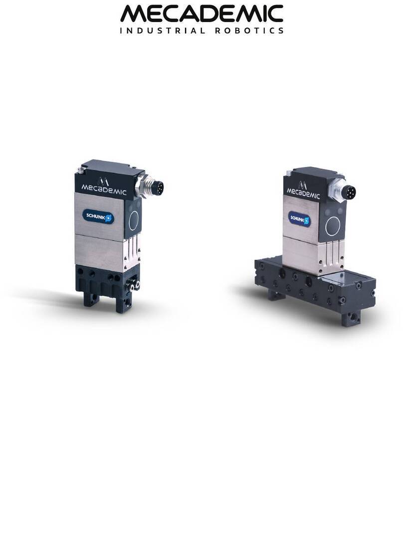
Mecademic MEGP 25E User manual

MEGP 25E/25LS ELECTRIC GRIPPERS
USER MANUAL
For Firmware Version 9.1.x
Document Revision: 2
September 12, 2022

The information contained herein is the property of Mecademic and shall not be reproduced
in whole or in part without prior written approval of Mecademic. The information herein
is subject to change without notice and should not be construed as a commitment by
Mecademic. This manual will be periodically reviewed and revised.
While every effort has been made to ensure accuracy in this publication, no responsibility
can be accepted for errors or omissions. Data may change, as well as legislation, and you
are strongly advised to obtain copies of the most recently issued regulations, standards, and
guidelines.
This document is not intended to form the basis of a contract.
© Copyright 2015–2022 Mecademic

MEGP25E/25LS User Manual (for rmware 9.1.x) i
CONTENTS
1. INTRODUCTION ..............................................................................................................................................1
1.1. Inside the box................................................................................................................................................1
2. TECHNICAL SPECIFICATIONS........................................................................................................................2
3. DESIGNING AND MOUNTING THE FINGERS ..................................................................................................3
3.1. MEGP25E mounting diagrams ....................................................................................................................3
3.2. MEGP25LS mounting diagrams ..................................................................................................................4
4. INSTALLING THE GRIPPER ............................................................................................................................6
4.1. Installation steps ..........................................................................................................................................6
4.2. Gripper LEDs ................................................................................................................................................8
5. OPERATING THE MECADEMIC GRIPPER........................................................................................................9
5.1. Firmware update ..........................................................................................................................................9
5.2. Safety ............................................................................................................................................................9
5.3. Maintenance .................................................................................................................................................9


MEGP25E/25LS User Manual (for rmware 9.1.x) iii
ABOUT THIS MANUAL
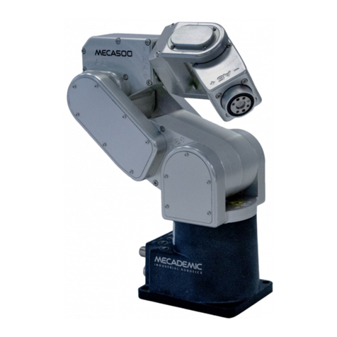
This user manual describes how to install the Mecademic electric grippers onto the Meca500 (R3)
industrial robot arm. You must read this manual thoroughly before installing or operating the
Mecademic grippers.
Symbol definitions
The following table lists the symbols that may be used in Mecademic documents to denote certain
conditions. Particular attention must be paid to the warning messages in this manual.
SYMBOL DEFINITION
NOTICE. Identifies information that requires special consideration.
!
CAUTION. Provides indications that must be respected in order to avoid equipment or work (data) on the
system being damaged or lost.
!
WARNING. Provides indications that must be respected in order to avoid a potentially hazardous
situation, which could result in injury.


MEGP25E/25LS User Manual (for rmware 9.1.x) 1
INTRODUCTION
1. INTRODUCTION
The MEGP 25E and MEGP 25LS grippers (Mecademic grippers) are electric parallel grippers developed
by Mecademic and Schunk, specifically for the Meca500 (R3) robot arm. The MEGP 25E (which replaces
MEGP 25) and MEGP 25LS use a removable connector cable.
Familiarity with the Meca500 robot and its user manual is required prior to installing and using
the grippers.
!
Improper installation of the grippers could seriously damage the Meca500 and the grippers
themselves. This grippers should therefore be used only by technical personnel who are familiar
with the Meca500.
1.1. Inside the box
Each of the two gripper models is supplied either individually or with the Meca500. In both cases, the
gripper is delivered in an anti-static bag containing the standard kit:
-1 MEGP 25E or 1 MEGP 25LS gripper;
-1 MGC-SS35 35-mm communication cable with straight connectors or
1 MGC-AA25 25-mm communication cable with 90° connectors;
-1 MEGP25-TAP adapter plate (made of unanodized aluminum) for attaching the gripper to the
Meca500’s mechanical interface (ange);
-4 M3X0.5 Torx at head screws of length 8 mm;
-2 M2.5X0.45 socket head screws of length 20 mm.
Note that Mecademic does not supply gripper ngers. These must be designed and machined
based on the workpiece that needs to be handled.
2 MEGP25E/25LS User Manual (for rmware 9.1.x)
TECHNICAL SPECIFICATIONS
2. TECHNICAL SPECIFICATIONS
Table 1 lists the main technical specifications for both electric grippers. Further specifications are
provided in the next section.
TECHNICAL SPECIFICATIONS
Characteristic Value for MEGP 25E Value for MEGP 25LS
Maximum weight per finger 0.02 kg 0.02 kg
Maximum gripping force 40 N 40 N
Recommended maximum
workpiece weight
0.2 kg 0.2 kg
Stroke per jaw 3 mm 24 mm
Repeatability 0.03 mm 0.02 mm
IP protection class 30 30
Power supply (nominal) 24 V, 0.14 A 24 V, 0.14 A
Noise emission < 70 dB < 70 dB
Housing Coated aluminum alloy, steel Coated aluminum alloy, steel
Total weight 0.106 kg 0.136 kg
Operating temperature 5° to 55°C 5° to 55°C
Operating humidity 10% to 95% RH (non-condensing) 10% to 95% RH (non-condensing)
Table 1: Technical specifications for Mecademic's electric grippers

MEGP25E/25LS User Manual (for rmware 9.1.x) 3
DESIGNING AND MOUNTING THE FINGERS
3. DESIGNING AND MOUNTING THE FINGERS
Fingers must be designed and installed before mounting a Mecademic gripper on the Meca500. Designs
must respect the measurements and maximum finger dimensions and loads provided in the following.
3.1. MEGP25E mounting diagrams
Figure1 shows the MEGP 25E dimensions and the adapter plate provided. Each finger must be attached
to the outer side of a gripper jaw using an M4X0.7 screw and two ⌀1.5 locating pins.
units: mm
25.4
70
14
18
7.5
4
11 ... 17
Adapter plate
for mounting on
Meca500’s flange
M4X0.7, thru
2
Ø1.5 H7, thru
2
X equally spaced
4
5
3
5
42.2
Figure1: MEGP 25E gripper dimensions
The maximum dimensions for the fingers and the maximum loads allowed on the gripper jaws are
shown in Figure2.

4 MEGP25E/25LS User Manual (for rmware 9.1.x)
DESIGNING AND MOUNTING THE FINGERS
z
x
x2 + z2 ≤ 30 mm
|My| ≤ 0.50 Nm
|Mz| ≤ 0.42 Nm
|Mx| ≤ 1.50 Nm
|Fx| ≤ 70 N
My
Mz
M
x
Fx
Figure2: Maximum nger dimensions and nger loads
3.2. MEGP25LS mounting diagrams
Figure3 shows the MEGP 25LS dimensions and the adapter plate provided. Each finger must be
attached to the outer side of a gripper jaw using an M4X0.7 screw and two ⌀1.5 locating pins.
42
70
4...52
7.8
17.1
Adapter plate
for mounting on
Meca500’s flange
28
16.4
units: mm
M4X0.7, thru
2
⌀1.5 H7, thru
2X equally spaced
4
5
3
5
20
Figure3: MEGP 25LS gripper dimensions
The maximum dimensions for the fingers and the maximum loads allowed on the gripper jaws are
shown in Figure4.

MEGP25E/25LS User Manual (for rmware 9.1.x) 5
DESIGNING AND MOUNTING THE FINGERS
z
x
|My| ≤ 0.50 Nm
|Mz| ≤ 0.42 Nm
|Mx| ≤ 1.30 Nm
|Fx| ≤ 70 N
My
Mz
Mx
Fx
x2 + z2 ≤ 32 mm
Figure4: Maximum nger dimensions and nger loads

6 MEGP25E/25LS User Manual (for rmware 9.1.x)
INSTALLING THE GRIPPER
4. INSTALLING THE GRIPPER
The Mecademic grippers are designed for only one type of installation; the assembly kit provided is for
that installation only. If mounting the gripper on the Meca500 flange differently, you must design and
machine your own adapter plate.
4.1. Installation steps
Before installing the gripper, the robot must be setup properly:
1. Turn the robot on using the power button on the robot base.
2. Open the robot interface and home the robot using the Home button, .
3. Activate all motors and release the brakes using the Activate button, .
4. Bring all joints to zero degrees using the MoveJoints (0,0,0,0,0,0) command.
5. Once all joints are zeroed, switch the robot off before proceeding to install the gripper.
!
The robot must be powered off before proceeding to install the gripper.
1
2
3
4
5
ZEROED
Figure5: Installing the Mecademic gripper
Install the gripper following the installation steps below, as shown in Figure5.
1. Make sure the flange is in zero position (screw at 12 o’clock).
2. Attach the adapter plate using the four M3X0.5X8 Torx flat head screws provided. Make sure to
install the plate in the proper orientation, as shown in Fig. 6.

MEGP25E/25LS User Manual (for rmware 9.1.x) 7
INSTALLING THE GRIPPER
M2.5X0.45M2.5X0.45
This side towards robot’s base
Figure6: Proper adapter plate orientation (when all joints are at zero degrees)
!
Use only the screws provided; longer screws will damage joint 6.
3. Attach the gripper to the adapter plate using the two M2.5X0.45 socket head screws provided.
4. Attach one end of the I/O cable to the gripper (both ends are identical).
5. Remove the screw cap from the I/O tool port on the robot (keep for future use). Attach the other
end of the cable to the port.
!
Using a dierent adapter plate or installing the gripper in any way other than as shown may
cause cable interferences. This may limit the range of motion of joint 6 and may result in
damage to the gripper and/or the robot.
Once the gripper is installed, you can start using the robot. When the Meca500 is activated, it will
automatically detect the gripper, and the green LED on the gripper will flash slowly as long as gripper is
activated.
The gripper is automatically homed when the robot is homed; it will fully open then close its fingers. This
homing procedure is necessary to detect the range of motion of the fingers (in case the design reduces
the nominal 6-mm range, for the MEGP25E or 48-mm range for the MEGP25LS). Once the gripper is
homed, the green LED on the gripper will light and will stay lit as long as the gripper is active.
Figure7 shows the MEGP 25 gripper installed and homed, in the case of both types of cables. Note that
the red LED is also on, because the gripper is fully closed, as will be described in the next section.

8 MEGP25E/25LS User Manual (for rmware 9.1.x)
INSTALLING THE GRIPPER
Figure7: MEGP 25E gripper installed and homed with the two dierent cables
4.2. Gripper LEDs
There are two LEDs on the gripper, just below the I/O tool port, one green and one red. Their behavior
indicates the gripper status with the Meca500 robot as follows:
LED description
LED Steady ON Slow Blink Fast Blink
RED Holding part or fully opened/
closed
Error n/a
GREEN Homed Activated Connected
Table 2: LED description
The button on the gripper, immediately below the two LEDs, is reserved for future use by
Mecademic technicians.

MEGP25E/25LS User Manual (for rmware 9.1.x) 9
OPERATING THE MECADEMIC GRIPPER
5. OPERATING THE MECADEMIC GRIPPER
The Mecademic grippers operate using the same commands as the Meca500. They can be opened or
closed using the GripperOpen and GripperClose commands. Gripping force can be configured using the
SetGripperForce(𝑓) command, where 𝑓 ranges from 5% to 100% (i.e., from 0 to approximately 40 N). By
default, the grip force limit is 40%. Gripping velocity can be set using the SetGripperVel(𝑣) command,
where 𝑣 is the finger velocity limit, ranging from 5% to 100% (approximately 100 mm/s). By default, the
finger velocity limit is 40%.
The gripper also has position control commands such as MoveGripper and SetGripperRange that allow
users to move the gripper or set a range limit. Consult the Meca500 Programming Manual for more
details on these commands.
5.1. Firmware update
If you upgrade the firmware of your robot (using the procedure described in the Meca500 User Manual)
while an MEGP 25E/25LS gripper is installed, the firmware of the gripper will be automatically updated.
Otherwise, you can update the firmware of your gripper separately by following the same procedure,
but selecting the file m500_exttools_*.update, instead of the file Meca500_E_LD_*.update.
5.2. Safety
The Mecademic grippers are designed with safety in mind, however, additional parts connected to (e.g.,
fingers) or held by the gripper may lead to risks of injuries. Pay attention to gripping force to avoid
ejecting workpieces or third-party hardware.
!
If the gripper is holding a part and left closed or opened for a long time, not at one of
the gripper extremities detected during homing, the gripper will become very hot. This is
normal.
5.3. Maintenance
As part of regular maintenance, it is important to ensure that the MEGP 25LS gripper travels the full
stroke every 1,000 cycles or at least once daily, whichever occurs first.

Contact Us
Mecademic
1300 St-Patrick Street
Montreal (Quebec) H3K 1A4
Canada
1-514-360-2205
1-833-557-6268 (toll-free in North America)
https://support.mecademic.com
© Copyright 2015–2022 Mecademic
Other manuals for MEGP 25E
1
This manual suits for next models
1
Table of contents
Other Mecademic Robotics manuals

Mecademic
Mecademic Meca500 User manual

Mecademic
Mecademic Meca500 R3 User manual

Mecademic
Mecademic Meca500 User manual

Mecademic
Mecademic Meca500 R3 User manual

Mecademic
Mecademic Meca500 R3 Owner's manual

Mecademic
Mecademic MEGP 25E User manual

Mecademic
Mecademic Meca500 (R3) Owner's manual

Mecademic
Mecademic Meca500 User manual

Mecademic
Mecademic Meca500 User manual

Mecademic
Mecademic Meca500 User manual