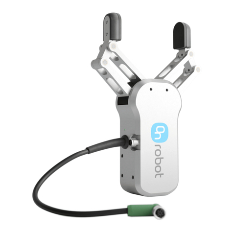
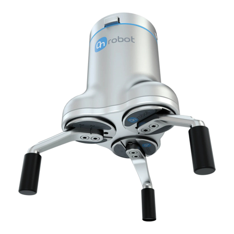
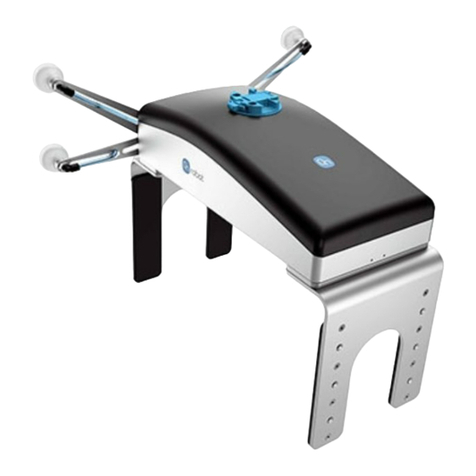
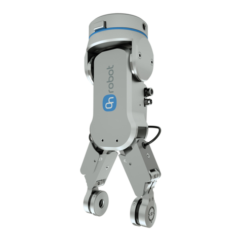
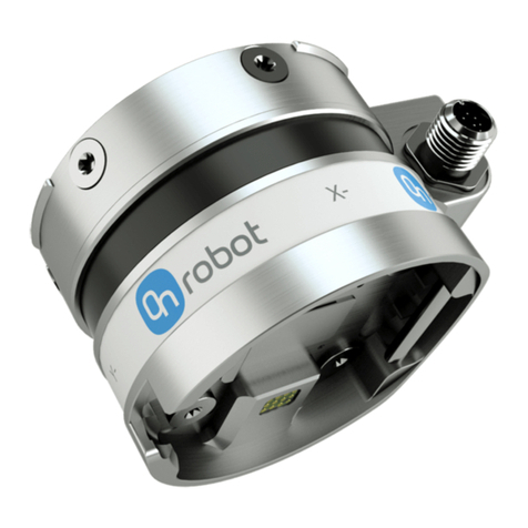
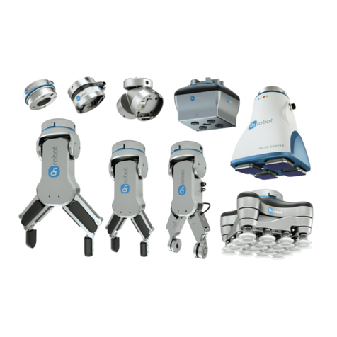
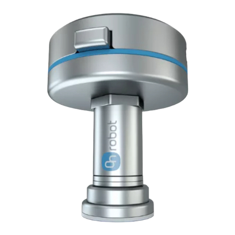
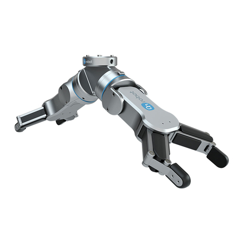
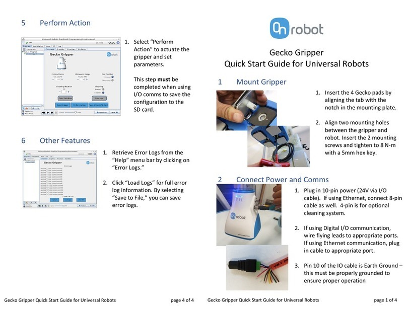
OnRobot Gecko Gripper Product information sheet

USER MANUAL
FOR NACHI ROBOTS
ORIGINAL INSTRUCTION (EN)
v1.05

Introduction
2
Contents
Contents.......................................................................................................................................2
1 Introduction.............................................................................................................................4
1.1 Important Safety Notice .....................................................................................................4
1.2 Scope of the Manual..........................................................................................................4
1.3 Naming convention............................................................................................................4
1.4 How to read the Manual.....................................................................................................5
2 Safety.......................................................................................................................................6
2.1 Intended Use.....................................................................................................................6
2.2 General Safety Instructions.................................................................................................7
2.3 Risk Assessment.................................................................................................................8
2.4 Environmental Safety.........................................................................................................8
2.5 PLd CAT3 Safety Function...................................................................................................9
3 Operation mode(s) .................................................................................................................10
Mode I - OnRobot EtherNet/IP.....................................................................................................12
4 Installation.............................................................................................................................13
4.1 Overview.........................................................................................................................13
4.2 Mounting........................................................................................................................ 13
4.2.1 Adapter(s).............................................................................................................. 13
4.2.2 Quick Changer options............................................................................................ 15
4.2.3 Tools......................................................................................................................17
4.3 Wiring ............................................................................................................................. 23
4.3.1 Tool data cable....................................................................................................... 23
1.1.2 Ethernet cable........................................................................................................ 24
4.3.2 Power supply..........................................................................................................25
4.4 Software setup ................................................................................................................ 27
4.4.1 Overview ............................................................................................................... 27
4.4.2 Configure the Compute Box as a Scanner................................................................. 27
4.4.3 Configure the Robot as an Adapter.......................................................................... 30
4.4.4 Upload the OnRobot functions to the robot............................................................. 32
5 Operation...............................................................................................................................33
5.1 Overview.........................................................................................................................33
5.2 List of functions ............................................................................................................... 34
Mode II - OnRobot WebLogic.......................................................................................................48
6 Installation.............................................................................................................................49
6.1 Overview.........................................................................................................................49

Introduction
3
6.2 Mounting........................................................................................................................ 49
6.2.1 Adapter(s).............................................................................................................. 49
6.2.2 Quick Changer options............................................................................................ 51
6.2.3 Tools......................................................................................................................53
6.3 Wiring ............................................................................................................................. 59
6.3.1 Tool data................................................................................................................ 59
6.3.2 Digital I/O wires......................................................................................................59
6.3.3 Ethernet cable........................................................................................................ 63
6.3.4 Power supply..........................................................................................................63
7 Operation...............................................................................................................................65
7.1 Overview.........................................................................................................................65
7.2 Ethernet Interface setup................................................................................................... 66
7.3 Web Client....................................................................................................................... 68
7.4 OnRobot WebLogic menu................................................................................................. 70
7.4.1 Browser.................................................................................................................70
7.4.2 Program Editor....................................................................................................... 71
8 Additional Software Options................................................................................................... 77
8.1 Compute Box...................................................................................................................77
8.1.1 Interfaces............................................................................................................... 77
8.1.2 Web Client............................................................................................................. 77
8.2 EtherNet/IP .....................................................................................................................96
8.2.1 Available connections and assembly instances .........................................................96
9 Hardware Specification......................................................................................................... 124
9.1 Technical sheets............................................................................................................. 124
9.2 Mechanical Drawings ..................................................................................................... 162
9.2.1 Adapter plate(s) ................................................................................................... 162
9.2.2 Mountings............................................................................................................ 165
9.2.3 Tools.................................................................................................................... 169
9.3 Center of Gravity............................................................................................................ 179
10 Maintenance........................................................................................................................ 181
11 Warranties........................................................................................................................... 184
11.1 Patents.......................................................................................................................... 184
11.2 Product Warranty .......................................................................................................... 184
11.3 Disclaimer...................................................................................................................... 184
12 Certifications........................................................................................................................ 185
1.2 Declaration of Incorporation........................................................................................... 191


Introduction
4
1Introduction
1.1 Important Safety Notice
DANGER:
You must read, understand, and follow all safety information in this
manual, and the robot manual and all associated equipment before
initiating robot motion. Failure to comply with safety information could
resultin deathor seriousinjury.
1.2 Scope of the Manual
The manual coversthe followingOnRobot products and its components:
Grippers
Version
GeckoGripper
v2
RG2
v2
RG2-FT
v2
RG6
v2
VG10
v2
VGC10
v1
Sensors
Version
HEX-E QC
v3
HEX-H QC
v3
Where applicable the combination of the products is also covered in the manual.
NOTE:
Generally, the products without the Quick Changer v2 interface, are not
in the scope of this manual.
1.3 Naming convention
In the usermanual Gecko Gripperis called Geckoonly.
The RG2 and RG6 namesas modelvariants are usedseparately ortogetherasRG2/6 if the informationis
relevantforboth variants.
The HEX-E QC and HEX-H QC names as model variants are used separately or together as HEX-E/H QC if
the information is relevantforboth variants.

Introduction
5
1.4 How to readthe Manual
The manual coversall OnRobotproductsand its components thatis available foryour robot.
To make it easyto follow whattype of product (orcombination) or componentis the given informationis
relevant for, the following visual highlights are used:
RG2
This is an instruction relevantforthe RG2 product only.
RG2-FT
This is an instruction relevantforthe RG2-FT productonly.
VG10
This is an instruction relevantforthe VG10 product.
All textwithoutthese visualmarks are relevantfor all productsor components.
For convenience, in each part that contains visual highlights (that span across pages) a table is provided
in the beginning, to guide you which page contains the relevant information for your product or
component:
RG2...................................................5
RG2-FT .............................................. 5
VG10.................................................5

Safety
6
2Safety
The robot integrators are responsible for ensuringthat the applicable safety laws and regulations in the
country concerned are observed and that any significant hazards in the complete robot application are
eliminated. This includes, but is not limited to:
•Performinga risk assessmentforthe complete robot system
•Interfacingothermachinesand additional safety devicesif defined by the risk assessment
•Settingup the appropriate safetysettingsin the robot software
•Ensuring that the userwill not modify anysafety measures
•Validating that the total robot system is designed and installed correctly
•Specifyinginstructionsfor use
•Marking the robot installation with relevantsigns and contact informationof the integrator
•Collecting all documentation in a technical file; including the risk assessment and thismanual
2.1 Intended Use
OnRobot tools are intended to be usedon collaborative robotsand light industrial robots with different
payloads depending onthe end-of-armtoolingspecifications.OnRobottools are normally use inpick-and-
place, palletizing, machine tending, assembly, quality testing and inspection and surface finishing
applications.
The end-of-armtoolingshouldonly operate underconditionsnoted in Technical sheets section.
Any use or application deviatingfromintended use is deemedto be impermissible misuse. Thisincludes,
but is not limited to:
•Use in potentially explosive atmospheres
•Use in medical and life critical applications
•Use before performingarisk assessment
•Use outside the permissible operationalconditionsand specifications
•Use close to a human’s head, face and eye area
•Use as a climbing aid

Safety
7
2.2 General Safety Instructions
Generally, all national regulations, legislations and laws in the country of installation must be observed.
Integration and use of the productmustbe done incompliance withprecautionsinthis manual.Particular
attention mustbe paid to the following warnings:
DANGER:
You must read, understand, and follow all safety information in this
manual, and the robot manual and all associated equipment before
initiating robot motion. Failure to comply with safety information could
resultin deathor seriousinjury.
The information in this manual does not cover designing, installing, and
operating a complete robot application, nor does it cover other
peripheral equipment that can influence the safety of the complete
system. The complete system must be designed and installed in
accordance with the safety requirements set forth in the standards and
regulations of the countrywhere the robotis installed.
Any safety informationprovidedinthis manual mustnotbe construedas
a warranty, by OnRobot A/S, that the robot application will not cause
injury or damage, even if robot application complies with all safety
instructions.
OnRobot A/S disclaims any and all liability if anyof OnRobottoolstooling
are damaged, changed or modified in any way. OnRobot A/S cannot be
heldresponsible forany damagescausedto any of OnRobottools tooling,
the robot, or any other equipment due to programming errors or
malfunctioningof anyof OnRobottools.
WARNING:
OnRobot tools are not allowed to be exposed to condensing conditions
when power ison orwhenconnectedtoarobot. If condensingconditions
appearduringtransportor storage, the productmustbe placed between
20 and 40 Celsiusdegreesfor24 hoursbefore poweris applied or before
connectedtoa robot.
It is recommended that OnRobot tools are integrated in compliance with the following guides and
standards:
•ISO 10218-2
•ISO 12100
•ISO/TR20218-1
•ISO/TS15066

Safety
8
2.3 Risk Assessment
The robot integrator must perform a risk assessment on the complete robot application. OnRobot tools
are onlycomponentsinarobotapplicationandthereforetheycan be only safelyoperatediftheintegrator
has considered the safety aspects of the whole application. OnRobot tools are designed with relatively
smooth and rounddesignwith a limited amountof sharp edgesandpinch points
In collaborative applications, the trajectory of the robot can play a significant safetyrole. The integrator
must consider the angle of contact with a human body, e.g. orientate OnRobot tools and workpieces so
that the contact surface in the direction of movementis as large as possible. It is recommendedthatthe
tool connectorsare pointed in the direction opposite tothe movement.
OnRobot A/S have identified the potential hazards listed below as significant hazards that must be
considered by the integrator:
•Objectsflyingfrom OnRobot tools due to loss of grip
•Objectsfalling downfrom OnRobottools due to loss of grip
•Injuries due to collisions between humans and workpieces, OnRobot tools tooling, robot or other
obstacles
•Consequencesdue to loosen of bolts
•Consequencesif OnRobot tools cable gets stuck to something
•Workpiece itself representsahazard
2.4 Environmental Safety
OnRobot A/S products must be disposed of in accordance with the applicable national laws, regulations
and standards.
The product is produced with restricted use of hazardous substances to protect the environment; as
defined by the EU RoHS Directive 2011/65/EU. These substances include mercury, cadmium, lead,
chromium VI, polybrominated biphenyls and polybrominated diphenylethers.
Observe nationalregistrationrequirements forimportersaccording to EU WEEE Directive 2012/19/EU.

Safety
9
2.5 PLd CAT3 Safety Function
RG2
RG6
A safety-rated functionhas been designed as two buttons at the two arms of the product, conforming to
ISO 13849-1 PLd CAT3.
This Safety Function has a max response time of 100 ms and a MTTF of 2883 years.
The behaviorof the safety systemisdescribedbelow:
If somethingactivates the twoSafety Buttons, see picture below, the safety controlsystem stops motion
of the twoarms of the product. Motion is then preventedaslong as one or both of the two buttons are
activated.
If this happens while running the robot program, user can detect this condition with the help of the
provided statusinformationand execute anynecessary stepon the robot.
To come back to normal operationwith the gripper there are providedcommands to reset the gripper.
CAUTION:
Before resetting the gripper always make sure that no part will be
dropped due to the loss of gripper power. If Dual Quick Changer is used
it will cycle the powerforboth sides.
For furtherdetailsreferto the Operationsection.
PLd CAT3 Safety Buttons

Operationmode(s)
10
3Operation mode(s)
There are two alternative modes howthe device(s) couldbe used:
Modesof Operation
OnRobot EtherNet/IP
required in the robot: EtherNet/IP
module
OnRobot WebLogic
required in the robot: digital I/O module
OnRobot EtherNet/IP
This mode uses the EtherNet/IP industrialnetwork protocolto operate the grippers/sensor.
EtherNet/IP is afieldbus thatuses the standard Ethernet networking (simpleUTP cable, standardnetwork
switch can be used, etc.).
The Compute Box implements an EtherNet/IP Scanner(masterdevice) and requires the robot controller
to implement an EtherNet/IP Adapter(slave device)tooperate.
With configurable cycle time (e.g.: 8ms) the Computer Box can "read" and "write" to the robot so the
grippers/sensor canbe controlled or monitored.
The communicationis implemented viaEtherNet/IPAssembly Instancesthatare created foreach product
or product combination (e.g.: RG2+VG10). The instances are containing a set of words (16-bit data) that
can be used to control/monitor the grippers/sensor (e.g.: the 4th word of the Assembly Instance 104 is
the Actual Width for the RG2/6).
There are global functionsprovided (on the USBstick) to make it easy to accessthe productfeatures.
OnRobot WebLogic
This mode allows simple Digital I/O communication to be usedto operate the grippers/sensor.
For example the Compute Box couldbe easily programmedto:
•when one of the robotdigital outputs is set to HIGH, then the RG2 gripper opens to77mm
•or whenthe force values measured withthe HEX-E QC reach 50N, the Compute Box sends a HIGH
digital outputto the robot.
The Compute Box has 8 digital inputs and 8 digital outputs that can be freely configured forany "logic".
In this waythe user can configure:
•eight gripper/sensor controlling functionality (e.g.: set width to X, close, zero, set preload, etc.)
•and eightgripper/sensormonitoringfunctionality(e.g.: is grip detected, ispreload> 50N, etc.).
Furthermore, the "logic" can be complex, like:
•is grip detected ANDforce >20N

Operationmode(s)
11
These "logics"can be programmedthroughtheCompute Box'sweb interfacecalled WebClient. Itrequires
only a normal computerwith a browser.
In this documentboth modes of operation will be covered and will be referred toas:
•OnRobot EtherNet/IP
•OnRobot WebLogic
Mode I - OnRobot EtherNet/IP......... 12
Mode II - OnRobot WebLogic........... 48

Operationmode(s)
12
Mode I - OnRobot EtherNet/IP

Installation
13
4Installation
4.1 Overview
For a successfulinstallation the followingsteps will be required:
•Mountthe components
•Wire the cables
•Setup the software
In the followingsections, these installation stepswill be described.
4.2 Mounting
Required steps:
•Mountthe robot dependentadapter
•Mountthe Quick Changeroption
•Mountthe tool(s)
In the following three subsections these three mountingsteps willbe described.
4.2.1 Adapter(s)
For CZ10,MZ03EL, MZ07 models
Adapter I
1
M5x8 screws (ISO14580 A4-
70)
2
OnRobot adapter flange
(ISO9409-1-50-4-M6)
3
Dowel pin Ø6x8 (ISO2338
h8)
4
Robottool flange
Use 5 Nm tighteningtorque.
For MZ04 models

Installation
14
Adapter J
1
M5x8 screws (ISO14580 A4-
70)
2
OnRobot adapter flange
(ISO940-1-50-4-M6)
3
Dowelpin Ø6x8(ISO2338 h8)
4
Robottool flange
Use 5 Nm tightening torque.

Installation
15
4.2.2 Quick Changer options
Quick Changer -
Robot Side
Quick Changer - Robot Side
1
M6x8mm (ISO14580 8.8)
2
Quick Changer(ISO9409-1-50-4-M6)
3
Dowelpin Ø6x10 (ISO2338 h8)
4
Adapter/ Robot tool flange (ISO 9409-
1-50-4-M6)
Use 10 Nm tightening torque.
Dual Quick Changer
Dual Quick Changer
1
M6x20mm (ISO14580 8.8)
2
Dual Quick Changer
3
Dowelpin Ø6x10 (ISO2338 h8)
4
Adapter/ Robot tool flange (ISO
9409-1-50-4-M6)
Use 10 Nm tightening torque.

Installation
16
HEX-E/H QC
HEX-E/H QC
1
HEX-E/H QC sensor
2
M4x6mm (ISO14581 A4-
70)
3
M6x8mm (NCN20146 A4-
70)
4
HEX-E/H QC adapter
5
Adapter/ Robot tool
flange (ISO 9409-1-50-4-
M6)
Use 1.5 Nm tightening torque.
for M4x6mm
Use 10 Nm tighteningtorque. for
M6x8mm

Installation
17
4.2.3 Tools
Gecko.............................................. 17
RG2................................................. 18
RG2-FT ............................................ 19
RG6................................................. 20
VG10............................................... 21
VGC10............................................. 21
Quick Changer - Tool side................. 22
Gecko
Step 1:
Move the tool close to the Quick
Changeras illustrated.
The hook mechanism (rod and hook
tongue) will keepthe lower part locked
once mounted.
Step 2:
Flip the tool until it is fully mated, and
you hear a clicking sound.
To unmount the tool, press the aluminum
button on the Quick Changer and repeat the
steps in the reverse order.
CAUTION:
With a Dual Quick Changer the Gecko Gripper can only be mounted on
the Secondary (2) side. Mountingon the Primary (1) side will prevent the
devicesto functioncorrectly.

Installation
18
RG2
Step 1:
Move the tool close to the Quick Changer
as illustrated.
The hook mechanism (rod and hook
tongue) will keep the lower part locked
once mounted.
Step 2:
Flip the tool until it is fully mated, and you
heara clicking sound.
To unmountthe tool, press the aluminumbutton
on the Quick Changerand repeatthe stepsin the
reverse order.
To change the relative angle of the gripper
to the Quick Changer:
•first remove the fourM4x6 screws
•tilt the gripperbetween -90° and 90°
•then put the four M4x6 screws back
and use 1.35 Nm tightening torque
to fix it.
WARNING:
Never use the device while any of the four M4x6 screws are removed.

Installation
19
RG2-FT
Step 1:
Move the tool close to the Quick Changer
as illustrated.
The hook mechanism (rod and hook
tongue) will keep the lower part locked
once mounted.
Step 2:
Flip the tool until it is fully mated, and you
heara clicking sound.
To unmountthe tool, press the aluminumbutton
on the Quick Changerand repeatthe stepsin the
reverse order.
To change the relative angle of the gripper
to the Quick Changer:
•first remove the fourM4x6 screws
•tilt the gripperbetween -60°and 90°
•then put the four M4x6 screws back
and use 1.35 Nm tightening torque
to fix it.
WARNING:
Neveruse the device while any of the four M4x6 screwsare removed.

Installation
20
RG6
Step 1:
Move the tool close to the Quick
Changeras illustrated.
The hook mechanism (rod and hook
tongue) will keepthe lower part locked
once mounted.
Step 2:
Flip the tool until it is fully mated, and
you hear a clicking sound.
To unmount the tool, press the aluminum
button on the Quick Changer and repeat the
steps in the reverse order.
To change the relative angle of the gripper
to the Quick Changer:
•first remove the fourM4x6 screws
•tilt the gripperbetween -90° and 90°
•then put the four M4x6 screws back
and use 1.35 Nm tightening torque
to fix it.
WARNING:
Never use the device while any of the four M4x6 screws are removed.
Other manuals for Gecko Gripper
2
This manual suits for next models
7
Table of contents
Other OnRobot Robotics manuals

OnRobot
OnRobot HEX-E QC User manual

OnRobot
OnRobot Gecko SP1 User manual

OnRobot
OnRobot DOOSAN Gecko Gripper User manual

OnRobot
OnRobot UR CB3 Series User manual

OnRobot
OnRobot SG User manual

OnRobot
OnRobot Gecko Gripper User manual

OnRobot
OnRobot Gecko Gripper User manual

OnRobot
OnRobot RG6 User manual

OnRobot
OnRobot 2FGP20 User manual

OnRobot
OnRobot RG2 User manual