Mecal FAKRA User manual
Miniapplicator Operating instructions Created by Mecal s.r.l.
1
Mecal Srl
Sede legale e Stab.: Strada per Felizzano, 18 - 15043 Fubine (Al)
Tel. (0131) 792792 - Fax (0131) 792733/792734Cap. Soc. € 500.000 int.vers.
Registro delle Imprese di Alessandria n. 11690 - CCIAA Alessandria - REA N. 153887 - N. Meccanografico AL002563
Codice Fiscale 01328270069 – Codice ISO: IT - Partita Iva: 01328270069
FAKRA OUTER DIRITTO (maschio e femmina) PER CAVO:
RG174, RTK031, RG58/59
ISTRUZIONI OPERATIVE MINIAPPLICATORE RESTYLING
PR
OG
ETT
O
FAKRA
FAKRA PROJECT RESTYLING OPERATING
IN
S
TR
UC
TI
O
N
S

Miniapplicator Operating instructions Created by Mecal s.r.l.
2
MECAL s.r.l.
Strada per Felizzano 18
Fubine (AL) 15043
Italy
Phone: +39 0131 792792
Fax: +39 0131 792733
Web : www.mecal.net
Preferred by Professional EDS Specialist
Queste istruzioni sono state create in data ottobre 2009, possono essere soggette a modifiche.
Inoltre MECAL dichiara che le immagini riportate in questo manuale potrebbero non essere
aggiornate con modifiche tecniche apportate sui prodotti per migliorie o richieste particolari.
Preferred by Professional EDS Specialist
These instructions have been created in october 2009 and Mecal reserves the right to modify it at
anytime. Furthermore, the pictures shown might not represent the latest configurations or special
versions manufactured to satisfy special customers needs.

Miniapplicator Operating instructions Created by Mecal s.r.l.
3
Indice
1) AVVERTENZE IMPORTANTI........................................................................................6
1.1) SIMBOLOGIA.............................................................................................................................7
2) IDENTIFICAZIONE .............................................................................................................8
3) DESCRIZIONE DEL PRODOTTO.................................................................................9
3.1) CARATTERISTICHE TECNICHE ................................................................................................10
4) ISPEZIONE ALLA CONSEGNA ...................................................................................11
5) INSTALLAZIONE................................................................................................................12
5.1) INSTALLAZIONE MINIAPPLICATORE ........................................................................................12
5.2 ) COLLEGAMENTO PNEUMATICO ED ELETTRICO.....................................................................14
5.3) SCHEMA PNEUMATICO............................................................................................................15
5.4) INSERIMENTO TERMINALE ......................................................................................................16
6) REGOLAZIONI.....................................................................................................................18
6.1) REGOLAZIONE GHIERA...........................................................................................................18
6.2) REGOLAZIONE PASSO TERMINALE .........................................................................................20
6.2.1) Regolazione sensore avanzamento terminale..................................................................22
6.2.2) Sensore controllo bandella terminale..............................................................................23
6.3) REGOLAZIONE TERMINALE SU ASSE DI AGGRAFFATURA........................................................24
6.4) ALLINEAMENTO TERMINALE CON MATRICI..............................................................................26
6.4.1) Matrici superiori..............................................................................................................26
6.4.2) Matrici inferiori...............................................................................................................27
6.4.3) Lama di taglio inferiore...................................................................................................29
6.5) REGOLAZIONE PRESSORE DI TAGLIO ANTERIORE..................................................................30
6.6) BLOCCAGGIO TERMINALE.......................................................................................................33
6.6.1) Pressore di bloccaggio....................................................................................................33
6.6.2) Sensore blocco terminale, sensore terminale mancante..................................................34
6.7) REGOLAZIONE CENTRAGGIO POSTERIORE ............................................................................35
6.8) REGOLAZIONE POSIZIONE OUTER E GUIDA INNER.................................................................37
6.8.1) Regolazione sensore per posizione Outer........................................................................39
6.8.2) Allineamento guida centraggio con supporto Inner........................................................40
6.9) GRUPPO SENSORE POSIZIONE “INNER”.................................................................................42
6.9.1) Regolazione supporto posizione Inner.............................................................................42
6.9.2) Regolazione sensore posizione Inner...............................................................................44
6.9.3) Verifica anomalie durante inserimento outer su inner....................................................45
6.10) REGOLAZIONE PINZE BLOCCAGGIO CAVO “INNER”..............................................................46
6.10.1) Regolazione chiusura pinza bloccaggio cavo “Inner” .................................................48
6.10.2) Regolazione sensore pinza bloccaggio cavo “Inner”...................................................49
7) CICLO DI LAVORO (MANUALE)...............................................................................50
8) POSIZIONE CAMMA.........................................................................................................58
8.1) CAMME SU RESTYLING PNEUMATICO (MRSP).....................................................................58
9) MANUTENZIONE ...............................................................................................................59
9.1) PARTICOLARI DI RICAMBIO .....................................................................................................59
9.2) ESEMPIO DI DOCUMENTAZIONE..............................................................................................60
9.3) PULIZIA E LUBRIFICAZIONE.....................................................................................................62
9.4) IMMAGAZZINAMENTO..............................................................................................................63

Miniapplicator Operating instructions Created by Mecal s.r.l.
4
9.5) SOSTITUZIONE PARTICOLARI DI RICAMBIO.............................................................................64
9.5.1) Sostituzione matrici di aggraffatura e taglio...................................................................64
9.5.2) Sostituzione supporto terminale “Inner”........................................................................66
9.6) DEMOLIZIONE E SMALTIMENTO ..............................................................................................68
10) RICERCA GUASTI E RISOLUZIONE PROBLEMI ..........................................69
11) ASSISTENZA POST VENDITA...................................................................................73

Miniapplicator Operating instructions Created by Mecal s.r.l.
5
Index
1) Important warnings....................................................................................................................6
1.1) Symbology ................................................................................................................................7
2) Identification ...............................................................................................................................8
3) Product description....................................................................................................................9
3.1) Technical data........................................................................................................................10
4) Inspection upon delivery........................................................................................................11
5) Installation..................................................................................................................................12
5.1) Miniapplicator Installation...................................................................................................12
5.2) Pneumatic and elettrical connection....................................................................................14
5.3) Pneumatic drawing................................................................................................................15
5.4) Terminal insertion.................................................................................................................16
6) Adjustments...............................................................................................................................18
6.1) Continuos adjusting head .....................................................................................................18
6.2) Feeding adjustment ...............................................................................................................20
6.2.1) Sensor adjustment advancement terminal .............................................................22
6.2.2) Sensor control terminal strip .....................................................................................23
6.3) Terminal positioning on the crimping axis..........................................................................24
6.4) Terminal alignment matrix...................................................................................................26
6.4.1) Wire and insulation crimper.......................................................................................26
6.4.2) Anvil and terminal support.............................................................................................27
6.4.3) Lower cutting blade.....................................................................................................29
6.5) Adjusting cutting front..........................................................................................................30
6.6) Locking terminal....................................................................................................................33
6.6.1) Presser locking............................................................................................................33
6.6.2) Terminal sensor block, terminal sensor missing....................................................34
6.7) Adjusting rear centering.......................................................................................................35
6.8) Position Adjustment of Outer Inner guide..........................................................................37
6.8.1) Adjust sensor position Outer.....................................................................................39
6.8.2) Alignment centering guide with Inner support........................................................40
6.9) Group position Inner sensor................................................................................................42
6.9.1) Support inner position adjustment............................................................................42
6.9.2) Sensor Inner position adjustment.............................................................................44
6.9.3) Verification abnormalities during insertion outer to inner .....................................45
6.10) Adjusting pliers on media contact "Inner"......................................................................46
6.10.1) Adjustment closing pliers locking cable "Inner" ...................................................48
6.10.2) Sensor adjustment locking pliers cable "Inner"....................................................49
7) Work cycle (Man.)...................................................................................................................50
8) Cam Position.............................................................................................................................58
8.1) Pneumatic Restyling cam (MRSP).......................................................................................58
9) Maintenance ..............................................................................................................................59
9.1) Spare parts .............................................................................................................................59
9.2) Example of the documentation.............................................................................................60
9.3) Cleaning and lubrication.......................................................................................................62
9.4) Storage....................................................................................................................................63
9.5) Substitution spare parts........................................................................................................64
9.5.1) Substitution crimping and cutting .............................................................................64
9.5.2) Substitution contact support "Inner”.........................................................................66
9.6) Demolition and disposal........................................................................................................68
10) Problem shooting...................................................................................................................69
11) After sales service..................................................................................................................73
Miniapplicator Operating instructions Created by Mecal s.r.l.
6
1) Avvertenze importanti
1) Important warnings
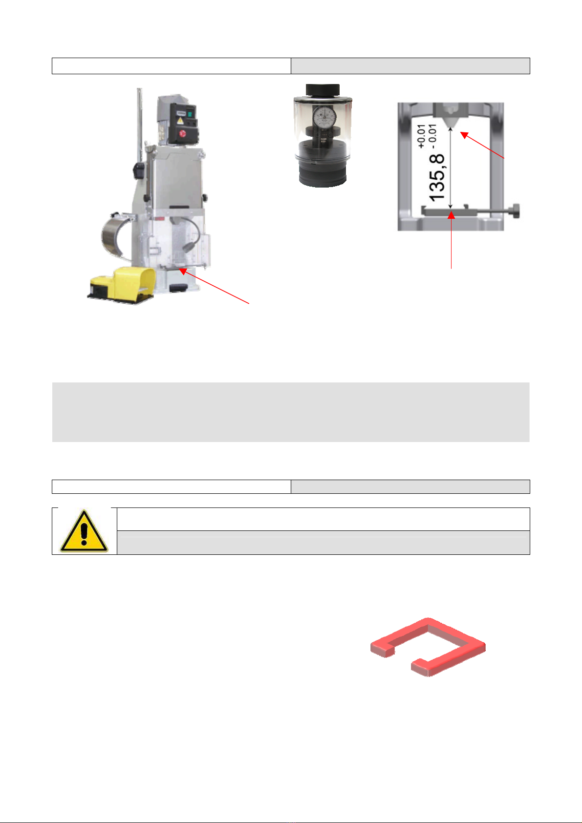
Fase Fase Operazione - Operation
• Verificare la corretta
altezza di taratura
della pressa al punto
morto inferiore P.M.I.
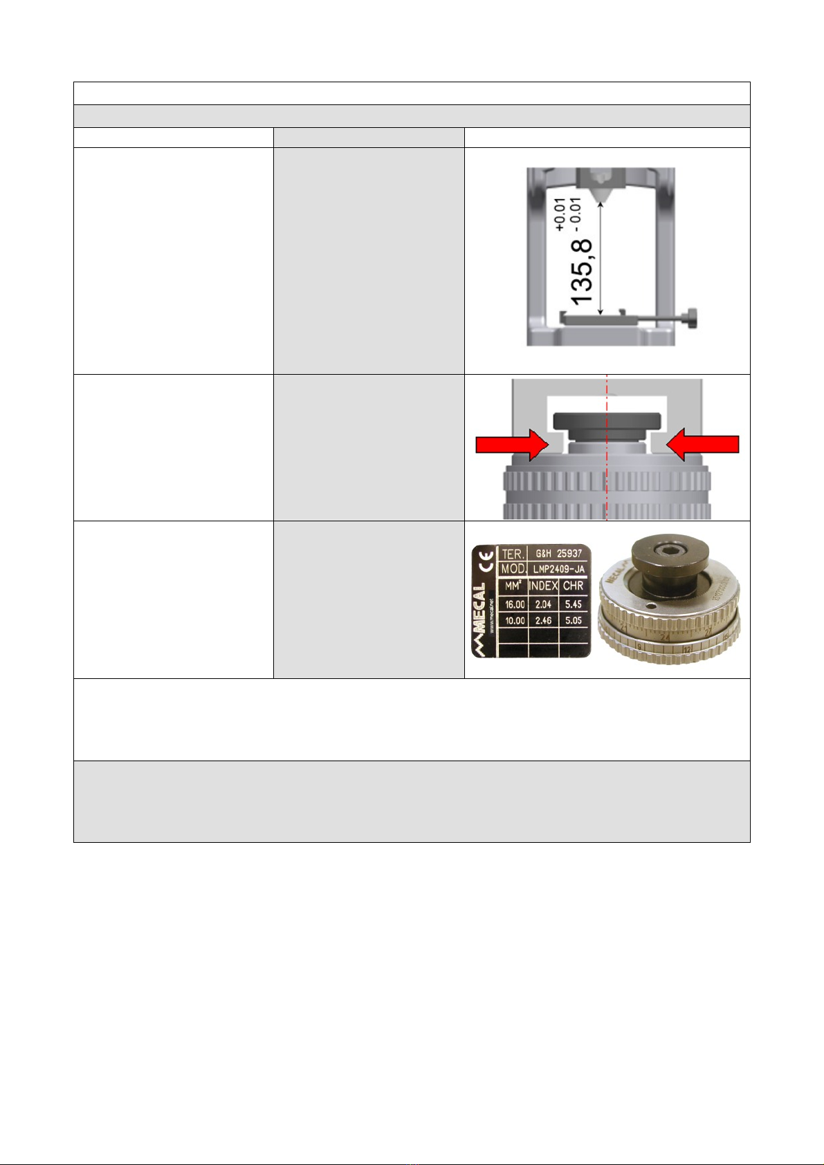
pari a mm 135,8.
• Verify the press
crimping height
setting : 135,8 mm at
Bottom Dead Center.
• Verificare
assolutamente
l’allineamento
dell’asse pressa con
l’attrezzo di lavoro
• Carefully verify that
the press and the
applicator’s axis are
perfectly in line
• Posizionare la ghiera
di regolazione
secondo le indicazioni
riportate sulla
targhetta di
identificazione
• Set the top ring of
the continuous
adjusting head
according with the
data on the
identification plate
N.B. Dopo aver installato il miniapplicatore, far compiere manualmente alla pressa un ciclo completo
per mezzo dell’apposita chiave o volantino, per verificare che:
• Non ci siano impedimenti al libero funzionamento del miniapplicatore
• Il terminale sia posizionato correttamente in asse sull’incudine e con i particolari di aggraffatura e di
taglio
Note: After having installed the miniapplicator, cycle manually the press by means of the
supplied wrench in order to check that:
• The applicator turns smoothly without sticking in any way
• The terminal is correctly placed on the anvil, in line with the same and the other crimping and cutting
parts

Miniapplicator Operating instructions Created by Mecal s.r.l.
7
1.1) Simbologia 1.1) Symbology
ATTENZIONE: questo simbolo viene utilizzato per indicare alcune parti del manuale in
cui vengono riportate operazioni che devono essere lette con attenzione
WARNING: this symbol identifies any portion of this manual that should be carefully
read and understood
STOP: questo simbolo viene utilizzato per indicare alcune parti del manuale in cui
vengono riportate operazioni che devono essere controllate e, quindi, non proseguire. Si
potrebbe causare un danno meccanico alla macchina.
STOP: this symbol identifies all the situations where the operator is supposed to stop
and procede to the suggested checks before resuming the operation.
Ignoring it would mean causing damages to the equipment.
INFORMAZIONI: questo simbolo viene utilizzato per indicare alcune parti del manuale in
cui vengono riportate note di informazioni generiche
INFORMATION: this symbol identifies any portion of this manual where generic
informations and suggestions could be found
RICICLO: questo simbolo indica le parti della macchina o dell’imballo che devono essere
riciclate o smaltite secondo le norme vigenti
RECYCLING: this symbol identifies the parts of the product and its package that must be
recycled or disposed in accordance with the local rules.
SALVATAGGIO: questo simbolo viene utilizzato per indicare alcune parti del manuale in
cui vengono riportate note o consigli dove occorre effettuare un salvataggio dei dati
dell’attrezzatura
SAVE: this symbol identfies any portion of this manual that refers to data that should be
saved.
Miniapplicator Operating instructions Created by Mecal s.r.l.
8
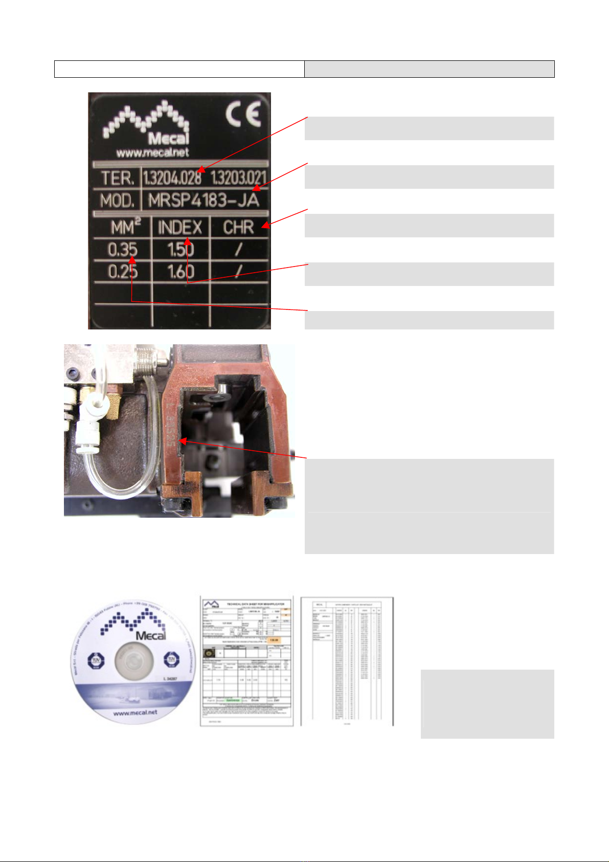
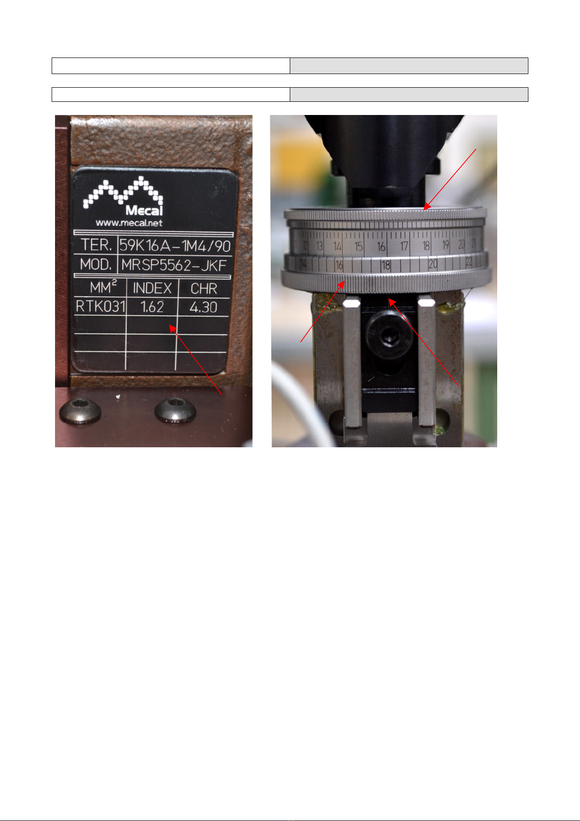
2) Identificazione 2) Identification
P/N terminale del cliente o fornitore
Terminal customer reference (Part Nr.)
Modello miniapplicatore relativo al P/N del terminale
Mecal’s Miniapplicator code (related to the above
mentioned terminal)
Altezza di aggraffatura (CHR)
Crimping Height (CHR)
Posizione della ghiera (INDEX) riferita all’altezza di
aggraffatura (CHR)
Position of the top adjusting ring (INDEX) allowing to
obtain the crimping height (CHR) written on the right
Minima e massima sezione di cavo
Wire cross section (min & max)
Numero di serie del miniapplicatore
Miniapplicator’s serial number
CD con numero di serie e
documentazione completa
di Data Sheet, distinta base
ed esplosi
CD containing all the
applicator’s relevant data,
including component list
and drawings

Miniapplicator Operating instructions Created by Mecal s.r.l.
9
3) Descrizione del prodotto 3) Product description
La famiglia dei Miniapplicatori serve per aggraffare i terminali concatenati con cavi di differenti sezioni.
Vengono impiegati, soprattutto, per terminali con spessore fino a 1,2 mm e passo minore di 41 mm. Nuova
concezione di applicatore realizzato in corpo di ghisa di fusione capace di supportare una personalizzazione
laterale oppure frontale, facile sostituzione dei particolari di ricambio mediante fissaggio frontale dei pezzi,
ampia accessibilità e facilità per le varie regolazioni. Il miniapplicatore è equipaggiato di un conta pezzi a
sette cifre non resettabile per il controllo delle parti d’usura. La Ghiera per la regolazione dell’altezza di
aggraffatura è di tipo in continuo con una risoluzione di 0,01mm e un campo di regolazione di 2,7mm. Viene
fornito corredato da una serie di documentazione elettronica archiviata su un CD che include una pagina con
i dati relativi alla macchina (modello, numero di matricola, valori riscontrati durante il collaudo), la distinta
tecnica con i codici ed i riferimenti di tutti i particolari montati e l'esploso. Su richiesta è possibile ottenere
uno studio più approfondito dell’aggraffatura che comprende la capability e la micrografia della sezionatura
di un terminale aggraffato.
La famiglia include anche una versione pneumatica per terminali che presentono uno svolgimento della
bobina da destra verso sinistra e da sinistra verso destra e una versione manuale con slitta per poter
aggraffare terminali sciolti (non legati fra loro)
The Miniapplicator family serves to crimp the terminals concatenated with cables of different sections. Are
used, above all, terminals with a thickness up to 1.2 mm and wheelbase of less than 41 mm. New concept of
applicator body made of cast iron casting that supports customization side or front, easy replacement of
specific parts by fastening the front of the pieces, broad accessibility and ease for a variety of settings. The
Miniapplicator is equipped with a seven-digit pieces has not reset for the control of wear parts. The ring for
adjusting the height of crimping type is continuous with a resolution of 0.01 mm and an adjustment range of
2.7 mm. It comes with a number of electronic documents stored on a CD that includes a page with data on
the machine (model number, the values found during testing), the bill with technical codes and references of
all the details assembled and exploded. On request you can get a more detailed study dell'aggraffatura
which includes the capability of cutting and micrograph of a terminal crimped. The family also includes a
pneumatic version for terminals that have a middle of the coil from right to left and from left to right and a
manual version with slide to loose crimp terminal (not related to each other)
Applicazione Miniapplicatore FAKRA su presse – FAKRA Miniapplicator application
on the presses
TT P107C P40 P80 P120 P200
MRSP FAKRA
Questo tipo di miniapplicatore è funzionante sulle presse indicate solamente corredato
dell’apposita centralina di comando con PLC (codice 871430012)
This type of applicator is suitable only working on presses equipped with the special
control unit PLC (871430012 code)
Miniapplicator Operating instructions Created by Mecal s.r.l.
10
3.1) Caratteristiche tecniche 3.1) Technical data
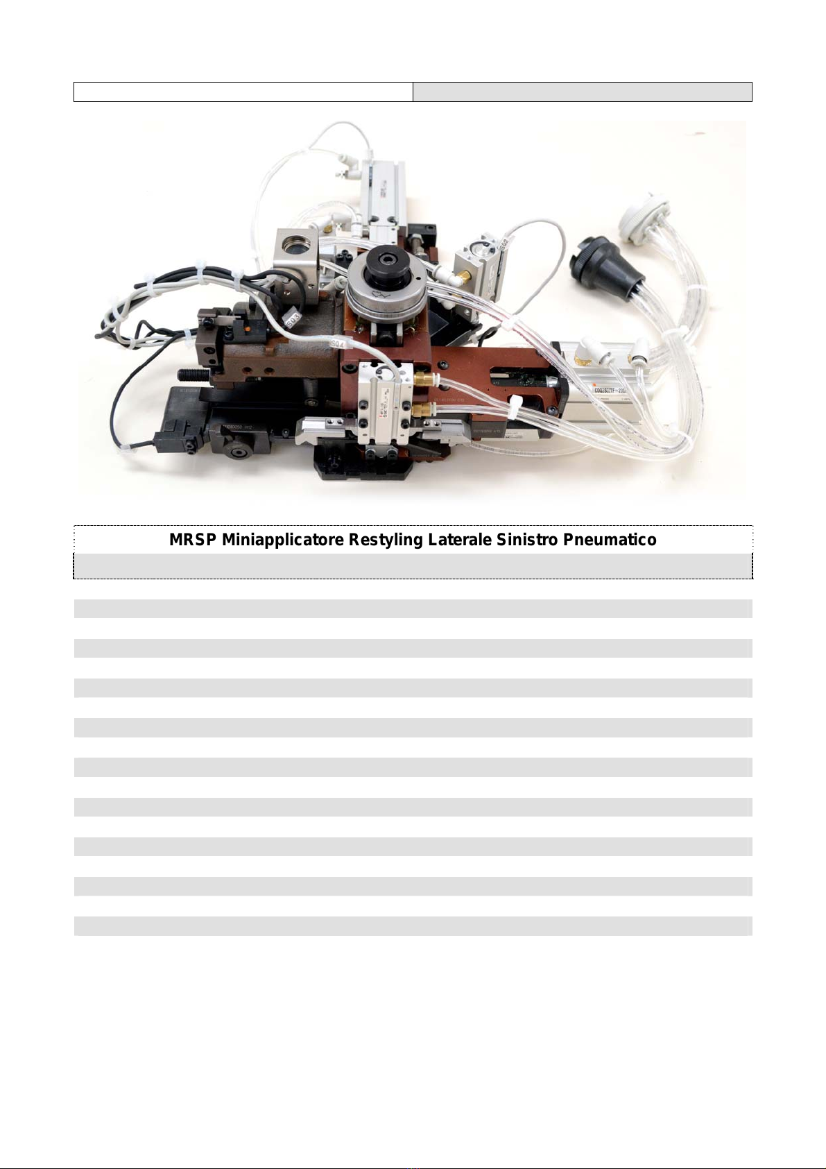
MRSP Miniapplicatore Restyling Laterale Sinistro Pneumatico
MRSP Restyling Pneumatic Left side Feed miniapplicator
Modello: MRSP
ID: MRSP
Altezza di lavoro al PMI: 135,8mm
Crimping height: 135,8mm
Corsa di lavoro pressa: 40 / 30mm
Stroke: 40 / 30mm
Passo terminale: Max. corsa 35mm
Terminal pitch: Max. stroke 35mm
Spessore terminale: 0.30mm (0.011”)
Terminal thickness: 0.30mm (0,011")
Sezione cavo: RG174, RTK031, RG58/59
Wire section: RG174, RTK031, RG58/59
Sistema di alimentazione: aria 5/6 Bar
Feeding system: air pressure 5/6 Bar
Peso: 7,8 kG ( 17,2 lb)
Weight: 7,8 kG ( 17,2 lb)
Dimensioni: W320xH145,5xD370 W12,5"xH5,72"xD14,5"
Dimension: W320xH145,5xD370 W12,5"xH5,72"xD14,5"

Miniapplicator Operating instructions Created by Mecal s.r.l.
11
4) Ispezione alla consegna 4) Inspection upon delivery
L’applicatore viene consegnato in apposito imballo
contenente:
• Un Miniapplicatore
• Campioni di aggraffatura creati per il collaudo
• CD istruzioni e uso manutenzione
(Optional) su richiesta:
• Kit particolari di ricambio
• Foto sezione terminale aggraffato (allegato a
file si CD)
• Capability (allegato a file su CD)
Alla consegna:
• Verificare che l’applicatore non abbia
subito danni e non vi siano parti mancanti
controllando il documento di
accompagnamento
• In caso di anomalia avvisare Mecal
entro e non oltre i 10 giorni dalla data di
ricevimento
• L’imballaggio deve essere smaltito
come da norme vigenti, non disperdere
nell’ambiente: rivolgersi ad aziende
autorizzate per lo smaltimento.
The applicator is delivered protected by a dedicated
packaging, which contains:
• One Miniapplicator
• Some crimping samples
• CD
(Optional) upon request
• Kit of spare parts
• One picture of the terminal cross section (on
CD)
• One capability study (on CD)
Upon receiving the applicator:
• Check for transportation damages and
make sure that all the parts listed are there
• In case of damages and/or missing
parts, please notify Mecal within 10 days
from receiving the applicator
• The packge should be disposed
according the local rules.
Miniapplicator Operating instructions Created by Mecal s.r.l.
12
5) Installazione 5) Installation
A
Strumento di taratura Pressa
STP
Shut height gauge STP
A
Questa operazione preliminare è molto importante per il corretto funzionamento. Pulire la superficie di
staffaggio “A” garantendo un buon piano di appoggio fra la base della pressa e quella del miniapplicatore.
Verificare con apposito Strumento di Taratura STP l’altezza di lavoro corretta che deve essere, al P.M.I. di
135,8mm (±0.01mm).
N.B. MECAL fornisce le macchine collaudate e tarate.
These preliminary operations are of the utmost importance to guarantee the best service from the applicator.
Clean carefully the coupling surface “A” to grant the correct mating of the applicator with the press locking
base. Using the specific setting tool, make sure that, with the ram ai its Bottom Dead Center, the distance
between the applicator locking base and the T coupling is mm 135,8 (±0.01mm)
Note: MECAL presses are delivered already in compliance with the above mentioned setting
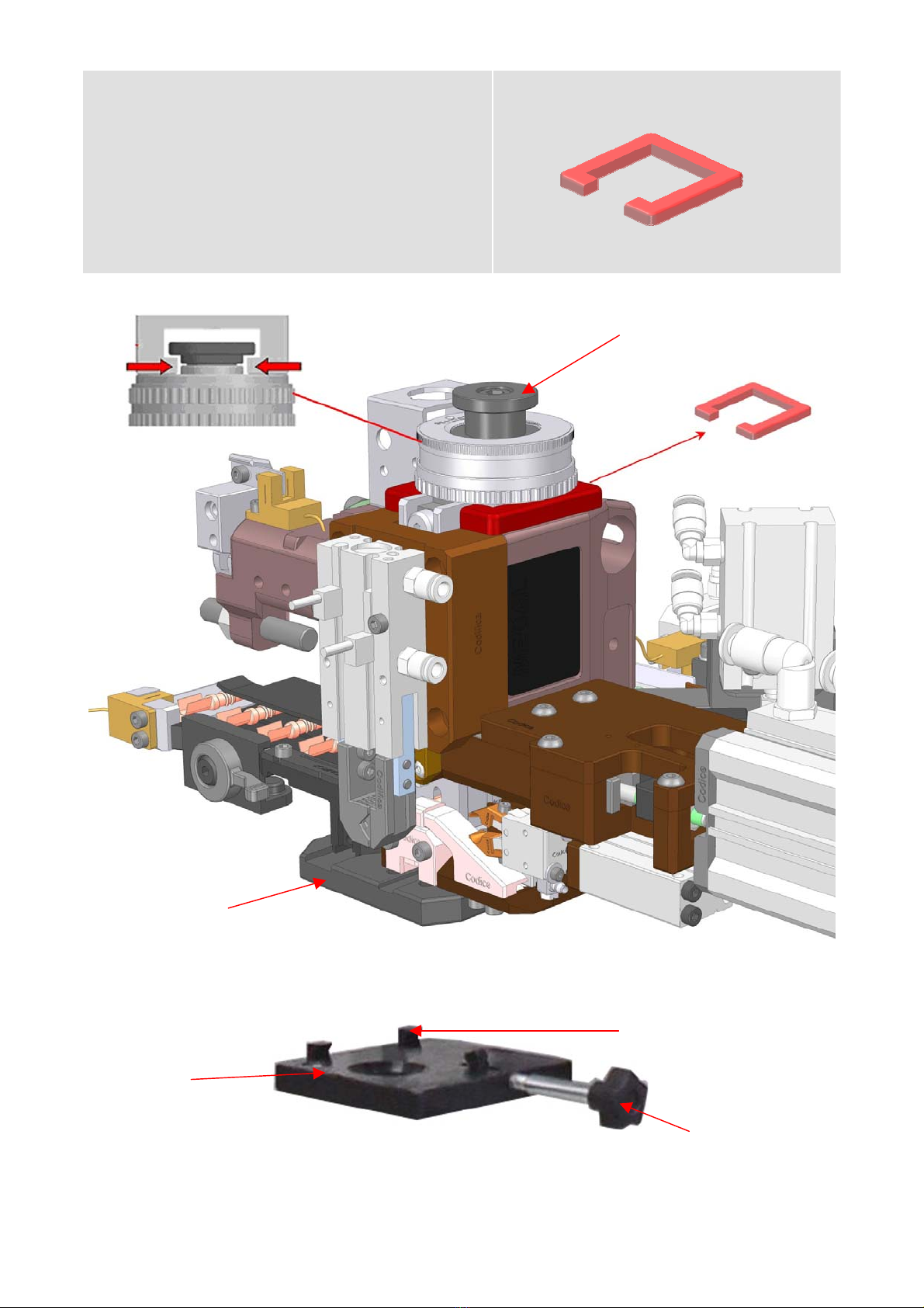
5.1) Installazione Miniapplicatore 5.1) Miniapplicator Installation
ATTENZIONE: tutte le operazioni di installazione vanno effettuate con pressa in emergenza o
spenta.
ATTENZIONE: make sure to turn off the press before performing the following steps.
• I miniapplicatori sono imballati con protezione in
gomma ( posta tra la ghiera di regolazione e il
corpo del miniapplicatore) per evitare il
danneggiamento dei particolari di aggraffatura e
taglio. Rimuovere la protezione al momento
dell’installazione.
• Posizionare l’attrezzo sulla base di fissaggio A,
allineare la basetta Ddel Miniapplicatore con il
dentino Be avvitare il pomello di serraggio C
• Verificare che la chiusura avvenga in modo
corretta controllando che l’attrezzo sia
perfettamente aderente alla base di fissaggio A. Il
perno Edell’applicatore deve essere centrato con
l’attacco a “T” della pressa.
Protezione in gomma da rimuovere
P.M.I.
Miniapplicator Operating instructions Created by Mecal s.r.l.
13
• Mecal Miniapplicator are delivered with the rubber
spacer inserted between the continuos adjusting
head and the body, to protect its during
transportation. Remove the rubber spacer when
installing the applicator.
• Place the tool on the fixing plate A, line up the
Magnum’s Dbase with the B hook and tighten up
the knob C.
• Verify that the tool is flat on the A base and make
shure that the applicator’s E pin must be perfectly
centered with referenche to the press “T “ shank.
Remove the rubber spacer
D
E
A B
C

Miniapplicator Operating instructions Created by Mecal s.r.l.
14
5.2 ) Collegamento Pneumatico ed
elettrico 5.2) Pneumatic and elettrical connection
ATTENZIONE: Per evitare collisioni, prima di collegare tutte le parti pneumatiche, verificare
che non ci siano impedimenti meccanici su tutti i sitemi in movimento.
CAUTION: To avoid collisions, before connecting all pneumatic components, make sure there
are no mechanical obstructions on all sitemi moving.
Collegare il connettore elettrico volante, presente
sulla pressa, con il connettore a pannello
posizionato sul miniapplicatore. Assicurarsi che la
ghiera di bloccaggio sia inserita e serrata.
Connect the electrical connector steering wheel,
present on the press, with the connector panel
positioned on miniapplicator. Make sure that the
locking ring is inserted and tightened.
Collegare i connettori pneumatici volanti, presenti
sul miniapplicatore, con i connettori pneumatici a
pannello presenti sulla scatola elettro / pneumatica
posizionata a lato della pressa. Assicurarsi che le
ghiere di bloccaggio siano inserite e serrate.
Connect the pneumatic connectors flying on
miniapplicator, with pneumatic connectors panel on
the external electro / pneumatic located on the side
of the press. Make sure the locking rings are
inserted and tightened.
ATTENZIONE: tutte le operazioni di collegamento connettori vanno effettuate con pressa in emergenza
o spenta e senza aria nell’impianto.
ATTENZION: all connection operations must be carried out connectors with press in emergencies or off
and no air in the system.

Miniapplicator Operating instructions Created by Mecal s.r.l.
15
5.3) Schema pneumatico 5.3) Pneumatic drawing
Miniapplicator Operating instructions Created by Mecal s.r.l.
16
5.4) Inserimento terminale 5.4) Terminal insertion
Regolare le ghiere del miniapplicatore nella posizione
corrispondente alla sezione maggiore.
Whit reference to the identification plate, position the
continous adjusting head according to the settings
related to the max wire cross section allowed.
Il miniapplicatore DEVE già essere collegato
pneumaticamente ed elettricamente e nel
sistema ci deve essere aria con pressione circa
6 BAR (vedi 5.2). Inseri.re il terminale da
aggraffare nella guida Adopo aver liberato la
frizione mediante la leva ad eccentrico B. Spingere
il terminale fino alla posizione di aggancio con il
dentino arpione Ce chiudere la frizione.
Free the cluch by means of the lever B, place the
terminal in the guide A, push it until it will be hooked
by the pawl Cand then tighten the cluch by means
of the lever B
A
B C

Miniapplicator Operating instructions Created by Mecal s.r.l.
17
Si consiglia di effettuare manualmente un ciclo completo della pressa con l’apposita
chiave e verificare che:
1) Non ci devono essere impedimenti meccanici nelle parti di scorrimento
2) Il terminale deve essere posizionato correttamente in asse con i particolari di
crimpatura e taglio. Se così non fosse consultare i paragrafi successivi 5.3
(regolazione passo) e 5.4 (regolazione terminale)
After having installed the applicator, by means of the supplied wrench manually cycle
the press, in order to check that:
1) The Magnum applicator cycles smoothly without sticking
2) The terminals correctely placed on the anvil, in line with the same and the
other crimping and cutting parts. If further adjustments are needed, please
refer to the following paragraph 5.3 (feeding adjustment) and 5.4 (terminal
regulation).
Se durante il ciclo manuale si riscontrano impedimenti meccanici verificare:
1) Corretto bloccaggio dell’applicatore sulla pressa, paragrafo 5.1 (Installazione
Magnum)
2) Corretto settaggio della pressa al P.M.I. di 135.8mm paragrafo 1 (avvertenze
importanti) e 5 (Installazione)
3) Verificare la posizione delle ghiere che non siamo completamente aperte/chiuse
(vedi 5.4)
Se il terminale non è posizionato correttamente:
1) Verificare che il dentino arpione sia nella posizione corretta di aggancio (fori su
bandella per i laterali, alette rame/resina per i frontali o altro, vedi 5.4)
2) Verificare che l’eccentrico frizione o la leva siano in posizione di lavoro (vedi 5.4)
If, while manually cycling the press, something binds, stop immediately and make sure that:
1) The tool is correctely mated to the press – see point 5.1.
2) The press id correctely set at the standard di 135.8mm crimping height – see point 1
& 5
3) The adjusting rings are not set too low (too small crimping height) – see point 5.4
If the terminal is not correctely positioned, verify that:
1) The feeding finger connects correctely with the terminal (strip holes on side-feed
appllicators, or insulation barrels on end-feed applicators) – see point 5.4
2) The brake cam and/or lever are in the operating position – see point 5.4
Effettuare una campionatura della sezione del
cavo da utilizzare avendo predisposto la ghiera
“Rame D” come indicato dai valori della
targhetta Gposta sul corpo dell’applicatore. Se
l’altezza di aggraffatura rilevata non
corrisponde a tali riferimenti controllare la
taratura della pressa al P.M.I. che deve essere
di 135.8mm (vedere paragrafo 1 avvertenze
importanti e 5 Installazione)
Set the top adjusting ring D according to the
values on the identification plate G and, using
wire of the correct section, make some
crimpings. Should the obtained crimping height
vary from the data on the identification plate,
please check the press set up according to
paragraph 1 & 5.
G
D
Miniapplicator Operating instructions Created by Mecal s.r.l.
18
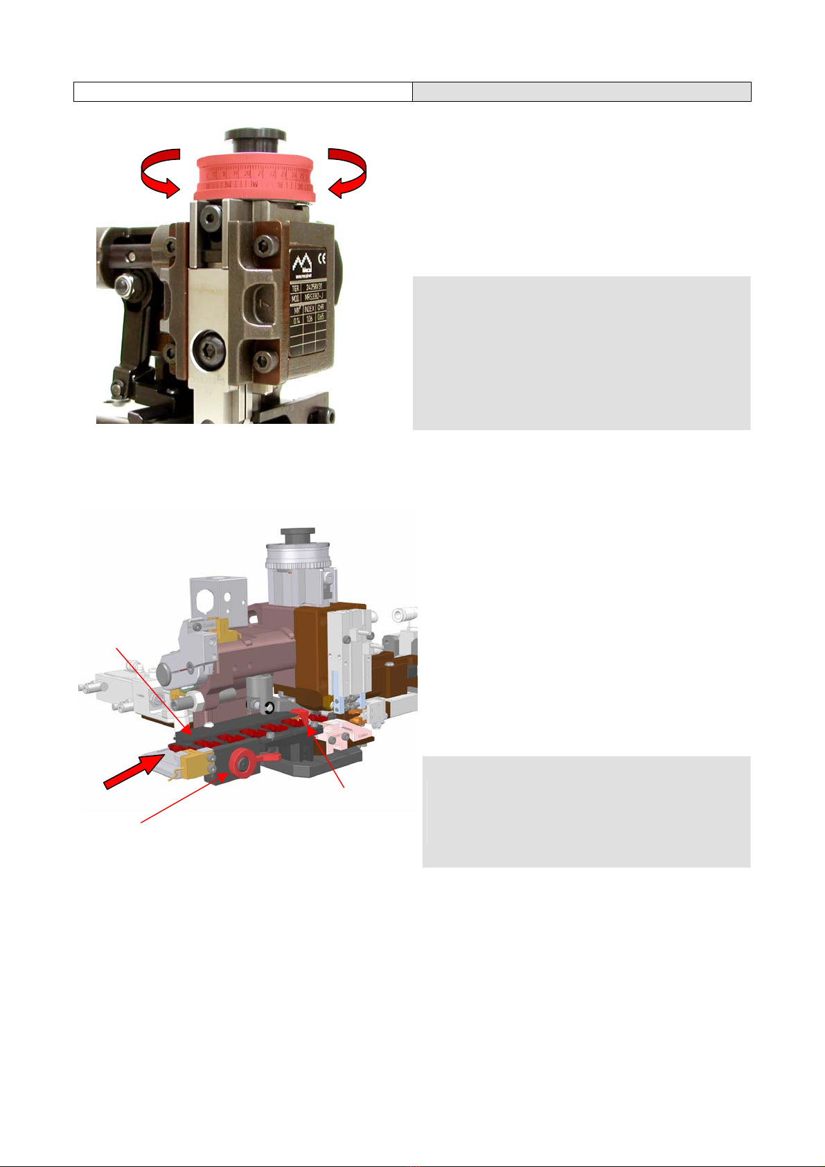
6) Regolazioni 6) Adjustments
6.1) Regolazione ghiera 6.1) Continuos adjusting head
Sulla targhetta D dell’applicatore sono riportati le sezioni del cavo da utilizzare (mm² o AWG), i valori delle
posizioni della ghiera rame (INDEX) e i valori dell’altezza di aggraffatura (CHR espressa in mm)
Regolazione altezza di aggraffatura del conduttore (ghiera A)
Al fine di impostare correttamente la ghiera per ottenere i valori di aggraffatura dichiarati sul Techical Data
Sheet e sulla targhetta, procedere come indicato nell’esempio seguente:
Esempio applicativo: Sez. cavo RTK031 INDEX=1,62 CHR=4.30
Le ghiere hanno un “range” massimo di 2,7 mm quindi sulla corona circolare esterna troviamo la siglatura da
0 a 27 con una risoluzione di 0.01mm ogni scatto. Per impostare il valore INDEX=1.62 ruotare la ghiera A
fino a raggiungere il numero inciso piu’ vicino a quello richiesto, avvicinandosi al campo di lavoro,
nell’esempio specifico il valore è 16. Tenendo conto che ogni scatto equivale a 0.01mm occorrerà
incrementare ancora di 2 scatti per ottenere il valore indicato sulla targhetta. Il valore INDEX è indicativo
perché, in funzione del tipo di pressa utilizzata e delle diverse flessioni dovute al carico di lavoro, si possono
avere dei valori che discostano leggermente da quelli indicati; è possibile un’ulteriore regolazione sulla
ghiera A per ottenere il risultato finale dell’altezza di lavoro CHR=4.30mm
Regolazione altezza di aggraffatura isolante (ghiera B)
La targhetta dell’applicatore non riporta alcun dato di aggraffatura dell’isolante. Nel caso in cui il cliente
fornisca dei parametri di aggraffatura, questi sono indicati sul Technical Data Sheet e l’ottenimento degli
stessi è garantito mediante la ghiera Bcon un processo di regolazione identico a quello descritto
precedentemente per la ghiera A. Nel caso in cui non siano state fornite specifiche di aggraffatura, Mecal
suggerisce di impostare la ghiera Bsulla posizione 0 incrementandone il valore fino a raggiungere il risultato
voluto.
A
B
C
D

Miniapplicator Operating instructions Created by Mecal s.r.l.
19
Indice di regolazione C
Per entrambe le ghiere l’indice di riferimento per la regolazione è rappresentato con una linea sul tassello di
battuta C
On the data plate D are listed the different wire sections to be used (mm² or AWG), the different positions of
the wire adjusting ring (INDEX) and the corresponding crimping height (CHR) in mm.
How to adjust the wire crimping height (A adjusting ring)
As an example, let us set up the tool along the following configuration, written on the applicator’s data plate :
Sez. RTK031 INDEX=1.62 CHR=4.30 - which means that to obtain a crimping height of mm 4.30 with a
RTK031 the adjusting ring must be set at 1.62.The A adjusting rings have a range of mm 2,7 with a
resolution of mm 0.01 (every step - represented by the numbers etched on its edge - moves the crimpers
mm 0.01 up or down). Since we’re aiming at 1.62, we have to set the adjusting ring at the closest number to
1.62, which is 16 – equivalent to an INDEX value of 16. As we want 1.62, we have to turn the adjusting ring
three more steps (0.01 + 0,01 = 0.02) to get our target (1.60 + 0.02 = 0.85). A crimping can now be done and
carefully measured : depending on the measurement obtained, turn the adjusting ring either clockwise (for
more pressure smaller crimping height) or counter-clockwise (for less pressure bigger crimping height)
until satisfied.
NOTE : this final fine adjustement is needed because the press you’re using is different from the one that
has been used to test & adjust the applicator, and since every press flexes in a different way, the applicator
has to be finely adjusted – to get the same crimping height - every time it is mounted on a different press.
How to adjust the insulation crimping height (B adjusting ring)
To set the correct insulation crimping height, follow the same procedure described above for the wire
crimping height. If no data are available regarding the insulation crimping height, set the B adjusting ring to
“0” and turn it clockwise until the resulting crimping is deemed correct.
Reference “C”
Both A and B adjusting ring must be set with reference to the C mark.
ATTENZIONE: l’esempio di “regolazione ghiera” riportato è riferito alla ghiera con risoluzione
di 0.01mm. Per gli altri modelli di ghiera commercializzati da MECAL il principio di regolazione
è lo stesso tenendo conto che la risoluzione è di 0.02 e di 0.03mm
ATTENTION: the example of "Continuos adjusting head" refers to ring back with a resolution
of 0.01mm. For other models of ring MECAL marketed by the principle of adjustment is the
same taking into account that the resolution is 0.02 and 0.03mm
I dati rilasciati e dichiarati sul Technical Data Sheet sono stati rilevati in laboratorio di collaudo
con pressa Mecal P107C tarata ad un’altezza di lavoro (P.M.I.) di 135,8mm
The data as per our Technical Data Sheet have been collected using a Mecal P107C press
set at di 135,8mm shut height (Bottom Dead Center).
La regolazione delle ghiere è valevole per tutti i modelli di miniapplicatori. Nel caso in cui il
modello fosse equipaggiato con ghiere di regolazione a tacche sulla targhetta saranno
riportate le lettere da A a D (come incise sulla ghiera stessa) con relativa altezza di lavoro.
Regulation of rings is valid for all models of mini applicators. In the case where the model
was fitted with seals adjustment notches on the plate are given the letters A to D (as
engraved on the ring itself) with its height of work.
Miniapplicator Operating instructions Created by Mecal s.r.l.
20
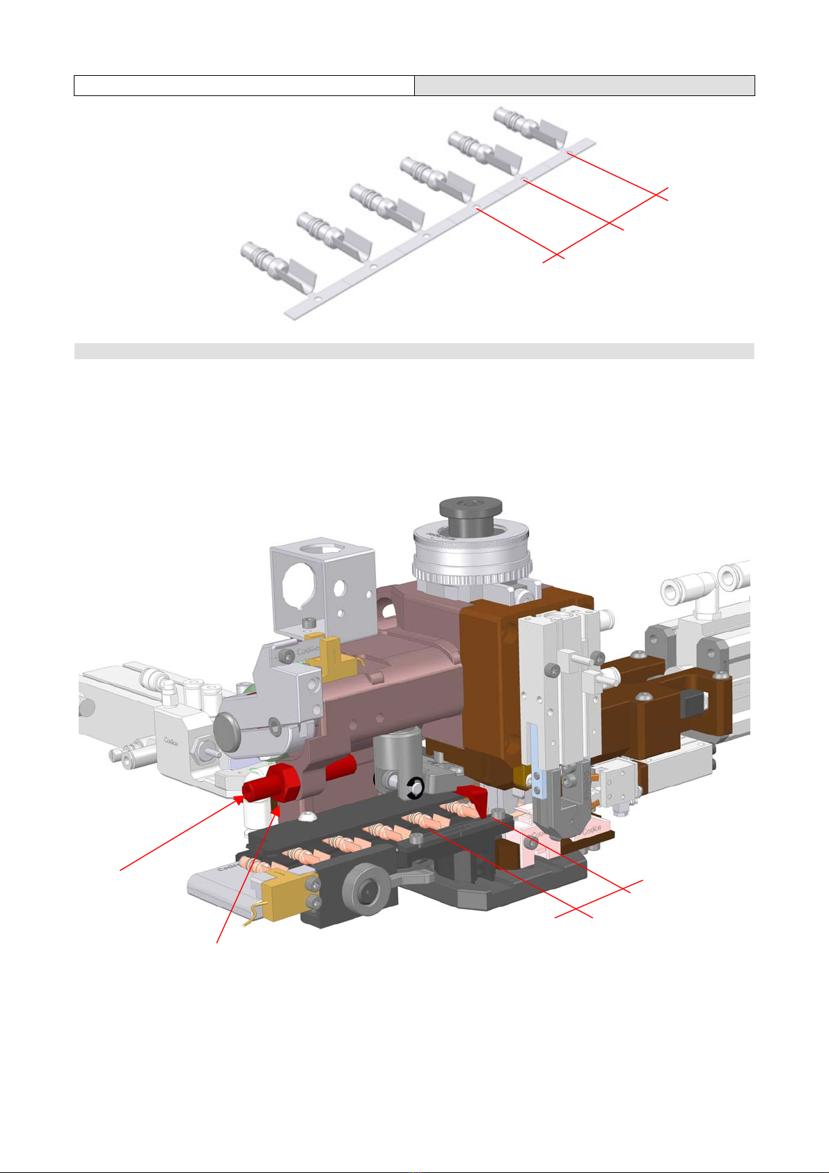
6.2) Regolazione passo terminale 6.2) Feeding adjustment
Il passo pè dato dalla distanza che intercorre tra un terminale e quello successivo.
The terminal pitch pis the distance between a terminal and the next one.
La regolazione del passo psul miniapplicatore serve per poter agganciare il terminale e portarlo in posizione
di aggraffatura durante ogni ciclo di lavoro. Allentare il dado Aed intervenire sul grano di regolazione Bcon
chiave esagonale CH4. Ruotando il grano Bin senso orario si riduce il passo del terminale, in senso
antiorario si aumenta. Terminata la regolazione serrare il dado di bloccaggio A. La velocità d’avanzamento si
puo’ controllare intervenendo sul regolatore di flusso dell’aria C.
p
p
A
p
B
Table of contents
Other Mecal Industrial Equipment manuals


