Medema MC 1122 Quantum User manual

Service Manual
MC 1122 Quantum
P9-0222-S ver. 1.0.0 - August 2013 GB
medemagroup

Service Manual P9-0222-S 2 of 70 Version 1.0.0/2013
Medema Production A/S

Service Manual P9-0222-S 3 of 70 Version 1.0.0/2013
Medema Production A/S
Content
Introduction............................................................................ 5
Symbols.................................................................................. 6
Warning! ................................................................................. 6
Safe servicing ........................................................................ 7
Tool list ................................................................................... 8
Introduction DX2.................................................................... 9
Joystick parts ........................................................................ 9
Operating................................................................................ 9
Error Code.............................................................................. 16
Extra........................................................................................ 18
Replacing Joystick................................................................ 20
Troubleshooting .................................................................... 22
Programming ......................................................................... 24
Maintenance........................................................................... 25
Servicing the MC Concept 1122 - Concept Chair ............... 27
Checking the rear bar............................................................ 28
Suspension replacement ..................................................... 29
Checking/replacing the caster-/anti-tip wheel .................... 31
Changing the central wheel.................................................. 35
Checking the disengagement............................................... 39
Checking the brakes ............................................................. 40
Replacing the motor gear ..................................................... 41
Seat replacement................................................................... 47
Actuator module replacement ............................................. 49
Lift/tilt disassembly .............................................................. 50
Cover disassembly ............................................................... 51
Controler replacement ......................................................... 52
Fender wheel installation ..................................................... 53
Lamp installation................................................................... 55
Power plate plugs.................................................................. 57
Checking the bolts ................................................................ 58
Fuses ...................................................................................... 59
Changing the battery............................................................. 60
Checking the battery poles and strap ................................. 63
Dynamic DX2.......................................................................... 64
Motor, control - Dynamic ...................................................... 64
Technical data........................................................................ 65
Wiring diagram ...................................................................... 68

Service Manual P9-0222-S 4 of 70 Version 1.0.0/2013
Medema Production A/S

Service Manual P9-0222-S 5 of 70 Version 1.0.0/2013
Medema Production A/S
Introduction
This manual contains servicing instructions for the MC Concept
1122.
The Service Manual is a supplement to our Spare Parts
Catalogue and User Manual.
MC Concept 1122 is designed for safe travel for at least 10
years, up to a max. of 5,000 hours, provided it is serviced and
safety-checked every year, corresponding to 500 hours of
operation. The service must be carried out by an authorised
workshop.
IMPORTANT! For safety reasons it is of the utmost importance
that the servicing and safety check intervals are complied with,
as this minimises the risk of brake failure and short-circuits in
the wiring, which could generate heat and cause a re.
If help is required with troubleshooting, Medema Production A/S
is always happy to provide telephone assistance. If the problem
seems to be an electrical fault that prevents the MC Concept
1122 from working, please tell us the error code. This can be
found on the battery indicator on the control panel. Read more
about this in the section on Troubleshooting.
Please also have the MC Concept 1122 serial number handy
when contacting Medema Production A/S.
If you have any questions that are not answered directly by this
manual, you are always welcome to contact us at:
Medema Production A/S
Tel: +45 7010 2054
Email: info@minicrosser.com
Internet: www.minicrosser.com
NB: Errors and omissions excepted. Specications subject to
change.
Medema Production also reserves the right to update the
service manual in line with any modications or improvements
to the product.

Service Manual P9-0222-S 6 of 70 Version 1.0.0/2013
Medema Production A/S
Symbols
sed in the manual to indicate sections describing situations
where extra care is required owing to the risk of personal injury.
Used to indicate sections on electromagnetic compatibility
(EMC).
Warning!
For safety reasons the vehicle must not be lent to persons who
are not completely familiar with it. The vehicle is designed for
one person only.
The MC Concept 1122 has been designed for users weighing
max. 150 kg.
Joystick
The joystick control box should not be exposed to extreme
temperatures or be in a humid environment for a long time.
The joystick control box must not be exposed to severe stroke.
Do not turn of the control box while driving, except in
emergencies, since this can damage the electronics.
For cleaning use a damp cloth with a mild soapy solution.
Do not let water or moisture into the steering box.
Seat and backrest
The upholstery fabrics on the seat and backrest can be washed
in a washing machine. Washing instructions are on the back of
the seat pad / backrest.

Service Manual P9-0222-S 7 of 70 Version 1.0.0/2013
Medema Production A/S
Safe servicing
To avoid injuries to both the service engineer and the
subsequent user of the MC Concept, it is important to get to
know the product before servicing it.
Be particularly aware of the following:
The MC Concept MUST be turned off at the main switch. If
electrical components are being serviced, the positive terminal on
the battery MUST also be disconnected.
If the voltage needs to be measured in the course of
troubleshooting, take great care not to short-circuit anything.
Take great care not to short-circuit the battery terminals.
Be careful not to lift heavy parts such as the seat, battery and
motor gear incorrectly or drop them.
Make sure to raise one rear wheel off the ground so that the MC
Concept cannot drive off accidentally.
Use professionally maintained tools.
Where lock nuts are used, NEW ones MUST be tted when the
MC Concept is reassembled.
Take care to t new cable strips in the same way as the old ones.
Make sure that no cables can be trapped by moving parts or stick
out in such a way as to catch on things.
End every service by making sure that the product is roadworthy:
- Check that all the connectors are plugged in correctly.
- Check that all the mechanical parts are properly secured.

Service Manual P9-0222-S 8 of 70 Version 1.0.0/2013
Medema Production A/S
Tool list
The following tools are needed to service the MC Concepten:
Circlip pliers
Allen keys
Allen 9/64
Box spanners, 7-17 mm
Open-ended spanners, 7-17 mm
Phillips and torx screwdrivers, 10/15/20/25 kærv.
Needle-nose pliers
Side-cutting pliers
Plastic hammer
Set of punches
Retractable knife
Steel brush
Water pump pliers
Wire strippers
Crimping tool
Pliers for Molex 5556/5558 crimps
Riveting pliers
Small cable ties
Multimeter
Battery tester
Tyre pressure gauge
Tyre pump with Schrader valve
Acid-free oil and grease
Loctite 406 / 603
Cable ties
Cable tie bar
Circlip Pliers

Service Manual P9-0222-S 9 of 70 Version 1.0.0/2013
Medema Production A/S
1
3
5
4
7
8
2
6
Introduction DX2
DX2 is the rst in a new generation of joysticks to control the
electric wheelchair. With its large color LCD screen and its
logical icon built menu structure, it directs the user to the target.
Joystick parts
Dynamic DX2 AJR
1 Start/stop button
2 Indicator left
3 Indicator right
4 Select
5 Display
6 Speed selector
7 Accessory Selector
8 Horn
Operating
At the top of the display you will nd the status bar. Battery indicator
is displayed constantly. The clock can be turned on or off as you
wish. The other is lit when the corresponding function is active.
1 Battery indicator
Green = fully charged
Yellow = least half full
Red = almost empty - charge now!
2 Indicator left is active
When hazard warning lights are active, both icons blinks.
3 Lights on
4 Error code - see section on error codes.
5 Indicator right is active
When hazard warning lights are active, both icons blinks.
6 Real time
1 2 3 4 5 6

Service Manual P9-0222-S 10 of 70 Version 1.0.0/2013
Medema Production A/S
Clock on/off
Press arrow up/down or joystick (push forward) until the above
icon is showed in the center of the screen.
Use ”Select” to switch between X and .
Accept by pressing the arrow up/down button.

Service Manual P9-0222-S 11 of 70 Version 1.0.0/2013
Medema Production A/S
Set Speed
When you turn the joystick on, the image shown below will be
presented in the display. The number in the centre shows the
speed you have chosen as max speed. Change the Speed by
selecting the plus / minus key. Maximum speed is 5, lowest is 1.
Find the features in the bottom with the “Select” button.
Chosen speed
Select
Chosen speed
Press the arrow up / down until the image shows the chair. Use
the “Select” to choose the function you want modied. Use the
joystick to change example angle of the seat back.
Setting the seat - back and leg supports
Select

Service Manual P9-0222-S 12 of 70 Version 1.0.0/2013
Medema Production A/S
Function Icon
Seat angle (Tilt)
Backrest angle
Seat height
Left footrest
Right footrest
footrest both
Only the available options will be displayed.

Service Manual P9-0222-S 13 of 70 Version 1.0.0/2013
Medema Production A/S
Light on / off
Push the arrow up / down until the image for light is shown in
the centre.
Push the joystick forward to turn the light on. And again to turn
of the light.
Push the joystick back to activate the hazard warning lights.
Push the joystick back again to turn it of.
Push the joystick right or left to activate the indicators right or
left. Turn of the indicators by puching the joystick to the same
side again.
Press the arrow up / down until the sun i shown i the centre.
Push the joystick forward to enter the settings. Use the Select
button or joystick right / left to change the brightness.
Use Joystick forward / back or arrow up / down to accept the
new settings and return to the main menu.
Setting the Backlight

Service Manual P9-0222-S 14 of 70 Version 1.0.0/2013
Medema Production A/S
Setting the display environment
Use the arrows up /down until “day / night” icon i shown in the
centre. Push the joystick forward to enter settings. The image
below will show.
1 2 3
Setting Result
1 - Indoor The display will show a black background color.
2 - Outdoor The display will show a white background color.
3 - Automatic The background color will change (black/white) accordingly to
the surrounding light.
Use ”Select” or joystick right / left to select setting.
Push the joystick forward to accept the new settings and return
to the main menu.
If you push the Joystick back or use the arrow up / down, the
new setting will be dismissed and you will return to the main
menu.
Exit / Cancel
Exit / Cancel

Service Manual P9-0222-S 15 of 70 Version 1.0.0/2013
Medema Production A/S
Setting the Clock
Use arrow up / down until the clock is shown in the centre. Push
the joystick forward to enter settings. The image below will show.
Press the Select button or push the joystick right / left to choose
the digit to change.
Joystick forward make the number count forward.
Joystick back accept the new settings and return to the main
menu.
Arrow up / down dismiss the new settings and return to the
main menu.
System lock
To lock the DX system
Press the on / off button, for 4 sec. while the system is turned on.
The system will now shut down in locked condition.

Service Manual P9-0222-S 16 of 70 Version 1.0.0/2013
Medema Production A/S
Error Code
Code Cause Meaning
1 DX Module Could mean:
- Errors in programming
- Error in wire connection
- Internal fault in a module
Turn off the chair and turn on again. If it doesn’t works,
contact qualied technician (HMC or therapist).
2DX Accessory Could mean:
- driving slowly because of raised seat.
(programming). Not an arror.
Lower the seat as much as possible. If it doesn’t works,
contact qualied technician (HMC or therapist).
3 Motor 1 / L
(M1)
Could mean:
- Loose connection from the engine to power module
- Short circuit
Check that no plug is loose.
Contact competent technician (HMC or therapist).
4 Motor 2 / L
(M2)
Could mean:
- Loose connection from the engine to power module
- Short circuit
Check that no plug is loose.
Contact competent technician (HMC or therapist).
5 Parking brake
1 (M1 left)
Could mean:
- Loose connection
- Short circuit
Check that no plug is loose.
Contact competent technician (HMC or therapist).
6 Parking brake
2 (M2 right)
Could mean:
- Loose connection
- Short circuit
Check that no plug is loose.
Contact competent technician (HMC or therapist).
To unlock the DX system
Press the on / off button. The system will show a lock in the display.
Press the horn twice within 10 seconds. The system will boot
normally.

Service Manual P9-0222-S 17 of 70 Version 1.0.0/2013
Medema Production A/S
Code Cause Meaning
7 Low battery
voltage
Can mean:
- the battery or charger is faulty. Has signicance for the
chair’s safety. The chair stops.
8 High battery
voltage
Can mean:
- that it has regenerated more than normal (over 32V),
perhaps from descending a steep hill. Has signicance
for the chair’s safety. The chair stops. Check that the
battery cables and connectors are secure.
9 Wiring Errors Can mean:
- that there is a fault on the BUS cable.
10 Wiring Errors Can mean:
- that there is a fault on the BUS cable.
11 Stall timeout
error
Can mean:
- the chair will stop, if you continue to try to get through/
over an obstacle when it is not possible. Be sure that
the motors are free and can run. Turn the chair off and
on.
12 Faulty module
coupling
Can mean:
- that there is a software/module incompatibility.
Reprogram or contact a competent technician.
Errors effecting the chair’s safety will cause the chair to stop,
while less critical faults will be indicated, but will allow continuous
chair operation.
Some errors will automatically disappear when the cause of
error is removed. In such cases, the diode will stop ashing, and
the chair can be operated normally. Others should be deleted
(latched). You press the button until the error light disappears.
Wait 2 seconds and it will work optimally again.
The “Left” and “Right” condition refers to the motor’s parking
brake when the motor alignment is set to ”no”. The motor outlet is
marked M1 and M2.
8 GBK52983 iPortal2 User Manual iPortal
4. iPortal
DYNAMIC CONTROLS’iPortal is a bridge between your powered-wheelchair and your
communications technology.
When combined with an iOS device and the Dashboard
application, iPortal provides the powered-wheelchair user
with essential wheelchair information such as battery state,
driving speed, seating adjustments, and an emergency call
function.
When combined with an iOS device and the Accessibility feature, the powered-
wheelchair‟s remote joystick is used to navigate and interact with your iOS device.
When combined with a PC or laptop and the Mouse Mover feature, the wheelchair‟s
joystick or other speciality input device is used to navigate and interact with your PC
or laptop‟s mouse pointer.
Service Manual P9-0222-S 18 of 70 Version 1.0.0/2013
Medema Production A/S
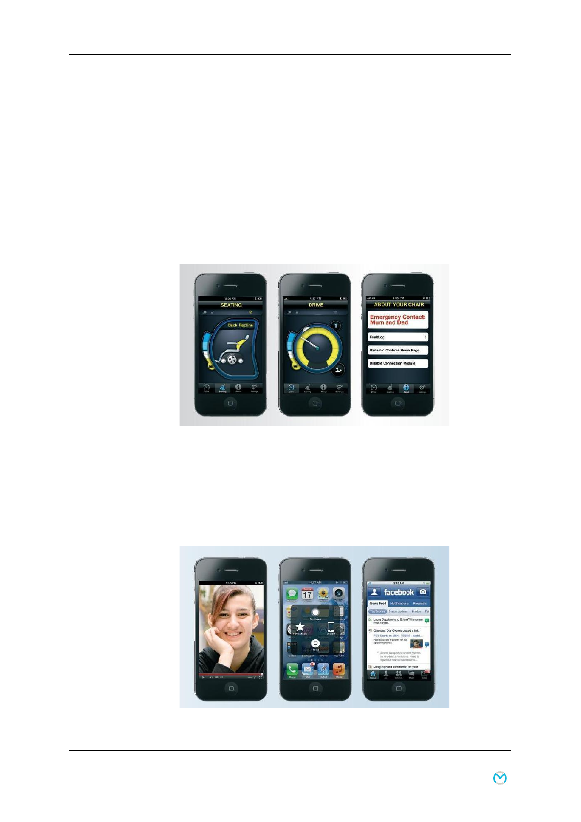
Extra
With Dynamic Controls’ iPortal a bridge is created between the
joystick and iPhone/iPod touch or iPad.
Option 1: iPortal Dashboard, a free app you can download
from the iPortal store via iTunes. When combined with an
IOS module, it makes it possible to view essential wheelchair
information, such as the batteries’ charge level, seat settings
and the emergency dialing function. (The emergency dialing
function only applies in combination with an iPhone).
iPhone/iPad touch and iPad connect to the wheelchair via
Bluetooth.
Option 2: Accessibility. With the purchase of the package with
Accessibility, you can control your iPhone/iPad touch or iPad
with the joystick.

8 GBK52983 iPortal2 User Manual iPortal
4. iPortal
DYNAMIC CONTROLS’iPortal is a bridge between your powered-wheelchair and your
communications technology.
When combined with an iOS device and the Dashboard
application, iPortal provides the powered-wheelchair user
with essential wheelchair information such as battery state,
driving speed, seating adjustments, and an emergency call
function.
When combined with an iOS device and the Accessibility feature, the powered-
wheelchair‟s remote joystick is used to navigate and interact with your iOS device.
When combined with a PC or laptop and the Mouse Mover feature, the wheelchair‟s
joystick or other speciality input device is used to navigate and interact with your PC
or laptop‟s mouse pointer.
Service Manual P9-0222-S 19 of 70 Version 1.0.0/2013
Medema Production A/S
Option 4: Mouse Mover + Accessibility. This package with both
Accessibility and Mouse Mover has it all.
Information on installation and use are shown in a separate
guide, included with the purchase.
Option 3: Mouse Mover – with iPortal Mouse Mover you are
able to control your pc/mac/tablet mouse with the joystick.
Overview of iPortal2 packages
iPortal2 art. No Description
DJ-BTINT iPortal Dashboard
DJ-BTINT-ACC iPortal Accessibility
DJ-BTINT-HID iPortal Mouse Mover
DJ-BTINT-HID-ACC iPortal Mouse Mover + Accessibility

Service Manual P9-0222-S 20 of 70 Version 1.0.0/2013
Medema Production A/S
Replacing Joystick
Remove the plastic strip that keeps the cord to the joystick.
Unscrew the cover. Unplug the joystick. Note that there
is a lock on.
Press the latch and pull the plug.
Table of contents
Other Medema Scooter manuals

Medema
Medema Mini Crosser M1 Cabin User manual

Medema
Medema Mini Crosses M2 4W Cabin User manual

Medema
Medema Mini Crosser M1 User manual

Medema
Medema Mini Crosser M1 User manual

Medema
Medema Mini Crosser M2 User manual

Medema
Medema Mobility Scooter User manual

Medema
Medema Mini Crosser X1 User manual

Medema
Medema Mini Crosser M-MaxX User manual

Medema
Medema M Joy User manual

Medema
Medema M1 joy User manual
Popular Scooter manuals by other brands


Insportline
Insportline Billar IN 20041 user manual

Derbi
Derbi BOULEVARD 50 2T Workshop manual

Pride Mobility
Pride Mobility The Ultimate In Style & Performance owner's manual

Esperia
Esperia Xenon E960 user manual

Shoprider
Shoprider eclipse 778EL instruction manual

Vermeiren
Vermeiren venus 3 t3g user manual