Medisoft Ergocard CPX Instructions for use
Version 2.2
30/12/2019
H4-EN
HARDWARE USER MANUAL
Ergocar CPX

H4-EN Ergocard CPX P
AGE
2/44
Content
1
Forewor .................................................................................................................. 5
1.1
Foreword ..................................................................................................................... 5
1.2
Description o available tests ...................................................................................... 6
1.3
List o standard and optional tests .............................................................................. 7
1.4
Intended users ............................................................................................................. 8
1.5
Environmental conditions............................................................................................ 8
1.6
Accessories, additional equipment and gas cylinders ................................................. 9
1.6.1
Standard accessories .................................................................................................................... 9
1.6.2
Single use accessories ................................................................................................................... 9
1.6.3
Additional equipment ................................................................................................................. 10
1.6.4
Gas cylinder ................................................................................................................................. 12
2
Warnings ................................................................................................................. 13
2.1
Location o the device ............................................................................................... 13
2.2
Gas cylinders .............................................................................................................. 14
2.3
Displacement o the device ....................................................................................... 15
3
General overview .................................................................................................... 16
3.1
CPET system ............................................................................................................... 16
3.2
Front panel................................................................................................................. 17
3.3
Rear panel .................................................................................................................. 18
4
Connections ............................................................................................................ 19
4.1
Connections on ront panel ....................................................................................... 19
4.2
Rear panel connections ............................................................................................. 20
5
Calibration .............................................................................................................. 21
5.1
Foreword ................................................................................................................... 21
5.2
Preparing the equipment .......................................................................................... 22
5.3
Initializing the calibration mode ................................................................................ 23
5.4
Volume calibration .................................................................................................... 25
5.4.1
Calibrating the Prevent Pitot tube .............................................................................................. 25
5.4.2
Checking the Prevent low sensor calibration ............................................................................ 30
5.5
Gas calibration ........................................................................................................... 32
5.5.1
O2-CO2 gas calibration ............................................................................................................... 32
5.5.2
He/CH4-CO gas calibration ......................................................................................................... 37
6
Maintenance ........................................................................................................... 41
6.1
Forward ...................................................................................................................... 41

H4-EN Ergocard CPX P
AGE
3/44
6.2
Maintenance planning ............................................................................................... 42
6.2.1
Maintenance planning or Ergocard CPX Clinical ........................................................................ 42
6.2.2
Maintenance planning or Ergocard CPX Pro essional ................................................................ 43

H4-EN Ergocard CPX P
AGE
4/44
Revision
Date
Version
Mo ifications
22/12/2017
1
.0
Creation
01/06/2018
2.0
New design
14/05/2019
2.1
Modi ication o the CE marking
30/12/2019
2.2
Removing dedundant
in ormation’s

H4-EN Foreword P
AGE
5/44
1
1Forewor
1.1 Forewor
The Ergocard CPX is a medical device manu actured by Mediso t S.A. which allows cardio-
pulmonary exercise testing (CPET) or children and adults. The Ergocard CPX is intended or
measuring gas exchange during a maximal exercise. Additionally, other options are available
to complete the cardio-pulmonary testing.
The Ergocard CPX is operated by Expair, a so tware program developed by Mediso t S.A. that
unctions on Windows based PC systems.
The Ergocard CPX is manu actured, calibrated and applied in con ormity with latest technical
requirements and o icial recommendations o the ATS and ERS. The Ergocard CPX adopts
Pitot tube technology or low/volume measurement. A ull weather station (temperature,
humidity and barometric sensor) or the correct determination o the BTPS correction actor
is included.
The Ergocard CPX device has two models available:
•Ergocard CPX Clinical
•Ergocard CPX Pro essional
The Ergocard CPX Clinical is the basic model. It uses an electrochemical cell or oxygen
measurement and a non-dispersive in rared CO
2
analyser.
The Ergocard CPX Professional model is more complete and lexible. It uses a laser
spectroscopy analyser or oxygen measurement and a non-dispersive in rared CO
2
analyser.
Options can be added to this model to complete the range o tests: lung volume
measurement, CPET under hypoxia or hyperoxia conditions, and cardiac output
measurements.
On the ollowing pages, you will ind the instructions needed to operate your instrument
e ectively or practical uses. Please read this manual care ully be ore using the equipment
or the irst time.
The content o this document is subject to periodic update and revision. Please note that
some items may be modi ied slightly in later versions o the so tware.

H4-EN Foreword P
AGE
6/44
1
1.2 Description of available tests
The Ergocard CPX device allows several types o measurement:
•Conventional spirometry
•Cardio-respiratory testing
•Lung volumes (only available or Ergocard CPX Pro essional)
•Lung di usion (only available or Ergocard CPX Pro essional)
Spirometry
The conventional spirometry includes:
•Slow spirometry with measurement o lung-volume subdivisions (VC, TV, ERV, IRV, IC,
EC)
•Forced expiratory maneuver (FEV
1
, FVC, PEF, intermediate lows, FEF25-75…)
•Maximal voluntary ventilation test (MVV)
•Tidal minute ventilation test (Vmin)
Cardio-respiratory testing
The cardiopulmonary exercise testing consists in measuring the electrocardiogram,
ventilation and gas exchange (oxygen consumption and CO
2
production) during maximal
exercise per ormed by the patient on a treadmill, bicycle, arm ergometer, etc. This test can
also be done under hypo or hyperoxia conditions.
Additional measurements that can be done during the test:
•Pulse oximetry or evaluation o the saturation level (SpO
2
)
•Non-invasive blood pressure measurement (NIBP)
•Heart rate measurement with an heart rate belt
•Cardiac output by CO
2
rebreathing (indirect Fick method)
Lung volumes
The Ergocard CPX Pro essional allows per orming static lung volumes measurement by using
the Nitrogen washout method.
This allows assessing the static lung volumes which are required or the complete
interpretation o the pulmonary unction test. Lung capacities include total lung capacity
(TLC), unctional residual capacity (FRC), vital capacity (VC), and inspiratory capacity (IC).
Lung volumes include residual volume (RV), expiratory reserve volume (ERV), tidal volume
(Vt), expiratory and inspiratory reserve volume (ERV, IRV).
N
2
washout technique also allows estimating heterogeneity o ventilation by Lung clearance
index (LCI).

H4-EN Foreword P
AGE
7/44
1
Di usion
The Ergocard CPX Pro essional allows per orming several techniques o lung di using
capacity:
•Single breath real time DLCO technique with Helium or Methane tracer gas
•Intrabreath DLCO
Test gas mixture can be delivered in two di erent ways:
•Using an inspiratory bag
•Using a demand valve
1.3 List of stan ar an optional tests
SPIROMETRY Abbreviation Stan ar /optional
Clinical Pro
Vital Capacity VC standard standard
Forced Vital Capacity FVC standard standard
Maximum voluntary ventilation MVV standard standard
Minute tidal ventilation Vmin standard standard
Reversibility (pre/post) standard standard
Challenge (only so tware) standard standard
LUNG VOLUME
Lung volumes by N
2
washout– Inspiratory Bag or Demand Valve FRC-N
2
IB/DV NA optional
Closing volumes – N
2
slope – Inspiratory Bag or Demand Valve N
2
slope IB/DV NA optional
DIFFUSION
DLCO Helium rapid - Inspiratory Bag or Demand Valve DLCO-He Fast
IB/DV NA optional
DLCO Methane - Inspiratory Bag or Demand Valve DLCO-CH
4
IB/DV NA optional
DLCO intrabreath - Inspiratory Bag or Demand Valve DLCO ib IB/DV NA optional
CARDIO-RESPIRATORY
Gas exchange VO
2
-VCO
2
breath to breath VO
2
standard standard
Ventilation e ort study VE optional optional
Hypoxia and Hyperoxia testing Hypo-Hyperoxia NA optional
SpO
2
oximetry (NONIN) SpO
2
optional standard
Non-invasive blood pressure (Tango external module) NIBP optional optional
Heart rate belt (Zephyr) HR optional optional
ECG-rest-stress 12 lead (Cardioline) ECG optional optional
Cardiac output by CO
2
rebreathing QT-CO
2
NA optional
Indirect calorimetry - nutrition Calorimetry optional optional
OTHER TESTS
Negative Expiratory Pressure NEP NA optional

H4-EN Foreword P
AGE
8/44
1
1.4 Inten e users
This device is to be used by physiologists, doctors, respiratory therapists or nurses, or under
the supervision o such. Data obtained must be interpreted and reported by trained medical
sta only.
1.5 Environmental con itions
This device is or clinical use in hospitals, private doctor’s o ices, medical schools, sports
medicine acilities or universities.
The ambient conditions must be within the speci ied range:
•Temperature: 10 to 35°C
•Humidity: 25 to 85% (non-condensed)

H4-EN Foreword P
AGE
9/44
1
1.6 Accessories, a itional equipment an gas cylin ers
1.6.1 Stan ar accessories
The table below gives the list o accessories intended to be used with the device. This device
is certi ied in con ormity with all o these accessories.
Use of accessories
The use o other accessories than those provided with the system can disrupt
the reliability and the sa ety o the unit, users or the other devices placed
nearby.
Accessory Me isoft Part
Number
Mo el
Clinical
Mo el
Professional
Power supply cable (length 2 m) 11101013
Mini USB cable (length 2 m) 11126032
3-liter calibration syringe 35180000
Light blue rubber adapter 12001155
Tube ∅4 length 3 m or connection to gas cylinder 11003042
Tube ∅8 length 3 m or connection to 100% O
2
gas cylinder 11002003
FRC-N
2
PVC Bag 9 liters 35080003
FRC-N
2
PVC bag 7 liters 35080002
QT-CO
2
PVC bag 40 liters 35080004
Hypo-
hyperoxia
Umbilical 12001154
Prevent low sensor 12001160
Silicon ace mask (extra small)
Silicon ace mask (small)
Silicon ace mask (medium)
Silicon ace mask (large)
Silicon ace mask type paediatric
12001105
12001104
12001103
12001102
12001106
Adaptator or silicon mask Prevent Pitot tube 12001156
Cap or silicon mask (small)
Cap or silicon mask (medium)
Cap or silicon mask (large)
12001107
12001108
12001109
Mouthpiece with saliva trap (medium)
Mouthpiece with saliva trap (large)
12001040
12001167
1.6.2 Single use accessories
Accessory Me isoft Part
Number
Mo el
Clinical
Mo el
Professional
PVC nose clip 12001038

H4-EN Foreword P
AGE
10/44
1
1.6.3 A itional equipment
Other accessory devices, such as computers, may be inter aced to the Ergocard device. Using
accessory equipment that does not comply with the equivalent sa ety requirements o this
equipment may lead to a reduced level o sa ety and/or per ormance o the system.
Mediso t S.A. recommends that the user/customer employ the use o a line isolation
trans ormer with all accessory devices. Any accessories inter aced with this device must be
compliant with the IEC60601-1 and IEC 60601-1-2 standard.
For in ormation about the connection o any additional equipment not listed below, please
contact Mediso t S.A. or its representative.
Printer
A printer can be used to print test results.
For ECG trace printing:
•Minimal required print speed: 15 ppm
•Recommended printer: Canon
Trolley
A trolley can be used to place the in ormatics equipment (computer, printer,...). The trolley
has to be medical grade and use an isolation trans ormer i the Ergocard is powered by the
trolley.
The positioning o the Ergocard module on a trolley not supplied by Mediso t S.A. is the
responsibility o the customer.
Computer
A computer is intended to be used with the device in order to run the Expair so tware. The
choice o the computer used is the responsibility o the customer.
Minimal required speci ications:
•Operating system: Windows 7 Pro 32/64 bits, Windows 8 Pro (8.1) 32/64 bits,
Windows 10
•CPU: minimum 3.5 GHz
•Hard disk: minimum 500 Gb
•RAM: DDR, minimum 4 Gb, minimum 1666 MHz
•1 SVGA graphics port or HDMI
•4 USB 2.0 ports minimum
•2 USB 3.0 ports minimum
•Keyboard / mouse / touch screen
Heart rate instrument
A heart rate instrument can be used to measure heart rate.
Approved device: Zephyr HXM BT (wireless Bluetooth heart rate monitor)

H4-EN Foreword P
AGE
11/44
1
ECG
An electrocardiogram can be used in combination with the Ergocard.
Approved device:
•Cardioline clickECG
•Cardioline HD+ wireless ECG
•GE CardioSo t V6.73
•Mortara XScribe CPI V4.0.1
Bloo pressure monitor
A blood pressure instrument can be used in combination with the Ergocard.
Approved device:
•Ergoline
oErgoselect 100P with blood pressure
oErgoselect 200P with blood pressure
oErgoselect 4 with blood pressure
oErgoselect 5 with blood pressure
•Suntech Medical Tango 2M
Pulse oximeter
A pulse oximeter can be used in combination with the Ergocard.
Approved device: SpO2 inger sensor NONIN 8000SM, 8000SS, 8000 SL
Bicycle
A bicycle can be used to allow to the patient per orming exercise test.
Approved bicycle:
•Ergoline
oErgoselect 100P
oErgoselect 200P
oErgoselect 4
oErgoselect 5
•Lode
oCorival
oExcalibur
Trea mill
A treadmill can be used to allow to the patient to per orm exercise test.
Approved treadmill:
•Mediso t RAM 870A, 870S, 870C
•Lode Valiant
•All treadmills with Trackmaster driver
H4-EN Foreword P
AGE
12/44
1
1.6.4 Gas cylin er
The Ergocard device needs a supply o calibration gases in order to ensure accurate gas
concentration measurements.
Please take note o the recommendations above in order to correctly choose the gas and the
gas supplier.
Gas cylin er supply
•The supply o gas cylinders and tank regulators are the responsibility o
the customer.
•The tolerance o the analyzed gas concentrations, the tank regulators,
the connection and the tightness o the tank regulators are under the
ull responsibility o the customer.
•The length o the gas lines between gas cylinders and devices must not
exceed 3 meters.
•The gas inhaled by a subject is considered a medical gas and may only
be obtained by prescription.
List of gas cylin ers
Gas tank
O
2
CO
2
N
2
Info
Nominal
fraction
Fraction
range
Nominal
fraction
Fraction
range
O
2
-CO
2
16% 15-17% 4% 3.5-5.5% Balance Gas used or the calibration o
the analysers
Ambient 21% 20-22% -- -- Balance Gas used or the zero o the
analysers ( acultative)
100% O
2
100% -- -- -- --
Gas inhaled by the patient
Used only or Ergocard CPX Pro
with FRC-N
2
option
Specifications for gas cylin ers
•Each gas cylinder must be supplied with an analysis certi icate
•Analyse tolerance: min 1% rel.
•Validity duration: min 1 year rom cylinder ill date
Specifications for tank regulators
•Connection with the cylinder : depend on the brand and the type o the cylinder
•Double stage
•Maximal input pressure: at least ill in pressure o the cylinder + 50 bar (725 psi) (only
required or demand valve system)
•Maximal output pressure: at least 10 bar (145 psi)
•Maximal output low rate: at least 25 m³/h (only required or demand valve system)
•Output connector: push itting diameter 4 mm ( or connection o semi-rigid 4 mm
tube) with the screw thread chosen to meet the reducer supplied
H4-EN Warnings P
AGE
13/44
2
2Warnings
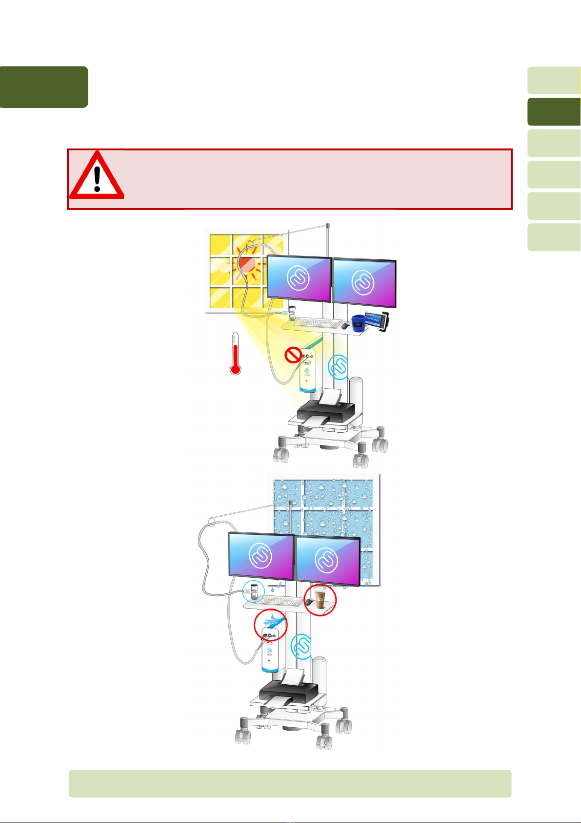
2.1 Location of the evice
Location of the Ergocar CPX
The Ergocard CPX system should not be located in wet or dusty conditions.
The cooling an on the rear panel must not be obstructed which could lead to
over-heating inside the module.

H4-EN Warnings P
AGE
14/44
2
2.2 Gas cylin ers
Depending on the options, the Ergocard device requires one or more gas cylinders. Some
recommendations need to be ollowed care ully in order to avoid any risk or the patient or
the device.
Location of the gas cylin er outsi e the trolley
Do not place a compressed gas cylinder near the system. It might all by
accident, break the system and cause injury to the patient.
Gas cylinders should be positioned at least 2 meters rom the system.
For maximum sa ty, the cylinders should be attached to the wall with a chain
to prevent them rom alling.

H4-EN Warnings P
AGE
15/44
2
Location of the gas cylin ers on the trolley
Some trollies are capable o holding the gas cylinders.
The cylinders have to be positioned vertically and attached with the straps.
The maximum number o cylinders a trolley can hold is 3. No cylinder must be
larger than 5 liters liquid.
Connection to the evice
The connection o the gas cylinders to the device is the responsibility o the
user.
The length o the tubes between each gas cylinder and the module should not
exceed 3 meters.
2.3 Displacement of the evice
Displacement of the trolley
The trolley is provided with wheels or easy movement. Be ore the trolley is
moved, the gas lines are disconnected rom the gas cylinders (i not located on
the trolley) and the power supply cable is disconnected.
The trolley should be moved care ully.
A ter the trolley is moved, activate the brakes located on the our wheels o the
trolley to prevent urther movement.
H4-EN General overview P
AGE
16/44
3
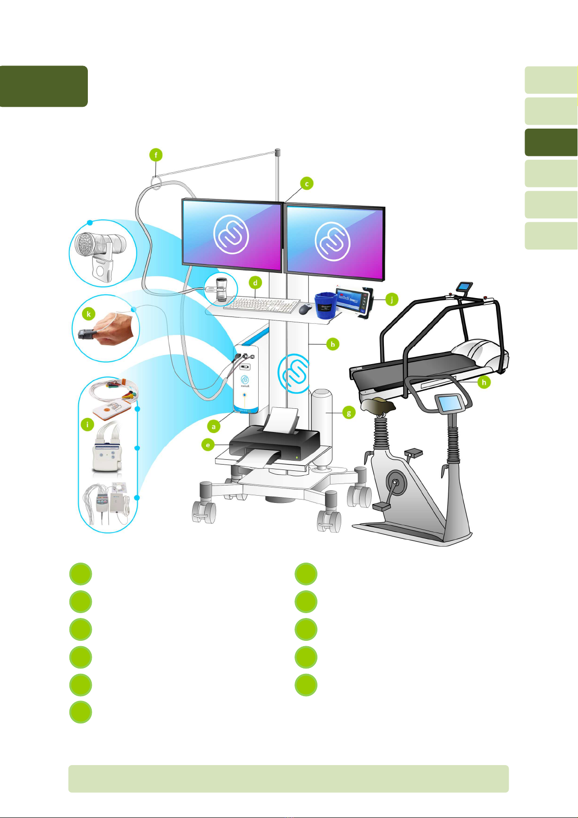
3General overview
3.1 CPET system
Ergocard CPX module
Calibration gas cylinders
Trolley or Ergocard
Ergometer (bicycle, treadmill or any
other ergometer)
Computer and dual monitors
ECG module
Keyboard and mouse
Tango non-invasive blood pressure
(NIBP) module
Printer
NONIN oximeter
Support arm or tubing
f
k
e
j
i
c
h
b
g
a
H4-EN General overview P
AGE
17/44
3
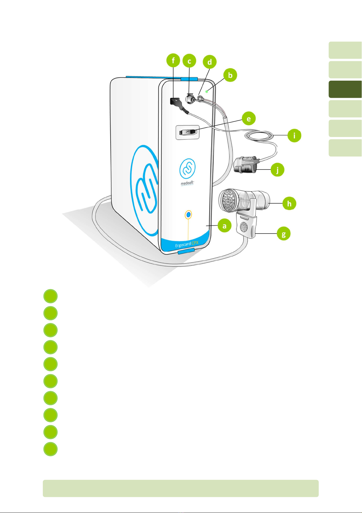
3.2 Front panel
Front panel
Power LED
Flow measurement port
Sample line port
Calibration port (connector or umbilical during calibration)
Connector or NONIN oximeter (SpO
2
)
Umbilical
Prevent low sensor
Extension or NONIN oximetry sensor
NONIN oximetry inger sensor
j
i
h
g
f
e
c
b
a

H4-EN General overview P
AGE
18/44
3
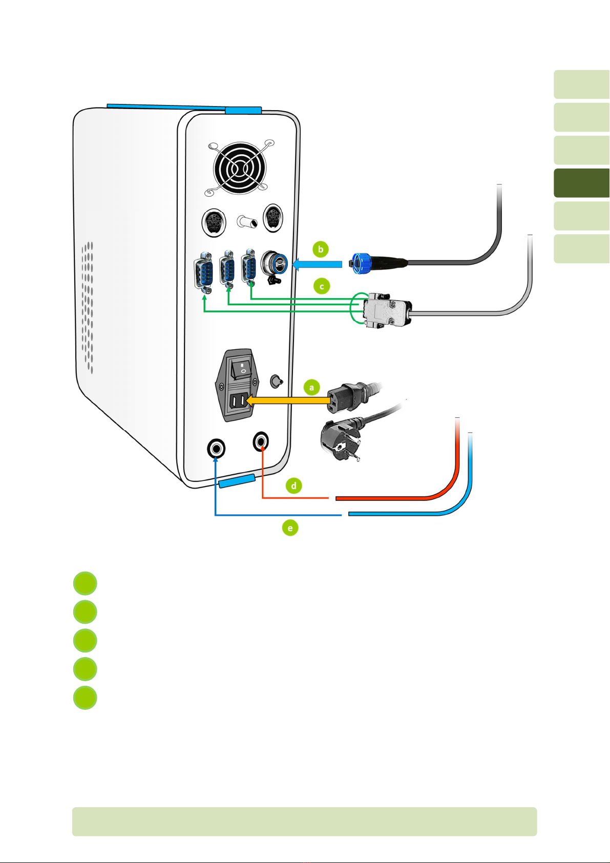
3.3 Rear panel
Rear panel
Additional serial port (COM 4)
Power switch (ON/OFF)
Gas inlet or calibration
(16% O
2
– 4% CO
2
– balance N
2
)
Power supply entry
Gas inlet or ambient calibration
(21% O
2
– balance N
2
)
USB port (connected to computer)
Cooling an
Sample low exhaust
Analog Input
Humidity sensor
Analog Output
Additional serial port (COM 3)
g
m
f
l
e
k
j
c
i
b
h
a

H4-EN Connections P
AGE
19/44
4
4Connections
4.1 Connections on front panel
To calibrate gas analyzers, insert the umbilical connector into the calibration
port. Make sure the honeycomb sticker is acing the loor (not the ceiling).
For the testing mode, connect the Prevent low sensor tube to the umbilical.
Make sure the honeycomb sticker o the umbilical connector and the
honeycomb o the Prevent is on the same side.
Connect the SpO
2
extension cable to the SpO
2
sensor.
Connect the low tube o the umbilical to the low port. Make sure you hear a
“click”.
Connect the sample tube o the umbilical to the sample port by screwing it in
care ully and completely, but not tight enough to cause damage.
5
4
3
2
1
H4-EN Connections P
AGE
20/44
4
4.2 Rear panel connections
Power supply cable
USB cable (connected to computer)
Serial cable (connected to treadmill, bicycle, …)
Gas supply tube (connected to gas tank 21% O
2
– balance N
2
)
Gas supply tube (connected to gas tank 16% O
2
– 4% CO
2
– balance N
2
)
e
c
b
a
This manual suits for next models
2
Table of contents
Other Medisoft Medical Equipment manuals


Popular Medical Equipment manuals by other brands

Shenzhen Shenke Medical Instrument Technical Development
Shenzhen Shenke Medical Instrument Technical Development SK-500II instruction manual

NormaTec
NormaTec PULSE user manual

ZOLL
ZOLL Quattro IC-4593AE/8700-0783-40 Operation manual

COINFYCARE
COINFYCARE EL02C manual

Coaguchek
Coaguchek XS System manual

Promeba
Promeba PS-155 user guide

Glacier bay
Glacier bay SP5680 Use and care guide

AirSep
AirSep Focus Portable Patient manual

Quantel Medical
Quantel Medical AXIS NANO Service manual

Otto Bock
Otto Bock Terion K2 1C11 Instructions for use

ResMed
ResMed Mirage Swift II Quick Fitting Guide

Ultra Ankle
Ultra Ankle Ultra High-5 Fitting instructions


