Medisoft Micro 6000 Instructions for use

Version 2.2
30/12/2019
H17-EN
HARDWARE USER MANUAL
Micro 6000

H17-EN Micro 6000 P
AGE
2/26
Con en
1
Foreword .................................................................................................................. 4
1.1
Foreword ..................................................................................................................... 4
1.2
Description of v il ble tests ...................................................................................... 5
1.3
List of st nd rd nd option l tests .............................................................................. 5
1.4
Intended users ............................................................................................................. 5
1.5
Environment l conditions............................................................................................ 5
2
Warnings ................................................................................................................... 6
2.1
Loc tion of the device ................................................................................................. 6
3
General overview ...................................................................................................... 7
3.1
Front p nel................................................................................................................... 7
3.2
Re r p nel .................................................................................................................... 8
3.3
H ndheld pneumot chogr ph .................................................................................... 9
4
Connec ions ............................................................................................................ 10
4.1
Connections on the front p nel ................................................................................. 10
4.2
Connections on the re r p nel .................................................................................. 11
5
Calibra ion .............................................................................................................. 12
5.1
Foreword ................................................................................................................... 12
5.2
Prep ring the equipment .......................................................................................... 12
5.3
Initi lizing the c libr tion mode ................................................................................ 13
5.4
Volume c libr tion .................................................................................................... 15
5.4.1
C libr ting the pneumot chogr ph ............................................................................................ 15
5.4.2
Checking the pneumot chogr ph c libr tion ............................................................................. 21
6
Main enance ........................................................................................................... 23
6.1
Foreword ................................................................................................................... 23
6.2
M inten nce pl nning ............................................................................................... 24
6.3
M inten nce procedures for the user ...................................................................... 25
6.3.1
Cle ning ...................................................................................................................................... 25
6.3.2
Repl cement of the pneumot chogr ph mesh .......................................................................... 25

H17-EN Micro 6000 P
AGE
3/26
Revision
Da e
Version
Modifica ions
21/02/2016
1.0
Cre tion
01/06/2018
2.0
New design
14/05/2019
2.1
Modific tion of the CE m rking
30/12/2019
2.2
Removing redund nt
inform tion’s

H17-EN Foreword P
AGE
4/26
1
1Foreword
1.1 Foreword
The Micro 6000 spirometer is desk spirometer designed for st nd rd spirometry testing for
outdoor use nd routine pr ctice in sm ll office sp ce. The h ndheld spirometer is suit ble
for spirometry in clinic l context, ph rm cology nd epidemiology studies.
The Micro 6000 is oper ted by ExpAir, softw re progr m developed by Medisoft S.A. th t
functions on Windows b sed PC systems.
The Micro 6000 is m nuf ctured, c libr ted nd pplied in conformity with l test technic l
requirements nd offici l recommend tions by ATS nd ERS. The Micro 6000 spirometer
dopts the Lilly-type pneumot chogr ph technology for flow/volume me surement. With
the spirometry option, full we ther st tion (temper ture, humidity nd b rometric sensor)
for the correct determin tion of the BTPS correction f ctor is included.
On the following p ges, you will find the instructions needed to oper te your instrument
effectively for pr ctic l uses. Ple se re d this m nu l c refully before using the device for
the first time.
The content of this document is subject to periodic upd te nd revision. Ple se note th t
some items m y be modified slightly in l test version of the softw re.

H17-EN Foreword P
AGE
5/26
1
1.2 Descrip ion of available es s
The Micro 6000 device llows the spirometry me surement.
The convention l spirometry includes:
•Slow spirometry with me surement of lung-volume subdivisions (VC, IC, ERV, Vt, RR,
VE)
•Forced expir tory m neuver (FEV1, FVC, PEF, intermedi te flows, FEF25-75…)
•M xim l volunt ry ventil tion test (MVV)
•Minute tid l ventil tion test (VE)
1.3 Lis of s andard and op ional es s
SPIROMETRY Abbrevia ion S andard/
op ional
Vit l C p city VC st nd rd
Forced Vit l C p city FVC st nd rd
M ximum volunt ry ventil tion MVV st nd rd
Minute tid l ventil tion VE st nd rd
Reversibility (pre/post) st nd rd
Ch llenge (only softw re) st nd rd
1.4 In ended users
This device is to be used by physiologists, doctors, respir tory ther pists or nurses, or under
supervision of such. D t obt ined must be interpreted nd reported by tr ined medic l
st ff only.
1.5 Environmen al condi ions
This device is for clinic l use in hospit ls, priv te doctor’s offices, medic l schools, sports
medicine f cilities or universities.
The mbient conditions must be within the specified r nge:
•Temper ture: 10 to 35°C
•Humidity: 25 to 85% (non-condensed)

H17-EN W rnings P
AGE
6/26
2
2Warnings
2.1 Loca ion of he device
Loca ion of he Micro 6000
The Micro 6000 module should not be loc ted on wet or dusty conditions.
The cooling ventil tor on the re r p nel must not be obstructed which could
le d to n overhe ting inside the module.

H17-EN Gener l overview P
AGE
7/26
3
3General overview
3.1 Fron panel
Front p nel
Power LED
H ndheld spirometer
Lilly type pneumot chogr ph
Combined tubing for h ndheld spirometer
Upstre m flow connector (+, red)
Downstre m flow connector (-, blue)
He ted wire connector
Holder for pneumot chogr ph
i
h
g
f
e
d
c
b
a
H17-EN Gener l overview P
AGE
8/26
3
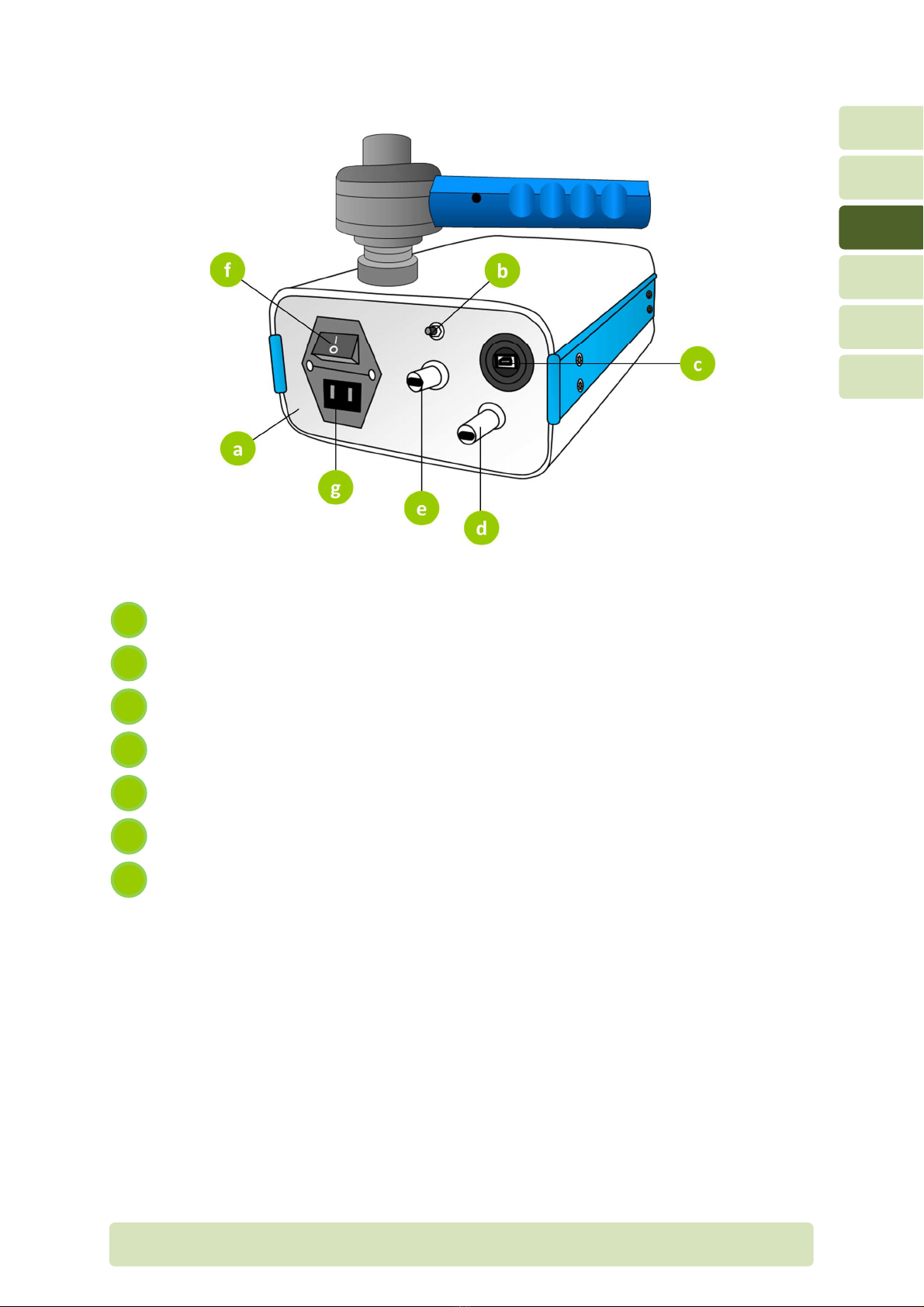
3.2 Rear panel
Re r p nel
Reset button
USB port (connected to computer)
Thermometer sensor
Humidity sensor
Power switch (ON/OFF)
Power supply entry
g
f
e
d
c
b
a

H17-EN Gener l overview P
AGE
9/26
3
3.3 Handheld pneumo achograph
Pneumot chogr ph front p rt (p tient f cing)
He ted wire nd plug
Pneumot chogr ph mesh
H ndle
Pneumot chogr ph b ck p rt (to mbient)
Antib cteri l/vir l filter
Upstre m flow line nd connector (+, red)
Downstre m flow line nd connector (-, blue)
e
d
h
c
g
b
f
a
H17-EN Connections P
AGE
10/26
4
4Connec ions
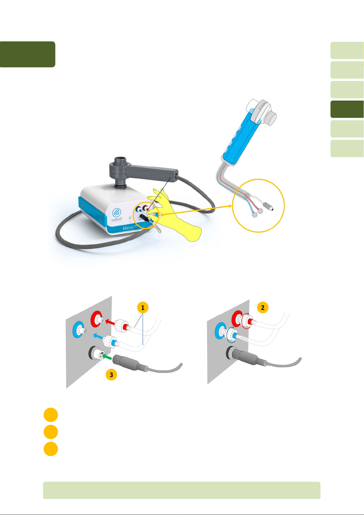
4.1 Connec ions on he fron panel
Insert the plug-in connectors to the upstre m (red)/downstre m (blue) ports
Secure the connection by clockwise rot tion of the plug-in connectors
Plug the he ted wire
3
2
1

H17-EN Connections P
AGE
11/26
4
4.2 Connec ions on he rear panel
Power supply c ble
USB c ble
b
a
H17-EN C libr tion P
AGE
12/26
5
5Calibra ion
5.1 Foreword
C libr tion of the device is essenti l to ensure correct me surement. Addition lly,
c libr tion llows lso the oper tor to detect possible problem with the module or the
module’s environment.
After c libr tion, it is possible to perform check (which is recommended by ATS-ERS
guidelines) in order to verify the qu lity of the c libr tion nd the ccur cy of the
me surement.
The t ble below summ rises the c libr tions which h ve to be performed on Micro 6000
module.
Calibra ion Min. frequency Shor descrip ion
Volume 1 x d y C libr tion of the volume/flow me surement (Lilly
pneumot chogr ph)
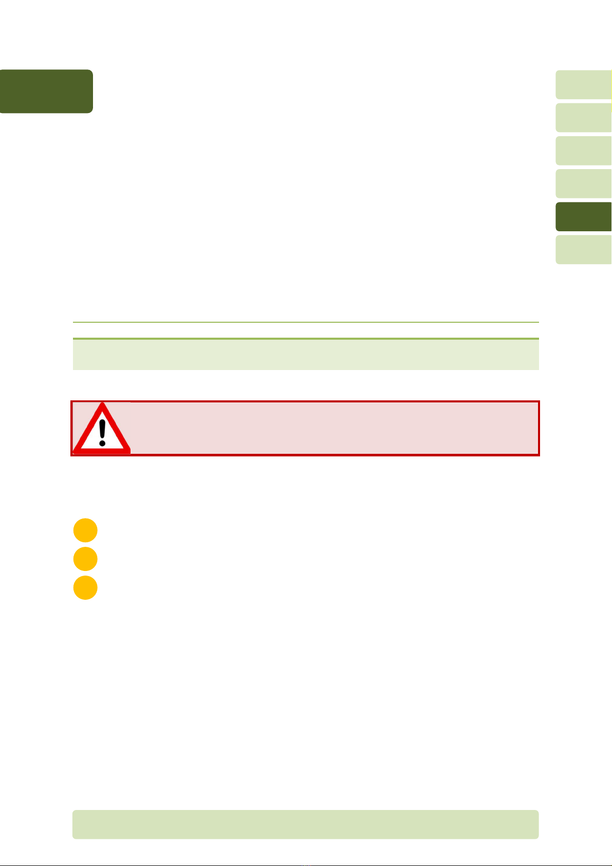
The module should be urned on a leas 20 minu es before performing he
calibra ion.
This llows the st biliz tion of the he ted pneumot chogr ph temper ture.
5.2 Preparing he equipmen
Turn on the module t le st 20 minutes before performing the c libr tion
Verify the connections of the pneumot chogr ph nd the tubing to the module
Prep re the 3 liters c libr tion syringe
3
2
1
H17-EN C libr tion P
AGE
13/26
5
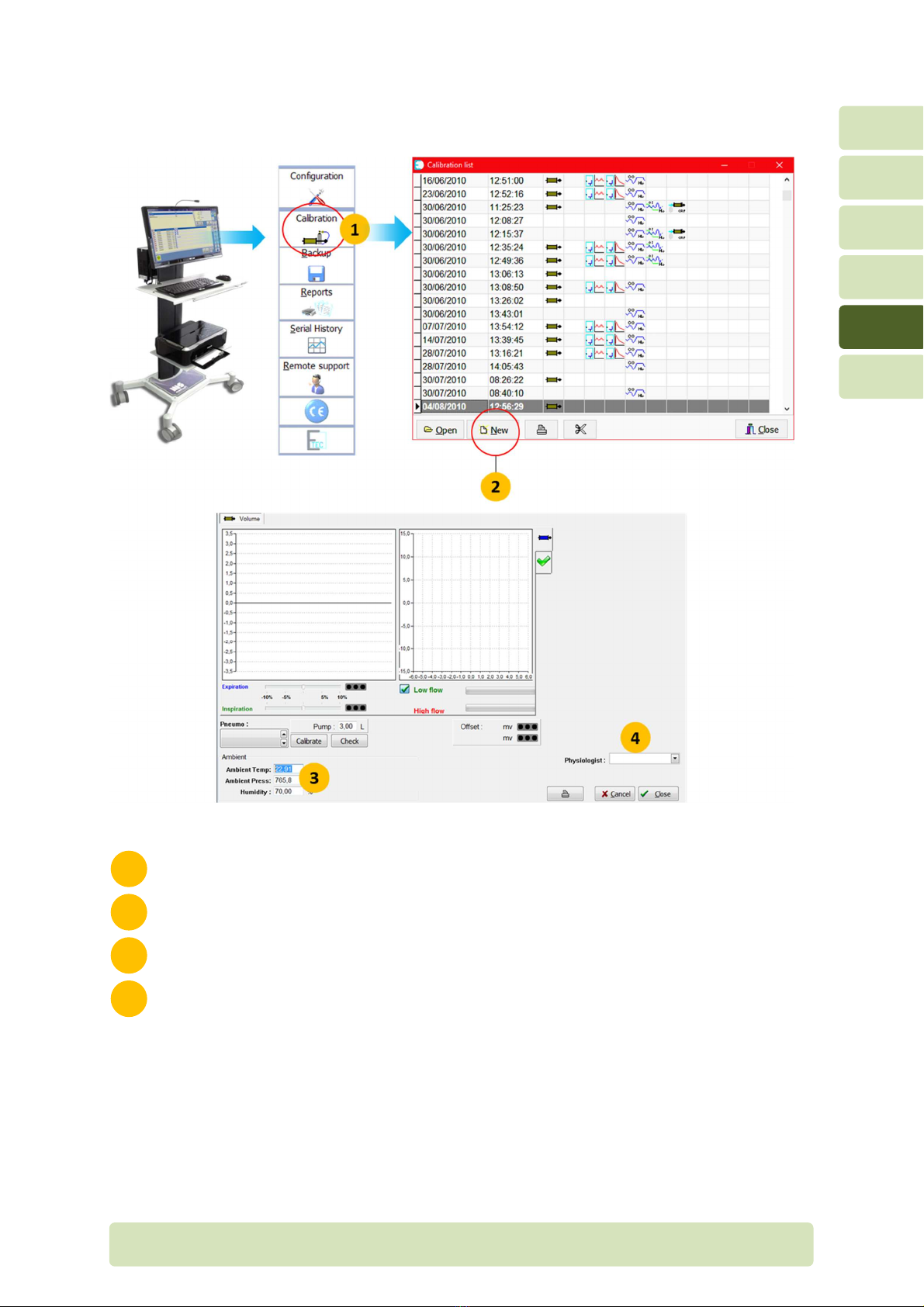
5.3 Ini ializing he calibra ion mode
On m in menu of Exp ir, select the c libr tion menu
Click on New
Check mbient conditions nd correct if necess ry
Define oper tor’s n me
4
3
2
1

H17-EN C libr tion P
AGE
14/26
5
The mbient conditions re used to c lcul te BTPS correction f ctor. It is
essenti l th t mbient conditions re me sured or encoded correctly for
ccur te volume me surement:
•Temper ture: in degrees Celcius
•Rel tive humidity: in %
•B rometric pressure: in mmHg
Impor an informa ion on barome ric pressure
The b rometric pressure used by the softw re is the ac ual b rometric
pressure, not b rometric pressure corrected t se level. Be c reful when
using n extern l we ther st tion bec use it lw ys indic tes b rometric
pressure corrected t se level, depending on the ltitude of the loc tion.
In order to obt in the re l b rometric pressure, the formul below c n be
used:
BP
BP
10.0065h
288.15
.
Where:
-BP
corr
is the b rometric pressure (in mmHg) corrected t se level, s
indic ted on ll extern l we ther st tions
-h is the ltitude (in meters)
Ex mple: we ther st tion indic tes 760 mmHg t n ltitude of 250 meters.
This will correspond to re l b rometric pressure of 738 mmHg.

H17-EN C libr tion P
AGE
15/26
5
5.4 Volume calibra ion
5.4.1 Calibra ing he pneumo achograph
Calibra ion process

H17-EN C libr tion P
AGE
16/26
5
Select the Volume t b.
Select the device (if there re sever l modules connected to the s me computer).
Define the c libr tion syringe volume (by def ult, it is set to 3 liters).
Click on Calibra e.
W it for the zero me surement (red cross).
When the green check m rk is displ yed, the device is re dy to c libr te. The flow
tr nsducer is zeroed nd sign l displ yed. Be sure the volt ge output of the flow
tr nsducer is between ± 100 mV.
Connect the 3 liters syringe to the pneumot chogr ph.
Perform sever l c libr tion syringe strokes (being sure to include the entire volume,
end to end of the syringe) t medium const nt flow r te.
After 5-6 full strokes of the syringe, the c libr tion results ppe r. Click on Close to
ccept the new c libr tion d t or Cancel to perform new c libr tion.
An lyse the results of the c libr tion.
10
9
8
7
6
5
4
3
2
1

H17-EN C libr tion P
AGE
17/26
5
Analysis of he volume calibra ion resul s
An lysis of the c libr tion results is essenti l to ensure n ccur te volume me surement by
the system.
Flow-volume loop
During the c libr tion process, the flow-volume loops re displ yed, the volume is on the
horizont l xis nd the flow is on the vertic l xis. There should be no drift on the horizont l
xis s shown below. A m jor drift is the sign the c libr tion is not ccept ble nd
verific tion of the system is required.
Tr ffic lights signific tion
During the c libr tion process, two c libr tion f ctors re c lcul ted, one for inh led
volume, one for exh led volume. The tr ffic lights indic te the devi tion of the c libr tion
f ctors rela ive o he fac ory (reference) calibra ion.
Devia ion less han 5%. The c libr tion is good nd the system c n be used.
Devia ion be ween 5 and 10%. The c libr tion is ccept ble but verific tion
of the system is recommended.
Devia ion grea er han 10%. The c libr tion is not ccept ble.
A verific tion of the system is required.

H17-EN C libr tion P
AGE
18/26
5
Verific tion of the system
If one or two tr ffic lights re yellow or red, the oper tor h s to perform verific tion of the
system described below.
1. Verify the connection of the tubing to the module (red nd blue connectors).
2. Verify the mesh of the pneumot chogr ph. It should be cle n, free from dust nd gre se.
The screen of the mesh should be fl t, without distortion. If necess ry, cle n it c refully
or repl ce it.
Remove the pneumot chogr ph from the h ndle.
T ke the pneumot chogr ph from the lower p rt nd turn counter clock wise the
upper p rt in order to dis ssemble the pneumot chogr ph.
Remove c refully the mesh without putting finger on the screen.
The pneumo achograph mesh should be manipula ed carefully.
Any damage on he mesh could affec he flow/volume measuremen .
3
2
1

H17-EN C libr tion P
AGE
19/26
5
3. Verify the pneumot chogr ph is ssembled correctly nd fitted securely to the h ndle.
4. Verify the correct syringe volume (indic ted on l bel on the syringe) is the s me
volume entered into the softw re.
5. Verify the c libr tion syringe is not d m ged nd h s no le k.
Calibration syringes should ideally be checked and calibrated annually by a calibration
laboratory.
Put the syringe on t ble nd position the piston t the middle.
Close the syringe with the p lm of your h nd.
Press slowly to the piston.
If the syringe h s no le k, the piston should move only few millimetres
due to the compression of the ir inside the syringe.
If the syringe h s le k, the piston moves under the ction of const nt
pressure on it.
Repe t the m neuver t different position of the piston.
4
3
2
1

H17-EN C libr tion P
AGE
20/26
5
After the verific tion of the system
Perform second c libr tion of the pneumot chogr ph nd check the results.
Devia ion less han 5%. C libr tion is now good nd the system c n be used.
Devia ion be ween 5 and 10%. The c libr tion is ccept ble nd the system
c n be used. The devi tion could be sign th t device m inten nce is
necess ry. Ple se cont ct your Medisoft represent tive.
Devia ion grea er han 10%. The c libr tion is not ccept ble. A verific tion of
the system by field service technici n is required. Ple se cont ct your
Medisoft represent tive.
Table of contents
Other Medisoft Medical Equipment manuals


Popular Medical Equipment manuals by other brands


Getinge
Getinge Arjohuntleigh Maxi Sky 600 ECS Instructions for use

MIR
MIR Minispir New quick start guide

Halyard
Halyard On-q QUIKBLOC Instructions for use

Hico Medical Systems
Hico Medical Systems HICO-VARIOTHERM 550 Instructions for use

ANCEL
ANCEL AD310 user manual

Monitex
Monitex CAPSULE MIXER CM-II Instructions for use